MICROGRID INVERTER OPERATION
IN THREE PHASE GRID-CONNECTED
AND DISCONNECTED MODES
ASWATHY JEEVAN
Electronics & Communication Department, MG University, Ilahia College of Engineering & Technology, Muvattupuzha, Kerala, India
mail4aswathyjeevan@gmail.com
B MOHAMMED IMRAN
As Professor, College of Computer Science and Information Technology, University of Dammam, Dammam, Kingdom of Saudi Arabia
professor.imran@gmail.com http://mohammed.imran.tripod.com/
Abstract:
A Microgrid consists of interconnected distributed generators, loads and intermediate storage units. Microgrid inverter is used for the complex control of Microgrid. This paper introduces two modes of operation for Microgrid inverter. They are Grid Connected and Grid-Disconnected modes of operation. When a Microgrid is grid-connected, it behaves as a controllable load or source. During this mode of operation, the primary function of the Microgrid is to satisfy its entire load requirement. When in Grid-Connected operation, it uses current tracking by adjusting the output current to the grid to achieve energy transmission. The Microgrid should disconnect when an abnormal condition occurs in the grid. It uses voltage close loop control, by adjusting the output voltage to ensure stable load voltage when it is disconnected. Microgrid inverter switches smoothly between two modes, when grid fails or recovers. The Microgrid inverter used in this is a three phase inverter. This is mainly for high power applications. This increases feasibility, power and effectiveness of control strategy
Keywords: Microgrid Inverter, Grid-Connected mode, Grid-Disconnected mode, Hysteresis Current, Photovoltaic.
1. Introduction
Recently, the distributed generation (DG) units are increasingly used. DGs are used mainly because of their eco-nomical and environmental benefits compared to the use of large power plants. DGs can provide high power reliability and security and lower-cost electricity than can traditional power generators. Day-by-day, the advantage of using dis-tributed generators in distribution networks increases and produces larger benefits to the consumers. First the DGs in-tegrate eco-friendly renewable energy resources such as so-lar cells, wind turbines and fuel cells to distribution net-works [1-3]. Second, the DGs can be installed in close proximity to end-use consumers due to the size and clean energy technology.
The introduction of the microgrid opens new opportunities for the coordinated operation of the distributed energy resources (DER). The Consortium for Electric Reliability Technology Solutions (CERTS) presents a microgrid as a system providing both power and heat [4]. A microgrid is an electrical system that includes multiple loads and distributed energy resources that can be operated in parallel with the broader utility grid or as an electrical island. It is connected to the grid at the point of common coupling or PCC. Microgrids can enhance local reliability, support local voltage, reduce feeder losses, increase efficiency through CHP and provide uninterruptible power supply (UPS) functions.
It is common the use of renewable sources and other small scale in distributed generators systems equipped with Voltage Source Inverter (VSI) or Current Sources Inverters (CSI). Parallel redundant VSI are used in Uninterruptible Power Supplies (UPS) applications to increase the reliability of the electrical network. Anti-islanding techniques have been used to disconnect distributed generators in front of grid faults, as in [5] – [6].
2. Microgrid Structure
The MicroGrid structure is a collection of loads and micro sources operating as a single system providing both power and heat. The majority of the micro sources are power electronic that provides flexibility and insures controlled opera-tion as a single aggregated system. Key issues that associated with MicroGrid structure include the interface, control and protection requirements for each micro source as well as MicroGrid voltage control, power flow control, load sharing during islanding, protection, stability, and over all operation. MicroGrid is able to operate connected to the grid as well as smooth transition to and from the island mode. This is one of the most important function of Microgrid.
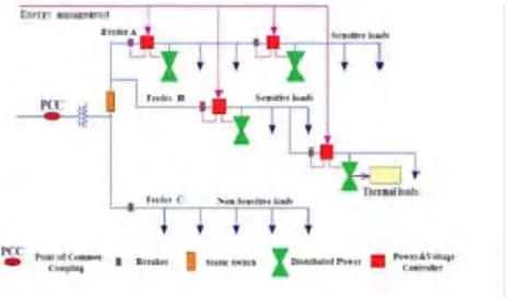
Fig.1 Microgrid basic structure (U.S CERTs)
The Figure 1 illustrates the basic MicroGrid architecture. The electrical system consists of three feeders – A, B, and C – and a collection of loads. The micro sources are either micro-turbines or fuel cells interfaced to the system through power electronics. The Point of Common Coupling (PCC) is on the primary side of the transformer and defines the separation between the grid and the MicroGrid. The sources on Feeder A & B allow full exploration of situations where the micro sources are placed away from the common feeder bus. It reduce line losses, support voltage and/or use its waste heat. Each feeder has several circuit breakers and power and voltage flow controllers. The traditional loads are on Feeder C. They are left to ride through the disturbance. This eliminates nuisance trips of the traditional load when the MicroGrid islands to protect critical loads. There are several factors driving the gradual development and integration of microgrids. They are as follows:
(1) Reduction in environment pollution: by using low or zero emission microsources within the microgrid networks.
(2) Utility grid support: Microgrids usually operate in parallel with the utility grid to feed a certain load. This prevents the grid being overloaded during peak load periods, which may consequently result in blackouts. (3) Reduction in the transmission losses (economic benefit) [2]: Power delivered to areas where microgrids are
installed are lower and losses on the lines are lower too. This decreases the consumption of fossil fuel by the conventional generators.
(4) System reliability: microgrids can operate in both grid-connected and autonomous mode. This ensures that the uninterrupted and high quality power is delivered to the loads, particularly critical loads.
(5) Thermal energy savings when Combined Heat and Power (CHP). There are no technical difficulties associated with the location of a microsource in a microgrid. Thus, microsources can be placed near thermal and electrical loads to maximize energy efficiency and utilize the otherwise wasted heat.
The MicroGrid assumes three critical functions that are unique to this architecture:
Microsource Controller. Micro source consists of Power and Voltage Controller. It provides fast response to disturbances and load changes without relying on communications.
Energy Manager. Provides operational control through the dispatch of power and voltage set points to each Micro source Controller. The time response of this function is measured in minutes.
Protection. Protection of a MicroGrid in which the sources are interfaced using power electronics requires unique solutions to provide the required functionality.
The finer particles are carried through the outlet of the coal mill to the burner of the boiler.
The connected loads may be critical or non-critical. Critical loads require reliable source of energy and demand stringent power quality. These loads usually own the micro sources because they require a continuous supply of energy. Non-critical loads may be shed during emergency situations and when required as set by the microgrid operating policies.
The intermediate energy storage device is an inverter interfaced battery bank, super capacitors or flywheel. The storage device in the microgrid is analogous to the spinning reserve of large generators in the conventional grid. They ensure the balance between energy generation and consumption especially during abrupt changes in load or generation.
Fig.2 An Example Microgrid
3. System Modelling
The main components of modelling of microgrid consists of components such as microsource, microgrid loads, utility grid, point of common coupling and phase locked loop.
3.1. Microsource
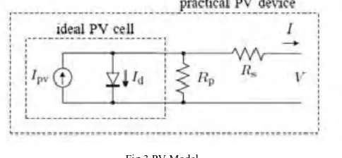
Microsource units in a microgrid can be either conventional generators, such as synchronous and induction generators, or renewable energy units. The modelling of microsource will cover only PV systems and three phase inverters. The two important parameters of PV system is ambient temperature and irradiance. A basic solar cell can be symbolized by an electrical equivalent circuit with one diode model. The cell circuit is shown in figure.
Fig 3 PV Model
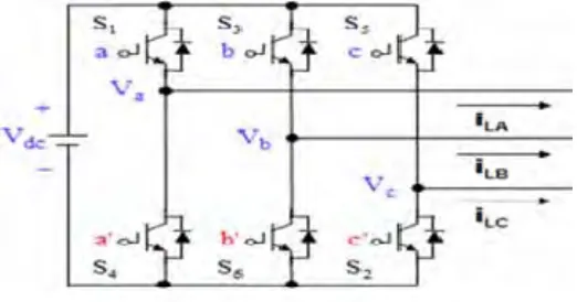
Fig4: Three phase voltage source inverter
3.2. Microgrid Load
Microgrid Load models consist of simple 3 phase series RL branches with constant impedances as shown in the figure 5. Loads in grid side will be disconnected by a controllable switch when the microgrid is islanded.
Fig 5.Load model
3.3.Utility Grid
During the simulation of the microgrid in grid-connected mode, the grid side can be modelled as a 3 phase power source that is connected through distribution lines to a step down transformer.
3.4.Point of Coupling
The point of common coupling can be modelled as a controllable 3 phase circuit breaker. This is shown in figure 6. This breaker is a time-based controllable switch that opens and closes its contacts according to defined operation times. The reason for choosing a time-based breaker rather than a controllable static switch, is because Simulink does not have the tools needed to simulate the conditions.
Fig 6 Time based circuit breaker
4. Control Strategies for Microgrid Operation
Microgrid inverter operates in two modes. They are Grid-connected and Grid- disconnected modes. One of the most important characteristics of microgrid inverter is being able to run by breaking away from the main grid. But traditional Grid-connected inverter doesn’t run when the grid fails.
4.1.Grid-connected mode
When the microgrid is operating in parallel with the utility grid, the frequency within the microgrid, the voltage amplitude at the connection points of the inverters to the feeder, and the power supplied by microsources need to be properly controlled and maintained. The voltage amplitude can be simply adjusted internally by using the PWM technique [10]. The frequency of the microgrid, on the other hand, can be maintained by using a phase looked loop (PLL) technique that synchronizes the microgrid with the utility grid. This is done by adjusting the voltage phase angle of each inverter phase to the corresponding phase in the grid. Therefore, the voltage and the frequency of the inverter are indirectly controlled by the grid.
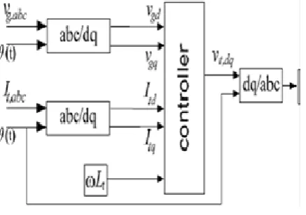
In this type of Constant Current Control, the microsource unit is forced to supply a constant current output. The control block diagram for this type is shown in Figure 5[11]
Figure 5: Constant current control block diagram
The constant current control method is used to measure the load voltage Vabc and the inverter current Iabc and transfers them to a DQ frame. The PLL is used to estimate the phase angle at the microsource connection point. The current quantities Id and Iq are then compared with reference DC quantities to obtain error signals. The error signals are then applied to proportional-integral controllers to correct the errors.
4.2.Grid-Disconnected Mode
As the voltage drop, fault, power outage maintenance and other causes interruption of external power connection, microgrid inverter can smoothly transform from Grid-connected operation to Grid-disconnected operation. Microgrid inverter provides power to important loads. After faults remove, the static switch closes; microgrid inverter can steadily switch from Grid-disconnected operation to Grid-connected operation.
5. Simulation Results
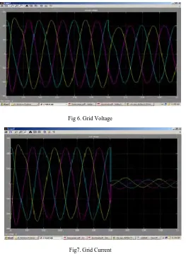
Microgrid inverter connects to the grid, at the 0.06s moment it disconnects to the grid, the corresponding results are shown below. The grid has no effect to the operation of microgrid inverter in the disconnected-grid mode. Before the 0.06s, microgrid inverter connects to the grid, microgrid inverter and the grid provide energy to the loads together. After disconnected-grid, the grid does not provide energy to the load; microgrid inverter provides power to sensitive loads, which ensures uninterrupted power supply sensitive loads.
Fig 6. Grid Voltage
Fig7. Grid Current
Fig8. Inverter Voltage
Fig 9 Inverter Current
6 Conclusion
This paper summarizes the traditional independent three phase inverter and Grid-connected inverter control strategy, combining the distributed power and microgrid inverter characteristics, a suitable for microgrid inverter control strategy is put forward. Switching between Grid- connected mode and Grid disconnected mode for microgrid inverter has been studied .On the Grid-disconnected operation mi-crogrid inverter supplies the important loads that ensures load voltage and frequency stability. Microgrid inverter can smoothly switch between Grid-connected operation and Grid-disconnected operation, switching operati.on of the system has good performance. The system controller design is simple, practical and efficient.
References
[1] T.Green and N.Pogaku, A model citizen approach to integrating inverter-based distribution generation "World Renewable Energy Congress (WREC)", 2005,pp.1101-1108.
[2] E Barklund, N. Pogaku, M. Prodanovic, C. Hernandez Aramburo, and T.C.Green, "Energy management in autonomous microgrid using stability-Constrained droop control of inverters", IEEE Trans on Power Electron., Sept.2008 ,vol.23, no.5.pp 2346-2352 [3] R. H. Lasseter,A.Akhil, C.Marnay, J. Stephens, J. Dagle, R. Guttromson, A.Meliopoulous, R.Yinger, and J. Eto, "The CERTS
microgrid concept, white paper on integration of distributed energy resources". California Energy Commission, Office of power technologies- U.S. Department of Energy, Apr.2002
[4] C. Marnay and G. Venkataramanan," Microgrids in the evolving electricity generation and delivery infrastructure", in Proc. IEEE PES General Meeting, Montreal, Canada, 2006 June 18-22
[5] Z. Ye,A. Kolwalkar,Y. Zhang, P. Du, and R. Walling, "Evaluation of anti-islanding schemes based non detection zone concept", , IEEE Transactions on Power Electronics, vol.19, pp. 1171- 1176, 2004
[6] M. Liserre, A, Pigazo, A. Dell Aquila, and V.M Moreno, "An Anti-Islanding Method for Single Phase Inverters Based on a Grid Voltage Sensorless Control", IEEE Transactions on Industrial Electronics, 2006 , vol.53, pp.1418-1426
[7] J.M. Guerrero, N. Berbel, J. L. Sosa, and L.G. de Vicunna," Control of Line-Interactive UPS Connected in Parallel Forming a Microgrid", presented at IEEE International Symposium on industrial Electronics, 2007. ISIE 2007.
[8] Robert H.Lasseter and Paola Piagi, "Control and Design of Microgrid Components", 2006, University of Wisconson-Madison. [9] Rym Marouani and Abdelkader Mami, "Voltage Oriented Control Applied to a Grid Connected Photovoltaic System with Maximum
Power Point Tracking Technique". http://www.scipub.org/fulltext/ajas/ajas781168-1173.pdf, accessed on 13/08/2010. [10] Muhammad H.Rashid," Circuits, Devices and Applications on Power Electronics", 2004, 3rd Alexandria, VA: Prentice Hall
[11] M.Popov, H. Karimi, H. Nikkhajoei and V. Terzija," Dynamic Model and Control of a Microgrid with Passive Loads". http://www.ipst.org/techpapers/2009/papers/20.pdf. Accessed on 22/08/2010
[12] H. Al-Nasseri, M. Redfern, "A new voltage based relay scheme to protect microgrids dominated by Embedded Generation using solid state converters" Proceedings of 19th international conference on Electricity Distribution
