HYBRID METHOD FOR ANALYSE
DISCONTINUITIES IN SHIELDED
MICROSTRIP
MOHAMMED EL AMINE EL GOUZIElectronic and instrumentation Laboratory, Department of Physics, Faculty of science – B.P: 2121 TETOUAN / Morocco
[email protected] M. BOUSSOUIS
Electronic and instrumentation Laboratory, Department of Physics, Faculty of science – B.P: 2121 TETOUAN / Morocco
[email protected] Abstract:
A rigorous full-wave analysis is employed to analyze discontinuity in shielded Microstrip (open end, uniform bend). An accurate and efficient method of moments solution combined with the source method(SM) formulation is proposed in order to achieve a full-wave characterization of the analyzed structures. A wavelet matrix transform (WMT), operated by wavelet-like transform (WLT) allows a significant reduction of the central processing unit time and the memory storage.
1. INTRODUCTION
Analysis of discontinuities in transmission lines plays essential role in modeling complex microwave and millimeter wavelength circuits. Various microstrip discontinuities have been analyzed in recent years using a wide range of techniques such as mode-matching assuming a magnetic wall approximations in computing microstrip line modes [4], Frequency Domain Techniques using Electric Field Integral Equations based on spatial-domain analysis methods [12-5] or spectral-domain approaches [10,8]. More recently other numerical techniques such as Time-Domain Transmission Line Matrix (TLM) technique [9,20], Finite Difference Time Time-Domain (FDTD) approach [10-5] have also been applied to treat discontinuity problems. A mode matching for step discontinuities in microstrip lines have been presented in [23].
The source method developed by some authors [15,3], is a rigorous approach which permits to reduce the CPU-time requirements. The boundary conditions are verified by solving a system of linear equations. So, the iterations needed by the Eigen value methods are avoided. The source represents the feeding of the access line by means of a coaxial cable. The source is either punctual [16, 17] or defined on a small sub region of the circuit [15, 11, 3]. This last case is used in this paper: an arbitrary function describes the source current density. The solution of the system will give a model of the current density on all the circuit with the help of trial functions appropriately chosen. The Galerkin's method is used. The numerical value of the input impedance, or the impedance matrix seen by the sources, is easy to compute with a variation formula [16, 3, 7]. However, the impedance matrix generated by MOM is always a dense matrix, which often becomes computationally expensive and memory consuming, especially when the electrical size of the object becomes large [6]. To overcome this difficulty, various algorithms have been developed during the past decades, such as the fast multiple method [18–14], the adaptive integral equation method [1], the conjugate gradient-fast Fourier transform algorithm [19, 27], and the wavelet transform method [22–25].
and then the wavelet transform (WT) is applied to the impedance matrix to obtain a sparse matrix equation in wavelet domain [13–21].
The computational cost is substantially reduced by implementing the wavelet matrix transform (WMT) and a great amount of research papers about WT have been published by EM researchers.
In the mentioned work, a combination of Wavelet-Like Transforms and Source Method is used to reduce the CPU-time requirements to analysis of microstrip discontinuities.
2. Theory
2.1. Source method
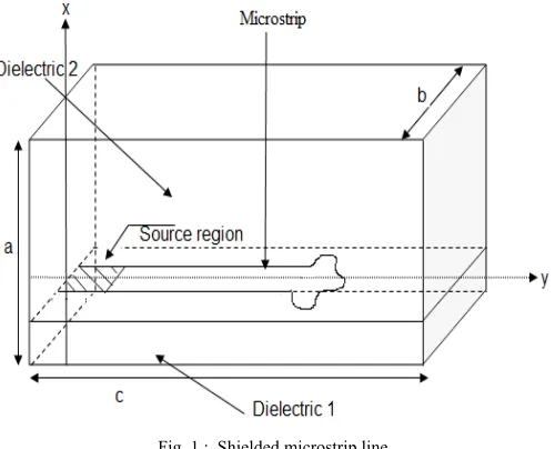
To explain clearly the development of the theoretical formulation, we use to a large extent the formalism presented in [1]. The structure is a shielded metallic box (Fig. 1). The planar circuit is supposed lossless. A voltage source placed on the circuit plane is used and the characterization is made by modeling the current density with the help of appropriate trial functions.
Fig. 1 : Shielded microstrip line
A relation between the electric tangential field ET on the plane x = h and the total current density J is defined.
E
T
Z
ˆ
.
J
(1)Z is a projection operator on the TE mn
f
and TM mnf
modes of the empty waveguide. An inner product is defined by:
a
b
a
*.
b
.
dS
(2)Where
a
*is the conjugate vector ofa
Z
ˆ
is expressed as follows :
TM mn n
m
TM mn TM mn TE
mn n
m
TE mn TE
mn f g f Z f g f
Z g
Z
, ,
. ˆ
(3)
The mode impedances TE mn
Z and ZmnTM are defined by using a transverse resonance method [14] :
Z jk0[ mn1 cot anh ( mn1 (a d1)) mn2 cot anh ( mn2 d1)
TE
mn (4)
) ( cot ))
( ( cot 1 [ 1
1 2 2
1 1
1 0
d anh d
a anh
k j
Z mn
mn r mn
mn TM
mn
Where ; 0 0 2 0 2 2 2 2 2 0 2 2 2 1 2 ) ( ) ( ) ( ) ( ) ( ) ( c f k k c n b m k c n b m r mn mn
(Co is the light speed in vacuum).
The solution of the problem consists in satisfying the following boundary conditions:
0 0 J E T
(6)
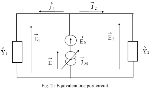
The planar dipole can be modeled with equivalent diagram as shown in Fig. 2:
Fig. 2 : Equivalent one port circuit.
The equation (6b) will be automatically satisfied by choosing the total current density on the circuit. The equations (1) and (6a) gives us the following relation:
ˆ
.
0
J
Z
On (M) (7)By using a source type formulation, the metallic strip is subdivided into two sub regions named (M) and (S) (Fig. 1). They represent the definition domains of the current density functions. An arbitrary excitation J0 is defined on the
(S) sub region, on the plane of the strip. Thecurrent density on the (M) sub region is expressed in term of a trial functions basis { gi, i = 1 to N}. The equation (7) becomes:
0 1
.
ˆ
.
ˆ
x
g
Z
J
Z
N i i i
On (M)
(8)The unknowns xi (i = 1 to N) have to be computed by solving the equation (8). The (S) and (M) sub regions must be
inevitably separated. So this theory will be used with the following condition: The trial functions must not be defined on the (S) sub region.
The excitation function cannot be defined on the (M) sub region.
A source-type method permits a really fast computation of the problem by solving a deterministic system. This system is obtained by applying Galerkin's method to the equation (8). The kth line is:
1 0
. ˆ .
ˆ x g g Z J
Z g k N i i i k
(9)
Then the system of matrix equation (3) can be expressed as:
A
X
B
(10)
The expression of Z given by (3) allows us to write the equation (9) under the following form (Equation 11): (a) On (M)
n m TM mn TM mn TM mn k n m TE mn TE mn TE mn k n m N i i i TM mn TM mn TM mn k n m N i i i TE mn TE mn TE mn k J f Z f g J f Z f g g x f Z f g g x f Z f g , 0 , 0 , 1 , 1 (11)The inner products are made on the (S) and (M) sub regions which are the definition domains of the trial and source functions. The excitation term must nevertheless be chosen with the greatest precaution since it must disrupt the least possible the continuity of the current at the interface between (S) and (M). Then, the form of the source function and the size of the (S) subregion have an influence on the final computed result. When the current density is known on any point of the circuit, a one-port network can be characterized by its input impedance Zin, seen by the
source. A variational expression is associated to the equation (8) [7]:
0 0*
0
0 ˆ( )
I I g x J Z J Z i i i in
(12)
Where
I
0 is the source current.2.2. Choice of sources and trial functions
The modeling of a planar circuit consists of determining its behavior by calculation and programming. Efficiency and accuracy of the computation can be improved by the choice of appropriate sources and trial functions.
In this paper, a constant source has been chosen, composed of only one component in the z direction. This source function permits a good numerical convergence. Trial functions {gi} are roof top functions.
2.3. Wavelet-like transform
The principal advantage of using wavelets in the MoM is the sparsely of the calculated impedance matrices. The system of matrix equation in moment method can be expressed as:
A
X
b
(13)
By a WMT method, Equation (13) is transformed as
A
w
X
w
b
w (14)Where
A
WAW
X
W
X
b
wWb
t w
t
w
,
)
(
,
1(15)
Transformation t
WAW
is a 2D wavelet transform which act on rows and columns of A respectively and is called a wavelet-like transform of A [9, 10].The unknown X is found by solving (14).
X
W
WAW
Wb
t t
(
)
1
(16)
n nG
H
h
h
h
h
h
h
h
h
h
h
h
h
h
h
h
h
h
h
h
h
h
h
h
h
h
h
h
h
h
h
h
h
h
h
h
h
h
h
h
h
h
h
h
h
h
h
h
h
P
8 8 1 0 5 4 3 2 3 2 1 0 5 4 5 4 3 2 1 0 5 4 3 2 1 0 4 5 0 1 2 3 2 3 4 5 0 1 0 1 2 3 4 5 0 1 2 3 4 50
0
0
0
0
0
0
0
0
0
0
0
0
0
0
0
(17)
At each level of decomposition, matrix Pn must constructed such that to perform decomposition only on lowpass
coefficients ( Hn ) of the previous stage. Before applying the wavelet transform a rescaling and normalizing
according to the following equation could be useful.
)
,
(
)
,
(
)
,
(
)
,
(
j
j
A
i
i
A
j
i
A
j
i
A
, i,j =1 :N (18)Matrix Aw is now converted to a sparse matrix Aδ by thresholding with parameter δ. To investigate errors produced
after applying a threshold, we define two kinds of error:
Reconstruction error: The reconstruction error is the difference between the actual elements of the matrix and the one reconstructed from the thresholded wavelet coefficients [10]. Reconstruction means to apply inverse wavelet transform to the thresholded matrix.
Relative error of any desired solutions before and after thresholding moment matrix.
3. Numerical results
In this section, we present two examples to demonstrate the efficiency and accuracy of the present technique.
3.1. Application to uniform microstrip
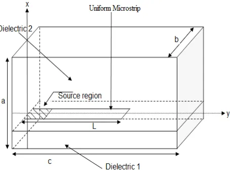
As the first example, we have applied both techniques to a uniform Microstrip whose geometry is shown in Fig. 3 in equal conditions (i.e. dimensions, frequency) to compare our method with conventional MoM . We have developed a computer program in MATLAB to implement the procedures described in previous sections.
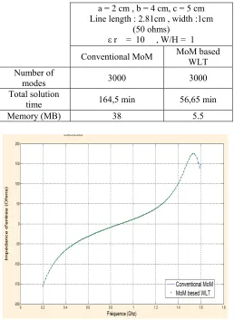
The computational resource requirements of the conventional MoM and our method are listed in Tables I , It is observed that MoM takes about 164,5 min to compute the solution on a Pentium IV PC while our method takes only 56,65 min.
Table I: RESOURCE requirement of both techniques
a = 2 cm , b = 4 cm, c = 5 cm Line length : 2.81cm , width :1cm
(50 ohms)
ε r = 10 , W/H = 1 Conventional MoM MoM based WLT Number of
modes 3000 3000
Total solution
time 164,5 min 56,65 min
Memory (MB) 38 5.5
Fig 4: Stub input impedance (a = 2 cm, b = 4 cm, c = 5 cm, H = 1 cm, ε r , = 10).
3.2. Application to the right angle bend
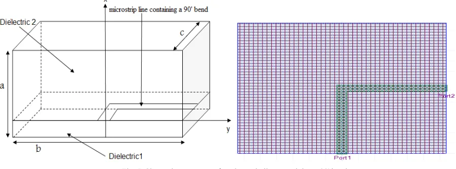
The next example is Microstrip line containing a 90’ bend whose geometry is shown in Fig. 5 which is fabricated on a substrate with relative permittivity 9.8 and thickness H = 0.635 mm.
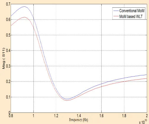
To validate our results, Magnitude of S11 of this structure are depicted and compared with that of conventional MoM
Fig. 5: Shows the geometry of a microstrip line containing a 90' bend.
After applying wavelet-like transform the ratio of biggest element to smallest element is increased about 106 times, this indicates that the matrix is sparse.
Table 2 : Sparsity and Errors Related To Different Values Of threshold
Threshold
δ Sparsity Percent Error of R(%) Solve Reconstruction Error (%) 1.00E-06 8.9367 4.56 E-06 0.00010543 1.00E-05 25.492 0.000134657 0.003418 1.00E-04 45.5 0.0056432 0.02631
1.00E-03 52.45 0.452 0.2614
1.00E-02 67.362 0.74321 2.6738
Choosing the threshold parameter δ = 0.0001, leaves reconstruction and solve errors quite small about a few tenth of percent. We must pay more attention to choose δ at frequencies around the resonance.
Table III: Resource requirement of both techniques for
a = 3.81cm , b = 12.7 cm, c = 12.7 cm
width : 0.635 mm (50 ohms)
ε r = 9.8 , H = 0.635 mm Conventional MoM MoM based WLT Number of
modes 3000 3000
Total solution
time 66,7 hours 12,4 hours
Memory (MB) 635.45 24.4
Fig. 6: MAG (S11) of right-angle bend at box resonances a = b = 1.9 mm, c = 0.2 mm, H = 0.1 mm, W / H , = 1).
4. Conclusion
In this paper, a full wave analysis of microstrip discontinuities by moment method based wavelet-like transform was presented. We used wavelet-like transform to sparsify the moment matrix considering the errors generated in the process. We illustrated that our method has much potential in the area of the analysis and CAD of complex MMIC structures and is capable of being enhanced in a number of ways to improve computational efficiency and accuracy. Numerical results were presented for our proposed method, based on developed MATLAB codes, and good agreement with conventional MoM.
5. Reference :
[1] BLESZYNSKI E, BLESZYNSKI M, JAROSZEWICZ T. " AIM: adaptive integral method for solving large-scale electromagnetic scattering and radiation problems". Radio Science 1996; 31:1225–1251.
[2]. BARMADA S, RAUGI M. "Analysis of scattering problems by MOM with intervallic wavelets and operators". Applied Computational Electromagnetics Society Journal 2003; 18:62–67.
[3] BAUORAND H. "Tridimensional methods in monolithic microwave integrated circuits". SMBO Brazilian Symposium NATAL (27-29 July 1988), pp. 183-192.
[4] Chu, T. S., T. Itoh, and Y. C. Shih, "Comparative study of mode matching formulations for microstrip discontinuity problems," IEEE Trans. Microwave Theory Tech., Vol. 33, 1018-1023, Oct. 1985.
[5] Feix, N., M. Lalende, and B. Jecho, "Harmonical characterization of a microstrip bend via the finite-difference time-domain method," IEEE Trans. Microwave Theory Tech., Vol. 40, 958-961, May 1992.
[6] GOLIK WL. "Wavelet packets for fast solution of electromagnetic integral equations". IEEE Transactions on Antennas and Propagation 1998; 46:618–624.
[7] HARRINOTON R. F. "Time-harmonic electromagnetic fields". Mc Graw-Hill Book Company (1961).
[8] Hill, A., and V. K. Tripathi, "An efficient algorithm for the three- dimensional analysis of passive microstrip components and disconti- nuities for microwave and millimeter-wave integrated circuits," IEEE Trans. Microwave Theory Tech., Vol. 39, 83-91, Jan. 1991.
[9] Hoefer, W. J. R., "The transmission-line matrix method - Theory and applications," IEEE Trans. Microwave Theory Tech., Vol. 33, 882-893, Oct. 1985.
[10] Jansen, R. H., "The spectral-domain approach for microwave inte- grated circuits," IEEE Trans. Microwave Theory Tech., Vol. 33, 1043- 1056, Oct. 1985.
[11] JANSEN R. H., WERTGEN W. "A 3D field-theoretical simulation tool for the CAD of mm-wave MMiCS". Alta Frequenza (June 1988), LVII, n ~ 5, pp. 203-216.
[12] Katehi, P. B., and N. G. Alexopoulos, "Frequency-dependent char- acteristics of microstrip discontinuities in millimeter-wave integrated circuits," IEEE Trans. Microu ave Theory Tech., Vol. 33, 1029-1035, Oct. 1985.
[13] LASHAB M, BENABDELAZIZ F, ZEBIRI C. "Analysis of electromagnetics scattering from reflector and cylindrical antennas using wavelet-based moment method" . Progress in Electromagnetics Research 2007; 76:357–368.
[15] PUJOL S., BAUDRAND H., FOUAD-HANNA (V.), DONG X.. “A new approach of the source method for characterization of planar structures”. 21st EMC, Stuttgart (Sep. 9=12, 1991), pp. 1015-1020.
[17] RAUTIO J. C., HARRINGTON R. F.. "An electromagnetic timeharmonic analysis of shielded microstrip circuits". IEEE Trans. MTT (Aug. 1987), 35, n ~ 8, pp. 726-730.
[17] RAUTIO J. C. "A new definition of characteristic impedance".IEEE MTT-S Symposium Digest (1991), pp. 761-764.
[18] ROKHLIN V. "Rapid solution of integral equations of scattering theory in two dimensions". Journal of Computational Physics 1990; 86:414–439.
[19] SARKAR TK, ARVAS E, RAO SM. "Application of FFT and the conjugate gradient method for the solution of electromagnetic radiation from electrically large and small conducting bodies". IEEE Transactions on Antennas and Propagation 1986; 34:635–640.
[20] Sercu, J., N. Fashe, F. Libbrecht, and D. De Zutter, "Full-wave space- domain analysis of open microstrip discontinuities including the sin- gular current-edge behavior," IEEE Trans. Microwave Theory Tech., Vol. 41, 1581-1588, Sep. 1993.
[21] Shibata, T., T. Hayashi, and T. Kimura, "Analysis of microstrip cir- cuits using three-dimensional full-wave electromagnetic field analysis in the time domain," IEEE Trans. Microwave Theory Tech., Vol. 36, 1064-1070, June 1988.
[22] SOKOLIK D, SHIFMAN Y, LEVIATAN Y. "Improved impedance matrix compression (IMC) technique for efficient wavelet-based method of moments solution of scattering problems". Microwave and Optical Technology Letters 2004; 40:275–280.
[23] STEINBERG ZB, LEVIATAN Y. "On the use of wavelet expansions in the method of moments". IEEE Transactions on Antennas and Propagation 1993; 41:610–619.
[24] Uzunoglu, N. K., C. N. Capsalis, and C. P. Chronopoulos, "Frequency- dependent analysis of a shielded microstrip step discontinuity using an efficient mode-matching technique," IEEE Trans. Microwave Theory Tech., Vol. 36, 976-984, June 1988.
[25] WANG G. "Application of wavelets on the interval to numerical analysis of integral equations in electromagnetic scattering problems". International Journal for Numerical Methods in Engineering 1997; 40:1–13.
[26] WANG G. "On the utilization of periodic wavelet expansions in the moment methods". IEEE Transactions on Microwave Theory and Techniques 1995; 43:2495–2498.
[27] YUNG EKN, CHEN RS, TSANG KF, MO L. "The block-Toeplitz-matrix-based CG-FFT algorithm with an inexact sparse preconditioner for analysis of microstrip circuits". Microwave and Optical Technology Letters 2002; 34:347–351.
[28] Zhang, X., J. Fang, K. K. Mei, and Y. Lin, "Calculation of the disper- sive characteristics of microstrip by the time-domain finite difference method," IEEE Trans. Microwave Theory Tech., Vol. 36, 263-267, Feb. 1988.
Biographical notes
Mohammed el amine EL GOUZI , He received his M.E degree in Electronics & Telecommunication