Contents lists available atScienceDirect
Aerospace
Science
and
Technology
www.elsevier.com/locate/aescte 1 67 2 68 3 69 4 70 5 71 6 72 7 73 8 74 9 75 10 76 11 77 12 78 13 79 14 80 15 81 16 82 17 83 18 84 19 85 20 86 21 87 22 88 23 89 24 90 25 91 26 92 27 93 28 94 29 95 30 96 31 97 32 98 33 99 34 100 35 101 36 102 37 103 38 104 39 105 40 106 41 107 42 108 43 109 44 110 45 111 46 112 47 113 48 114 49 115 50 116 51 117 52 118 53 119 54 120 55 121 56 122 57 123 58 124 59 125 60 126 61 127 62 128 63 129 64 130 65 131 66 132
Optimisation
of
adaptive
shock
control
bumps
with
structural
constraints
Edward Jinks,
Paul Bruce,
Matthew Santer
Department of Aeronautics, Imperial College London, SW7 2AZ, UK
a
r
t
i
c
l
e
i
n
f
o
a
b
s
t
r
a
c
t
Article history:
Received3November2017
Receivedinrevisedform12March2018 Accepted13March2018
Availableonlinexxxx Keywords:
Shockcontrolbumps Aeroelasticoptimisation
Thispaperpresentstheresultsfromastudytodesignan adaptiveshockcontrolbumpforatransonic aerofoil. An optimisation framework comprising aerodynamic and structural computational tools has beenusedtoassesstheperformanceofcandidateadaptivebumpgeometriesbasedonanovel surface-pressure-based performance metric. The geometry of the resultant design is a unique feature of its adaptivity; beingstrongly influenced bythe (passive) aerodynamic pressure forces onthe flexible surfaceaswellasthe(active)displacementconstraints.Thisoptimalgeometrybifurcatestheshock-wave and carefully manages the recovering post-shock flow to maximise pressure-smearing in the shock-regionwith onlyasmallpenalty in L/D for the aerofoil.Shortadaptive bumps(with smallimposed displacements)generallyperformbetterthantallerones,andmaintaintheirperformanceadvantagefor awiderangeofbumppositions,suggestinggoodrobustnesstovariationsinshockposition,whicharean inevitablefeatureofareal-worldflightapplication.Suchdevicesmayofferadvantagesoverconventional (fixedgeometry)shockcontrolbumps,whereoptimalperformanceisachievedwithtallerdevices,atthe expenseofpoorrobustnesstovariationsinshockposition.
©2018PublishedbyElsevierMassonSAS.
1. Introduction
Shock control bumps(SCBs)have receivedconsiderable atten-tioninrecentyearsowingto theirpotential toreduce wave drag [1–4] ordelaytransonicbuffet[5–7].Theyworkbymodifyingthe uppersurface geometryofatransonic winginthevicinityofthe shock wave to favourably impact the airflow. Previous research into SCBs hascomprised a mixture ofexperimental and compu-tational efforts. Computational studies have invariably looked at complete(orpart)winggeometriesandconsideredglobalmetrics (suchasthewing’slift-to-dragratio)toassesstheimpactofSCBs on performance. Such studies have confirmed the performance-enhancingpotential ofSCBs,butconcedeconsiderableuncertainty regardingdetails ofthefine-scalefeaturesoftheflowdueto res-olution limitations. In contrast, experimental studies lend them-selvesto detailedstudies to resolvethe fine-scalefeatures ofthe flowproducedbySCBs(ofteninisolation),butstruggletoreplicate real-world(i.e.in-fight)conditionsandveryrarelyofferglobal per-formancemetricssuchasL/D.
SCBperformanceishighlysensitivetoshockposition[8]. Stud-ies of SCBs at so-called ‘off-design conditions’ (defined in most investigationsasbeingwhentheshockwaveisdeemedtobe
up-E-mail address:[email protected](P. Bruce).
stream or downstream of its optimal location) have shown that evensmallvariationsinshockposition,aswouldaccompanyminor changes in Mach number or incidence during flight, can signif-icantly impact performance, through the appearance of undesir-able expansions, secondary shock systems, and flow separations [9]. Thus, the dilemma facing wing designers is how to exploit theperformance-enhancingpotential ofSCBsoveranarrowrange of shock positions (operating envelope) without incurring exces-sive off-design penalties. One option is to use an array of finite span (3-D) SCBs, which have been shown to be more robust to variationsinshockpositionwhilestillachievinganon-design per-formancebenefitclosetothatofanoptimal2-DSCB[10]. Further-more,some studieshavesuggestedthat3-D SCBsmayalsodelay theonsetoftransonicbuffet(relativetoacleanwingoronewith a2-DSCB),andthusofferpotentialforenhancingoff-designwing performance[6,11].
AnotheroptionistodesignanSCBwiththeabilitytorespond totheflow-fieldinthecontrolregiontoavoidanydetrimental off-designbehaviour andmaintain globalaerofoilcharacteristicssuch as lift and drag coefficients. The concept of an adaptive SCB is not new [1], howeverthe addition of adaptivity brings with it a structuralaspectthat hasnotbeen evaluatedingreat detailwith only a handful of studies having even begun to look at this as-pect[12–14].Incontrast,theaero-structuralbehaviouroftransonic wings is well characterised anddesigning a wing surface that is https://doi.org/10.1016/j.ast.2018.03.018
1 67 2 68 3 69 4 70 5 71 6 72 7 73 8 74 9 75 10 76 11 77 12 78 13 79 14 80 15 81 16 82 17 83 18 84 19 85 20 86 21 87 22 88 23 89 24 90 25 91 26 92 27 93 28 94 29 95 30 96 31 97 32 98 33 99 34 100 35 101 36 102 37 103 38 104 39 105 40 106 41 107 42 108 43 109 44 110 45 111 46 112 47 113 48 114 49 115 50 116 51 117 52 118 53 119 54 120 55 121 56 122 57 123 58 124 59 125 60 126 61 127 62 128 63 129 64 130 65 131 66 132
Fig. 1.Illustrationofexpectedactuatorloadingandinitialsizings.Adaptedfrom [1].
stiff enough to withstandaerodynamic loading withoutexcessive deflections is a straightforward task. Thus, the integration of an adaptive SCB intoa transonic wing presentsa unique challenge: a requirement forsufficient surface flexibility toallow useful de-flections without sacrificing the globalstructural integrity of the wingorcompromisingcriticalcontrolsurfacessuchasflaps.
Littleisknownabouttherelativemeritsofactive(e.g. actuator-driven)vs. passive(e.g. pressure-induced) adaptivityforSCBs.The latterpotentially offerssignificantadvantagesintermsofreduced complexity and easier integration. Some passive effects are in-evitableevenwithan activelycontrolledsystem:a material flexi-bleenoughtodeformundermechanicalactuationwillalsobe sus-ceptibletothe significantsurface pressuregradients presentnear theshockwaveontheuppersurfaceofatransonicwing.Forthese reasons,amulti-disciplinary (coupledaero-structural)approachis requiredtoexplorethepotentialofadaptiveSCBs,whetheractively orpassively deployed. The aero-structuralbehaviour of a flexible surface in a high speed flow is not a topic that has received a great deal of attention in the literature, and those studies that doexist tendto focuson purelysupersoniccanonical geometries [15–17]. While these studies have unquestionably shed light on thebehaviourofflexible surfaces,includingtheconditionsforthe onsetofinstabilities(i.e. panelflutter),itisnotclearhowsuch re-sultsapplytotransonicflows, wheretheboundaryconditionsare significantlydifferent.
Inthisinvestigation,we studyanadaptiveSCBinthepresence ofastrongtransonicshockwave onaconventionalRAE-2822 su-percriticalaerofoil.ThisacknowledgesthefactthatSCBsoffer sig-nificantpotentialasanenablingtechnologyforapplicationswhere strongtransonicshocksarepresent.Wewillshow,througha para-metricstudy usingaero-structuraloptimisation based ona novel performancemetric,thatadaptiveSCBsofferunique performance-enhancingcharacteristicswhenimplementedonatransonicwing. Thisworkultimatelyservesasaframeworktoexploretheunique characteristicbehaviour ofadaptiveSCBsandlearnhowtodesign withthem.Inthiscontext,themaincontributionsofthisstudyare summarisedas:(1)Implementationofanoptimisationframework thatenablesoptimaladaptiveSCBdesigns fortheRAE-2822 aero-foil;(2)Definitionofaperformancemetrictoassessthepotential of adaptive SCBs beyond simply reducing wave drag or manag-ing boundary layerseparation; (3) Developing ourunderstanding oftheunique behaviour ofadaptiveSCBsandtheir performance-enhancing potential; (4) Exploring the performance envelope of adaptiveSCBsthroughtheconsiderationofsub-optimaldesigns. 2. Optimisationframework
Inthissectionwedescribethedevelopedaero-structural frame-workwhichcombinesaerodynamic andstructuralanalysiswithin anoptimisationloopfor2DadaptiveSCBs.Thedesignisbasedon theoriginal concept of [1] as illustratedinFig. 1.Inthisconcept aregion ofcompliantskinon thesuction surface ofa supercriti-calaerofoilintheexpectedregionofthenormalshockisactuated atmultiple discrete locations. Thisactuation results in structural deformation oftheskinwhich, incombinationwiththeeffect of aerodynamic pressure resultsin a bump geometrybeingformed. Theoptimisation processproceedsaccordingto theflow chart il-lustratedin Fig.2untilan “optimal”geometryis reached.In this context,weusetheterm“optimal”todescribetheconverged
so-lutionof ourdefinedoptimisationproblem, eachaspect ofwhich willnowbediscussedindetail.
2.1. Structuralmodelling
We first consider the structuralmodelling of theflexible sec-tion oftheaerofoil’s uppersurface. Thissection ismodelled as a simplerectangularplatewithdimensions200
×
150 mm (stream-wise length×
span-wisewidth) usingafinite elementapproach. Thesedimensionswereselectedto matchtheparameters usedin arelatedexperimentalstudyinahighspeedwind tunnel,the re-sultsofwhicharereportedelsewhere[18].Thestream-wiselength of the flexible region (200 mm) corresponds to a bump length lb=
0.
2c foranominalaerofoilchordof1 m.Fullfixation againsttranslation and rotation is imposed on the upstream and down-stream ends of the flexible region. The two sides of the region areunconstrained.Actuationpointsaremodelled as line displace-ments which remain constant across the span. These actuation lines are controlled via displacement ratherthan actuationforce. This is both to facilitate numerical convergence, and also to al-low straightforwardcomparisonwiththetypicalaerodynamic ap-proachofexistingstaticSCBdesignswhichstipulateSCBheight.
The commercial solver Abaqus [19] is used to perform a ge-ometrically nonlinear, quasi-static analysis using a Newmark Al-gorithm with adaptive time stepping. Linearly spaced quadratic elements withuniformlyreducedintegration(S4R) wereadopted. Therectangularnatureofthetestpieceensuredaveryhigh qual-ity mesh was produced with zero non-orthogonality. The solver was validatedagainstthe knownanalyticalsolutionofa beamin bendingfora2 mmout-of-planedisplacementthatremained con-stant across the span. The variation of the maximum von Mises stress with the total number of elements is presented in Fig. 3. A meshsizeof3
×
104elementswasselectedforuseinthisstudy.2.2. Aerodynamicmodelling
The designcruise conditionsfortheRAE-2822aerofoilchosen forthisstudyare Mdesign
=
0.
73 atα
=
3.
19,Re=
6.
5×
106 [20].ThiscausesanuppersurfaceshockstrengthofMshock
=
1.
25 witha location of x
/
c≈
0.
495.By selectingthissingle on-designcase foraerodynamicanalysis,thedesignspaceisreducedsignificantly whichlendsitselftodesignoptimisation.2.2.1. CFDmeshing
With many previous optimisation studies for static SCBs, the design space andthe control parameters used to define the ge-ometries arewell known. The variationbetween existingdesigns is small which means that meshing a design for a given set of control parameters results in similar meshes for the majority of test cases.The similaritybetweeneach mesh allowsfor the con-structionofacase-specificmeshingtoolthatcanhandlethesmall differencesassociatedwitheachSCBdesign.Astructuredmesh re-quires arigorousgridto becalculated foreachcasehoweverthe subtle differences between subsequent iterations mean that the development ofastructured meshgenerationalgorithmisa ben-eficial option that allows many controlsto be put in place, thus ensuringhighqualitymeshes.
The meshis constructedwiththe useoftransfinite interpola-tion schemes as well as elliptic smoothing between the aerofoil surface and the bounds of the domain. The former is predomi-nantlyused toinitialisethegridbasedupon thebounding condi-tionsspecifiedbytheuser.ForthiscaseastandardC-meshisused to allowthe flowto becomeestablished upstreamof theaerofoil and to monitor the wake downstream. The overall extent of the meshisshowninFig.4a.
1 67 2 68 3 69 4 70 5 71 6 72 7 73 8 74 9 75 10 76 11 77 12 78 13 79 14 80 15 81 16 82 17 83 18 84 19 85 20 86 21 87 22 88 23 89 24 90 25 91 26 92 27 93 28 94 29 95 30 96 31 97 32 98 33 99 34 100 35 101 36 102 37 103 38 104 39 105 40 106 41 107 42 108 43 109 44 110 45 111 46 112 47 113 48 114 49 115 50 116 51 117 52 118 53 119 54 120 55 121 56 122 57 123 58 124 59 125 60 126 61 127 62 128 63 129 64 130 65 131 66 132
Fig. 2.Flowchartfortheaero-structuralbumpoptimisationprocess.Theoptimisationisdefinedtobeconvergedwhenthechangeintheperformancemetricbetween iterationsfallsbelow0.1%.
Fig. 3.FEAmeshconvergencestudyofaspan-wise2 mmout-of-planeactuationat thecentrallocation.
Mesh refinement was added to the near-wall and expected shockregions tobettercapturetheflow,asshowninFig.4c.The firstpoint away fromthe wall was placedso that y+
≈
5. Fig.5 presents the results of a mesh convergence study using drag as the metric. A mesh size of 2×
105 elements was selected as acompromise between good convergence and a sufficiently quick computational run time to facilitate fast optimisation iterations. (SeeTable1.)
2.2.2. CFDsolver
TherhoCentralFoamCFDsolverwithinOpenFoamwas usedfor all computations.It solvestheconservative formofdensity-based ReynoldsAveragedNavier–Stokesequationsthroughthefinite vol-umemethodwithKurganovfluxschemecoupledwiththevan Leer flux limiter method [21]. The system is closed using the one-equation Spalart–Allmaras turbulence model due to the robust nature ofthe schemeforattachedflow [22]. Thisscheme is sec-ond orderaccurate in spacemaking it particularlywell-suited to flowscontainingstronggradientssuchastheshocksystemin tran-sonicflowsandcompressibleboundarylayers.Timederivativesare managedby afirstorder,bounded,implicitEulerschemeandthe gradient anddivergence terms are dealtwithby a second order, unbounded, linear Gauss scheme. The benefits of the Kurganov and Tadmor scheme lie within the wave propagation properties whichisofsignificantimportance inthistransonicflowcase.The wavepropagationsneedtobedealtwithattheboundariesofthe CFDdomainto ensurethecorrectpassageofthe pressurewaves. Theaerofoilisrepresentedbyasolidwallwhichissettoano-slip condition.
2.2.3. Validation
The CFDresultshavebeencompared toexperimental datafor the RAE-2822 aerofoil from an AGARD report [20]. The report
1 67 2 68 3 69 4 70 5 71 6 72 7 73 8 74 9 75 10 76 11 77 12 78 13 79 14 80 15 81 16 82 17 83 18 84 19 85 20 86 21 87 22 88 23 89 24 90 25 91 26 92 27 93 28 94 29 95 30 96 31 97 32 98 33 99 34 100 35 101 36 102 37 103 38 104 39 105 40 106 41 107 42 108 43 109 44 110 45 111 46 112 47 113 48 114 49 115 50 116 51 117 52 118 53 119 54 120 55 121 56 122 57 123 58 124 59 125 60 126 61 127 62 128 63 129 64 130 65 131 66 132
Fig. 4.Mesh boundary and mesh refinement around the aerofoil nose area (coarse mesh shown for clarity).
Fig. 5.Mesh convergence study for RAE-2822 aerofoil structured grid.
Table 1
Meshcharacteristics.
C-mesh radius No. elements y+ Avg. skew Non-orthogonality
10c 200,000 4.7 0.78 0.2
provides the results from a comprehensiveexperimental investi-gation of the RAE-2822 aerofoil for Mach numbers in the range 0
.
6<
M<
0.
75 andReynoldsnumbersfrom2.
7×
106to6.
5×
106. The pressure profile obtained in the current study is shown in Fig. 6 and demonstrates good agreement with the results from theexperiment(atthesameconditions).Theagreementis particu-larlygoodintheshockregion,whichisknowntobeachallenging area fortheSpalart–Allmaras turbulencemodel.The small differ-encebetweentheCFD andexperimental resultsobservedhereis attributedto the highlevel ofmesh refinement inthe shock re-gion that allows precise capturing of the shock-boundary layer interaction (SBLI)andsubsequent post-shock recoveryofthe up-per surface boundary layer. The experimentally obtained lift co-efficient was 0.721 [20] whichcompares well with the value of 0.715 predicted in the present study. Preliminary computations withand without SCB have confirmedthat the globalflow field (beyond 0.5c from the aerofoil surface) is similar between SCB designs. Thisallows for thenumerical flow field to be initialisedFig. 6. Experimentalandcomputed CFD pressureprofilecomparisonfor the da-tum RAE2822aerofoilwith no controlmeasures, α=3.19◦, M∞=0.728, Re = 2.7×10⁶.Experimentaldataextractedfrom [23].
asa convergedsolution onthe cleanaerofoil savingconsiderable computation timeforeach aero-structuraliteration.The abilityto initialise theflowfieldinthismannerstems fromthecapacityto mapthesolutionbetweendesigns,acapabilityunderpinnedbythe constructionofareliablestructuredmesh.
2.3. Bumpparameterisation
Inordertodesignanefficientoptimisationprocedurethe prob-lem must first be parameterised. We require an efficient choice ofdesignvariableswhichareinfluentialenoughtoaffecttheflow andenableasufficientlylargedesignspace,yetaresufficientlyfew in number to ensure reasonable computation times. We specify an adaptive bump based on a loaded beam-type geometry with a continuous surface with fully-fixed end constraints to ensure
1 67 2 68 3 69 4 70 5 71 6 72 7 73 8 74 9 75 10 76 11 77 12 78 13 79 14 80 15 81 16 82 17 83 18 84 19 85 20 86 21 87 22 88 23 89 24 90 25 91 26 92 27 93 28 94 29 95 30 96 31 97 32 98 33 99 34 100 35 101 36 102 37 103 38 104 39 105 40 106 41 107 42 108 43 109 44 110 45 111 46 112 47 113 48 114 49 115 50 116 51 117 52 118 53 119 54 120 55 121 56 122 57 123 58 124 59 125 60 126 61 127 62 128 63 129 64 130 65 131 66 132
Fig. 7.Definitionofthedesignvariablesforstructuralmorphingappliedtothe da-tumRAE2822aerofoilgeometry.
zerodisplacement andzero slopeat each streamwise edge.Each actuatorrequirestwo parameters:an imposedactuation displace-ment;andalocationwithintheSCBregion.Anyadditional actua-torswouldnecessitateafurthertwoparameters tobeincludedin theoptimisation.Theidealnumberofactuatorsfora2DSCBwas investigatedby [14] whoevaluatedtheabilitytoreplicatethe cen-trelinegeometryofthedefaultroundedbumpproposedby [24].The resultsshowedthat twoactuationpointswere enoughtoprovide a suitable representation of the geometry with additional actua-torsnot providing anygreatercontrol whilst addingconsiderable complexity.
ThedesignvariablesillustratedinFig.7wereselectedfor struc-turalandaerodynamicinfluenceandarerepresentedby
Ω
= [
B1 x1δ
1 x2δ
2]
(1)whereB1dictatesthestartofthemorphingregion,xiprovidesthe
chordwiselocation ofthe actuation on the pseudo-2D geometry, and
δ
idenotesthemagnitudeofthedisplacementapplied.Bumpheight and ramp angle have previously been identified askey parametersthat influenceshockbumpperformance by [4] and [6]. However, such simple definitions work best for wedge typebumpswithaconstantrampangle.Byusingtheloadedbeam basedgeometry,therampanglecontinuouslychangesandis ulti-mately a function of the actuation height due to the prescribed plategeometry. Asecond actuationpoint is included inorder to gaingreatercontroloverthecrestregion.Rhodes [25] produceda similardesignwhichevaluatedthedeformationssubjectto actua-tionbutwithoutthe aerodynamicloading,which isknownto an importantfactorinthistestcase.Theeffectsofaerodynamic load-ingrequireaninitialflowsolutionwhichiscalculatedby CFDfor theaerofoil geometrydefined by thedesign variables. Nodes are createdatthe boundaries B1 and B1
+
0.
2c, wherebump lengthlb
=
0.
2c following [25], and are used to apply the fully-fixedboundaryconditionsrepresentative ofaclamped plate. The aero-foilgeometryoutsidetheseboundingnodesremainsunaltered.
An additional effect of actuationis to constrain the displace-mentto limit the effectsof the pressuredifference. This hasthe potential to make actuated SCBs better over a range of shock positions. Each iteration of the optimiser consists of a series of perturbations to the design variables in equation (1). A centred finite-difference scheme is used to perturb the initial conditions andexplore thedesign space systematically inorder to build up thesensitivitytoeach parameter.Theoptimiserusesthegradient basedschemefminconintheMATLABoptimisationtoolboxwhich
calculatesan objectivefunction via theperformance of each per-turbation.
Boundingthevaluesoftheparametersaidsthespeedofthe op-timisationprocedurebyreducingthesizeofthedesignspace.The deformedplategeometryisappliedtotheaerofoilstarting atB1,
definedinthe range0
.
35c≤
x≤
0.
6c inorderto explorethe de-sign space both upstream and downstream of the natural shock position on the unmodified aerofoil (xs/
c≈
0.
495). The range ofactuationpositionsislimitedto0
.
3lb≤
x1,
x2≤
0.
8lb withx1≤
x2,which limits the number of possible SCB shapes. However, the wealthofexistingoptimisationstudiesforstaticSCBssupportsthis range [10,26–28].Furthermore,actuationpositionsoutsideofthis rangewereexpectedtoyieldSCBgeometrieswithveryhighstress concentrationsattheclamped endsthat wouldexceedthe struc-tural(material)constraintevenwithverysmalldisplacements.An arbitraryupperlimitforactuationdisplacementsof
δ
1,
δ
2≤
0.
04lbwasappliedalthoughinpractise structuralconstraintslimited dis-placementstomuchlowervalues.
The optimisation procedure for adaptive SCBs can utilise the wealthofresearchundertakenforstaticSCBespeciallyforthe ini-tial design variable values.Previous research hashighlighted the importance ofSCBposition andSCBheight whichcanbe directly influenced through the design variables. It is important to note that whilstthe actuationheightcan becontrolled by the optimi-sation process through
δ
1 andδ
2, the aerodynamic loading mayactuallyincreasetheoverallSCBheight.Basedonpreviousstudies theboundsappliedtothedesignvariablesconform tothe follow-ingconditions: 0
.
35≤
B1/
c≤
0.
60 0.
3≤
x1/
lb≤
0.
8 0≤
δ
1/
lb≤
0.
04 0.
3≤
x2/
lb≤
0.
8 0≤
δ
2/
lb≤
0.
04 withx1<
x2 (2)2.4. Integrationoftheaero-structuralsolverintotheoptimisation process
2.4.1. Aerodynamicintegration
Theaerodynamic loadingsurroundingthe adaptiveSCBcauses adeformation oftheplatewhichinturnaffectsthepressure dis-tribution around the aerofoil. Thus, the addition of an SCB may impact the lift distribution of an aerofoil. In a real-world situa-tion this would necessitate a change of angle of attack, altering shockpositionandpotentiallySCBeffectiveness.Itistherefore use-ful to monitor Cl during optimisation to ensure the required lift
distribution is maintainedand specifically that anyglobal lossis avoidedasaresultoftheapplicationofshockcontrol.Ifthevalue isobservedtodecreasebymorethan1%thedesignisdeemed in-effective anda penalty value is applied to the optimiser. This is added tothe constraints ofthe optimiserand enablesthe moni-toring ofwhatiseffectivelya secondaryperformance measureto strengthenthefeasibilityoftheSCBdesigns.
Theliftcoefficient andotheraerofoil scaleparameterssuch as dragandL/Dhavebeentheperformancemetricofchoiceformany previousSCBstudies [27,26,10].Howeveradvancesinexperimental techniques and computational power offer the potential to con-sidermorenuancedmetricsatamorelocallevelcorrespondingto smallerlengthscales.Inparticular,theCFDcomponentofthe opti-misationiscapableofprovidingquantitativeinformationregarding theviscouseffectssurroundingtheSCBwhichananalyticalmodel wouldnotbeabletocapture.
2.4.2. Structuralintegration
Thestructuralcomponentisthefirstaspectoftheoptimisation process.Astheleastcomputationallyexpensiveprocesswithinthe aero-structuralsolver,thevariablesmustfirstpasstheyieldstress criterion.Inordertoensurethatmaterialdeformationsareelastic
1 67 2 68 3 69 4 70 5 71 6 72 7 73 8 74 9 75 10 76 11 77 12 78 13 79 14 80 15 81 16 82 17 83 18 84 19 85 20 86 21 87 22 88 23 89 24 90 25 91 26 92 27 93 28 94 29 95 30 96 31 97 32 98 33 99 34 100 35 101 36 102 37 103 38 104 39 105 40 106 41 107 42 108 43 109 44 110 45 111 46 112 47 113 48 114 49 115 50 116 51 117 52 118 53 119 54 120 55 121 56 122 57 123 58 124 59 125 60 126 61 127 62 128 63 129 64 130 65 131 66 132
andthe original retracted geometrycan be regained after actua-tionit isnecessary to limitthe maximumdeformation such that thematerial stress is belowtheyield stress ofthe material.This limit will feature as a constraint in the optimisation framework andpenaltyvalueswillbereturnedtotheoptimisertoavoid plas-tically deformedsolutions. Tolimit the maximum stress present during the deployment, thevon Mises equivalent stress is calcu-latedovereachelement
σi
,eq=
σ
2i,1
−
σi
,1σi
,2+
σ
i2,2 (3)where
σ
i,1 andσ
i,2 are the principal in-plane stresses forele-ment i. The maximum equivalent stress forms the value to be constrainedbytheoptimisation.
Due to the flexibility of the system the pressure field im-posedontheplatebythe fluidmayhaveasignificant impacton thestructuraldeformation.Thisadditionalloadingisincorporated intothe optimisation process asoutlined in Fig.2. Foreach per-turbationwithin theoptimiser, an aero-structuraliterationwhich includes the initial FEAof the perturbed design variables is per-formed.Ifthestructuralsolutionhasnotyielded,aCFDanalysisis thencarriedouttoprovidetheaerodynamicpressurefield.Thisis thenappliedtoasecondFEAwhichprovidesadeformedgeometry resultingfromthecombinedeffectsofactuationandaerodynamic pressure.ThisgeometryisthenmeshedandtheCFDrunto conver-gence.Thisprocessrepresentsasingleaero-structuraliterationand providedtheaerodynamicfield surroundingan actuated,pressure loadedSCBwhichwasusedtocalculatetheperformancemetric. 2.5. OptimisationobjectiveandSCBperformancemetric
The performance metric is an important part of the optimi-sation procedure and selecting a suitable metric determines the effectiveness ofthe optimisation study. As introduced in the pa-rameterisation section, the design variables selected here were chosenbasedontheirabilitytoinfluencethesolutioninorderto determinewhatcontributestoagooddesign.Themeasureof per-formanceisoftenchosentobeaglobalaerofoilparametersuchas Cl or Cd.However, inthecurrentstudy,a surface-pressure-based
objectivefunctionisselectedthataimstosmearthepressurerise across the shock as much as possible. The intention of this ap-proachistogenerateoptimalsolutionsthatgosomewaytowards bridging the gap between optimising for globalvariables (Cl, Cd
and L/D) and a quantity that can more readily be measured in smallscaleexperimentalstudies [7].
Thegeometryofatransonicaerofoilcanbetailoredtoincrease or decrease the adverse pressure gradient in the vicinity of the shockwaveontheuppersurface,asillustratedbytheCp
distribu-tionsinFig.8.Ultimately,decreasingtheadversepressuregradient inthiscriticalregionshouldhelpmitigatenegativeeffectssuchas alargeentropyriseacrossastrongshockwaveandsudden bound-arylayerthickening orseparation,albeitpotentiallyatthecostof asmalldecreaseinlift(i.e. theareaundertheCp plot).
In practise, the theoretical pressure distributions in Fig.8 are notrealisablewiththeapplicationofasimplelocalsurface geom-etry modification,such ascould be achieved withan SCB. Fig. 9 illustrates a set of more realistic pressure distributions that a local (SCB-type) device might produce, consistent with previous research [9]. These profiles include inflection points, where the pressuregradient changessign. These inflectionpoints are an in-evitable feature of the local geometry generated by an SCB and areintrinsicallylinkedtotheextentofpressuresmearingthatthe SCB is achieving. They are also indicative of the onset of flow re-acceleration, which can be bad for overall performance as it can give rise to strong secondary shock waves. Careful manage-ment (i.e. optimisation) of these inflection points can ultimately
Fig. 8.Illustration tohighlighttheoreticalvariation ofpressure distributionfora transonicaerofoil.
Fig. 9. Schematic diagram illustrating a typical pressure coefficient distribution aroundaerofoilfittedwithanactuatedSCB.Inflectionpointsaremarkedwith cir-cles.Thestartandendofthecontrolregionaremarkedwithstars.
yieldadesignwithextensive(beneficial)pressuresmearing with-out excessive (detrimental) flow re-acceleration. This trade-off is the rationaleof theobjectivefunction used inthisstudy,subject toadditional(material)constraints.
The highlighted inflectionpoints in Fig.9constitute all ofthe locations in the range B1
≤
x/
c≤
(
B1+
lb)
where dCp/
dx=
0.These points are combinedwith the start andend points of the controlregion(starsinFig.9)toformasubsetofvalues
f
=
Cp(
B1),
Cp(
x|
dC p dx =0)
i,
...,
Cp(
B1+
lb)
fori=
1...
n (4) where n is equal to the number of inflection points i.e. wheredCp
dx
=
0.The difference between consecutive values in f is used to provide a differential that represents approximate gradients be-tween the inflection points. In order to smear the pressure rise, the largest gradient is targetedand minimised by the optimiser, subjecttomaterialconstraints,asdiscussedinthefollowing para-graph.
A uniqueaspect ofanactuatedSCBis theperformance ofthe plate materialunder both actuationandaerodynamic forces. The
1 67 2 68 3 69 4 70 5 71 6 72 7 73 8 74 9 75 10 76 11 77 12 78 13 79 14 80 15 81 16 82 17 83 18 84 19 85 20 86 21 87 22 88 23 89 24 90 25 91 26 92 27 93 28 94 29 95 30 96 31 97 32 98 33 99 34 100 35 101 36 102 37 103 38 104 39 105 40 106 41 107 42 108 43 109 44 110 45 111 46 112 47 113 48 114 49 115 50 116 51 117 52 118 53 119 54 120 55 121 56 122 57 123 58 124 59 125 60 126 61 127 62 128 63 129 64 130 65 131 66 132
goalofan actuatedSCBis tobe ableto deploy andretract upon demandandsothematerialmustnotundergoirreversiblechanges such asplasticdeformation. With thisin mind,a structural con-straintisappliedtotheoptimiserwhichpenalisesanycombination ofdesign variables that cause themaximum von Mises stress to exceed the yield stress as expressed in equation (5). This struc-tural constraintsignificantly reduces the number of validshapes thatareproducedbytheoptimiser.It effectivelylimitsthe actua-tionheights(
δ
1,
δ
2)forgivenactuatorpositions(x1,
x2).Byapplyingthedesignvariables totheFEA,thestructural de-formation is computed. The surface is deformed and remeshed usingthe structured mesher in preparation forthe CFD analysis. The resulting pressure field is then applied to the plate andthe FEAiscompletedandthestressconstraintischeckedandapplied ifnecessary.Thisaerodynamically-loadedactuatedplategeometry isremeshed forCFDandrun. The aeroelasticallyconverged solu-tionproducesaCpdistribution,fromwhichthesubsetofpoints f,
asdefinedinequation (4),isextracted. Finally,anobjective func-tion g is definedinterms ofthis subset ofpoints f, along with their corresponding streamwisepositions xsubjectto constraints oftheform:
g
=
maxfi−
fi−1xi
−
xi−1 fori=
2...
ns.t.
σmax
≤
σy
(
1−
k)
(stress constraint) (5)s.t. 0
.
99≤
ClCl,clean
≤
1
.
01 (lift variation constraint) wherethe safetyfactor k is setarbitrarily as 10%, andσ
y istheyieldstrengthoftheselectedmaterial.Anotherconstraintisadded baseduponthechangeinliftcoefficientClinordertopenaliseany
designthatchangestheliftcoefficientbymorethan1%.Inorderto relatetheobjectivefunctiontothecleanaerofoil,theperformance metricMisdefinedas M
=
Cp
x (B1+lb) B1 clean
−
min(
g).
(6)The first term in equation 6 represents an effective pressure gradient of the clean aerofoil between the start and end of the controlregion(i.e.thelocationsB1and
(
B1+
lb)
)inwhichCp
x (B1+lb) B1 clean
=
Cp(
B1+
lb)
−
Cp(
B1)
(
B1+
lb)
−
B1 clean (7) Thevalue ofMchangesdependingupon thevalueof B1spec-ifiedin thedesignparameters ofeachaero-structuraldesign per-turbation.Forreference,thisisthesametermthatfeaturesinthe objective function, g when there are no inflection points in the Cp profile.Thismeansthat M
=
0 forthecleanaerofoil.When gis successfullyminimised, the performance metric value is max-imised.Thisbehaviour iswell-illustratedinFig.10anddiscussed inthe following section. Poor placement ofan SCBmay actually increasetheeffectivepressuredifferentialwhichcouldresultina negativevalueofM.Thisisseentobethecaseforafewearly it-erationsinFig.10aandisattributedtodownstreammovementof theaerofoilpressurepeak comparedtothe cleanaerofoil,similar tothetheoreticalpressuredistributionproposedinFig.8. Summaryoftheoptimisationrationale. Thepressure-gradient-based performance metricintroduced hereaims toexploit the relation-shipbetweenlocalpressuregradientandSCBeffectiveness.In con-trasttojustconsideringaglobalparametersuchasL
/
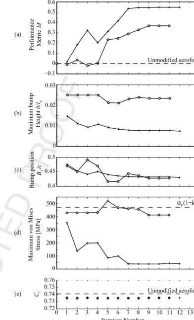
D,this met-ricwillprovideinsightintohowdifferentadaptiveSCBgeometries impact the local aerofoil pressure gradient. This will facilitate a uniqueflow-physics-basedapproachtodesigning aero-structurally optimisedadaptiveSCBs.Fig. 10.Keyperformancedatathroughtheiterationsoftheoptimisationprocedure. a)Performancemetric.b)Bumpheight.c)Bumpposition.d)MaximumvonMises stress.e)LiftcoefficientwithinadaptiveSCB.Wherepresented,iteration0marks theunmodifiedaerofoil.
3. Results
3.1. OptimaladaptiveSCBdesigns
The aero-structural optimisation procedure took on average eight iterations to produce an optimal design. Optimisation con-vergence was defined to have occurred when the change to the performancemetricbetweeniterationsfellbelow0.1%.Thedesign variables explored the design space via the centred finite differ-enceschemewhichresultedin15initialperturbationstothe ini-tialconditions.
Fig. 10showsthe variation ofkey parameters throughout the optimisation process from two initial conditions that represent SCBswithdifferentinitialheights.Forbothinitial conditions pre-sented,themostinfluentialdecisionvariablewasSCBposition B1.
Inbothcases,theSCBpositionconvergestox
/
c≈
0.
43 which cor-responds to a configuration with the shockon the front surface (ramp)oftheSCB.TheoptimiserrecognisesthedominanceofSCB location andtheevolution ofoptimalSCBplacementcan beseen inFig. 10c.Table2 showstheinitial conditionssubmitted to the1 67 2 68 3 69 4 70 5 71 6 72 7 73 8 74 9 75 10 76 11 77 12 78 13 79 14 80 15 81 16 82 17 83 18 84 19 85 20 86 21 87 22 88 23 89 24 90 25 91 26 92 27 93 28 94 29 95 30 96 31 97 32 98 33 99 34 100 35 101 36 102 37 103 38 104 39 105 40 106 41 107 42 108 43 109 44 110 45 111 46 112 47 113 48 114 49 115 50 116 51 117 52 118 53 119 54 120 55 121 56 122 57 123 58 124 59 125 60 126 61 127 62 128 63 129 64 130 65 131 66 132 Table 2
OptimalSCBdecisionvariablesfortheinitialconditionandoptimalsolutionwith2pointsofactuation.The‘optimalsolution’isdefinedasthegeometrycorrespondingto iteration12withthesmallbumpinitialconditionsinFig.10.Thebumplength
l
b=0.2c.B1/c x1/lb δ1/lb x2/lb δ2/lb σmax(MPa) M
Initial condition 0.47 0.5 0.01500 0.55 0.01500 308.4 0
Optimal solution 0.43 0.25 0.00725 0.5 0.00745 170.0 0.55
Fig. 11.(a)GeometryoftheaerofoiluppersurfacewiththeoptimisedadaptiveSCBdeployed;(b)MachnumbercontoursfortheoptimalSCB;(c)Pressurecoefficientprofiles fortheaerofoilwithandwithouttheoptimalSCB.Flowconditions
α
=3.19◦,M
∞=0.728,Re
=6.5×10⁶.optimiser(for theshorterofthetwo initialSCBs) andthe subse-quentoptimalsolution.
Theperformancemetricprovedtobesensitivetothepresence of an SCB which supported its utilisation. The strong correlation between plots (a) and (c) in Fig. 10 confirms that bump posi-tion has the greatest effect upon performance primarily due to thechangeinshockstructurearoundtheSCBcrest.Thestructural constraintset at max
(
σ
v M)
<
σ
y(
1−
k)
is shown to successfullyinfluence thedesign in Fig.10d. Oncethe optimiser iterates and produces a design that exceeds the yield stress, such as itera-tion 5of thetall bump initial condition, thedesign is penalised. Thelateriterationsdonotexceedthisfailurecriterion,illustrating theconstraint’spurposewithintheoptimisationprocedure.Finally, Fig. 10e shows that the effects on the overall lift coefficient are minimal,witha small(lessthan 1%)decreaserelative tothe un-modifiedRAE-2822aerofoilforalliterations.
Fig.11 presentsinformation on thegeometry andflow struc-tureassociatedwiththeoptimaladaptiveSCB.Fig. 11aillustrates howtheoptimalSCBgeometry(withpressureloading)consistsof aregionofhighconcavecurvaturearoundthefrontofthecontrol region, followed by an extended region of more gradual convex curvaturewithaninflectionpoint aroundhalfwayalongtheSCB. Interestingly,suchan inflection pointhasneverbeenobservedin optimalsolutions determinedbyother optimisationstudiesin lit-eraturethat haveconsideredfixed geometrySCBs.Comparison of theSCBgeometrywithandwithoutaerodynamicpressureloading
inFig.11arevealshowthisuniqueshapeiscausedby the differ-ential pressure loadingon the front and rear flexible surfaces of theSCB.TheregionoflowpressureoverthefrontoftheSCB sig-nificantly increases the displacement and stresses in this region, particularlyattheclampedend.Thepeakstressisobservedto oc-cur at the leading edge of the SCB (x
/
c=
0.
43) as a combined resultofthepressureanddisplacementloading.TheMach numbercontoursinFig.11brevealthattheoptimal SCBsuccessfullygeneratestheclassicbifurcated
λ
shockstructure withminimalre-accelerationofthepost-shockflow overtherear half of the SCB.This is attributed to the presence of the inflec-tionpointandsubsequentconcavecurvatureataroundx/
lb≈
0.
5,followed by an extended region of gentle convex curvature over thedownstreamhalfoftheSCB.ThepressureprofileinFig.11cis consistentwiththisobservationandalsoneatlyillustrateshowthe SCBonlyinfluencestheflowlocaltotheimposeddeformation,as expected.
Fig.10bshowsthatastheoptimiserprogressestowardsan op-timalsolution,theactuationheightactuallydecreasesslightly.For both presentedaero-structuraloptima, theplates exhibit a maxi-mumstressthatiswithintheyieldstressofthematerial(Fig.10d). ThisconfirmsthatitisfeasibletoproducefunctionaladaptiveSCB solutions usingexistingaerospacegradematerials withoutplastic deformation.The positionofthecrest withrespecttothestartof thebump (asdefinedby theparameters x1 andx2),hadlittle
ef-1 67 2 68 3 69 4 70 5 71 6 72 7 73 8 74 9 75 10 76 11 77 12 78 13 79 14 80 15 81 16 82 17 83 18 84 19 85 20 86 21 87 22 88 23 89 24 90 25 91 26 92 27 93 28 94 29 95 30 96 31 97 32 98 33 99 34 100 35 101 36 102 37 103 38 104 39 105 40 106 41 107 42 108 43 109 44 110 45 111 46 112 47 113 48 114 49 115 50 116 51 117 52 118 53 119 54 120 55 121 56 122 57 123 58 124 59 125 60 126 61 127 62 128 63 129 64 130 65 131 66 132
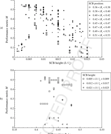
Fig. 12.Variation of performance metricMwith SCB height and position for a range of optimal and sub-optimal designs.
fect onthe performance metric withno correlation found inthe rangeofvaluespermitted.
SCBperformance over a rangeofSCB heightsisan important question foradaptiveSCB that needs tobe answered in orderto predict aerodynamic performance during SCB deployment or re-traction.Toinvestigatethis, a parametric studyexploringthe de-signspacehasbeencarriedoutandtheresultsarereportedinthe followingsection.
3.2.Sub-optimalperformance
Non-optimal solutions encountered during the optimisation process provide a wealth of information abouthow each design parameterinfluencesoverallperformance,asmeasuredbythe per-formancemetricM.Resultsfromtheseintermediate(sub-optimal) iterationsprovidealargedatabankofvaluableandphysicallyvalid (i.e.converged)resultsthatcanbeexploredtogivefurtherinsight intothebehaviour ofadaptive SCBs.Thisapproach alsohas rele-vanceto understandinghowadaptiveSCBsmightbestbe utilised inscenarioswherearangeofflowconditionsareexpected.For ex-ample,duringcruise,aircraftareoftenrequiredtovaryspeedand altitudeandthesemanoeuvresarelikelytochangeshocklocation withrespecttoanySCBinstalledonawing [6].Clearly,beingable tovarySCBgeometrytoaccommodatesuch changesisan advan-tageuniquetoadaptivedevices.
Asmentionedpreviously,themostinfluentialvariableinoverall bumpperformanceisSCBlocation,inparticularthepositionofthe
shockrelative tothe crest ofthe SCB.Thisdependencyhas been widelyreportedinpreviousliterature [8,10].SCBheightisanother parameter which strongly influences the flow over the SCB and thus the overall performance for a given SCBlocation. For these reasons, Fig. 12 presents the variation of performance metric M against SCB height andSCB position for resultsfrom a selection oftheoptimisationperturbations andaparametricstudy.Ineach plot,resultsaregroupedwithrespecttoeitherSCBpositionorSCB height tofurther explorethe relationshipbetweenthese two pa-rameters.The limitsimposed bythe structuralconstraintwere in placeduringalltheperturbationsandonlyresultsfornon-yielding solutionsareshown.
The main trend evident in Fig. 12a is that shorter SCBs have better performancethan tallerSCBs withtheperformance metric dropping almost linearly from a peak of around 0.55 to 0 with increasing SCB height.An exception to thistrend isobserved for smallactuationheights(typically
δ/
lb<
0.
004)whereperformanceispoor.Thisobserved behaviourcan beexplained byconsidering the shock structure formed by different height SCBs. Very small displacements (0
< δ/
lb<
0.
004) give rise to a small amount ofpressuresmearingbutdonot leadtotheformationofaclear bi-furcated
λ
-shock. In contrast, almost all test cases with an SCB heightδ/
lb>
0.
004 causeawell-definedbifurcatedλ
-shockstruc-ture,leadingtoasignificantincreaseinpressuresmearing.Atlarge SCBheights, thisbenefitisoffsetby strongre-accelerationofthe post-shockflow(similartocase3inFig.9),whichultimatelyleads
1 67 2 68 3 69 4 70 5 71 6 72 7 73 8 74 9 75 10 76 11 77 12 78 13 79 14 80 15 81 16 82 17 83 18 84 19 85 20 86 21 87 22 88 23 89 24 90 25 91 26 92 27 93 28 94 29 95 30 96 31 97 32 98 33 99 34 100 35 101 36 102 37 103 38 104 39 105 40 106 41 107 42 108 43 109 44 110 45 111 46 112 47 113 48 114 49 115 50 116 51 117 52 118 53 119 54 120 55 121 56 122 57 123 58 124 59 125 60 126 61 127 62 128 63 129 64 130 65 131 66 132
Fig. 13.SurfacepressurecoefficientandwallshearstressprofilesforadaptiveSCBs,with
B
1=0.43 andvariableheight.TheprofilesfortheoptimalSCBwithδ/lb=0.0075arehighlightedwithadashedline.Plots(b)and(c)onlyshowtheregionaroundtheshockwaveontheaerofoiluppersurface.
totheobserveddropintheperformancemetricM.Figs.13and14 (discussedfurtherlater)confirmthepresenceofthisbehaviour.
Fig. 12a also shows that SCB positions in the range 0
.
40<
B1/
c<
0.
45 are consistently amongst the best performers,al-though there is considerable scatter. In contrast, more upstream SCB positions (0
.
36<
B1/
c<
0.
40) always perform relativelypoorly. The step-change in performance at a threshold of
δ/
lb≈
0
.
004 appears to be universal and irrespective of SCB position. Thisbehaviourisattributedtotheaero-structuralresponseofthe flexible surface: as SCB height is increased beyond this thresh-old,movement ofthemainshockwavechanges theaerodynamic pressure loadingin such a waythat causes the upstream halfof the SCB to balloon, attaining a shape similar to the optimal ge-ometry (with pressure loading) shown in Fig. 11a. In this way, even arelatively short SCBcan achieve strong concavecurvature atits leadingedge,whichisthegeometric featureresponsiblefor astrongλ
-shockstructureandassociatedpressuresmearing.These results suggest that short, adaptive SCBs mayhave the potentialtoachievesimilarlevelsof(beneficial)pressuresmearing comparedtotallersolidSCBswhilepotentiallymitigatingsomeof the(detrimental)viscouseffectsassociatedwithtallSCBs.This as-sertionissupportedbytheMachnumbercontoursinFig.11b(also presented as Fig. 14b), which show that the optimal SCB (with
δ/
lb=
0.
0075) places the rear leg of theλ
-shock at x/
c≈
0.
50which is juston the front surface ofthe SCB (x
/
lb≈
0.
40). Thisplacement with respect to the shockis sympathetic to the flow as it provides a small region of concave curvature immediately downstreamoftheshockfollowedbyalongextentofverygradual convexcurvature.Thisminimisesthelikelihoodofseparationand re-accelerationofthepost-shockflow,inagreementwithpressure profilesinFig.13.
Fig.12bexplorestheeffectofSCBpositionB1 onperformance.
OnlyasubsetoftheresultsinFig.12aarereproducedinFig.12b: groupedintothreedistinctheight ranges,all ofwhichexceedthe thresholdidentifiedinFig.12a.Theplotdoesnotshowauniversal trendbetweenSCBpositionandperformance,andratherconfirms thattheperformancemetricismoresensitivetoactuationheight,
with a clear banding of the results for the three different SCB heightrangesconsidered.
The shortest SCBs (0
.
005< δ/
lb<
0.
009) show the strongestsensitivitytoSCBposition,withajumpintheperformancemetric from
≈
0.
25→
0.
50 whenB1/
cexceeds≈
0.
42.Goodperformanceismaintainedfor0
.
43<
B1/
c<
0.
46 beforeasubsequentgradualdecrease in performance is observed for B1
/
c>
0.
46. Moderateheight SCBs (0
.
012< δ/
lb<
0.
017) alsoshow some sensitivity toSCB position. However, unlike the shorter devices, performance is highest for the upstream SCB positions anddecreases as SCB positionmovesdownstream.Thissuggeststhatrelativelygood per-formancecanbeachievedwithmoderatelytallSCBsprovidingthe SCBisoptimallypositioned(0
.
40<
B1<
0.
43c).However, arapiddrop-offinperformanceisobservedforSCBpositionsoutsidethis range.Finally,thetallestSCBs(0
.
021< δ/
lb<
0.
025)showverylit-tlesensitivitytoSCBposition,andconfirmthetrendfromFig.12a that the performance ofadaptive SCBs degradeswithfurther in-creasingactuationheight.
The sensitivityoftheflowtoshockposition(andmore specif-ically crest location) previously reported by [10] is broadly con-sistent with the results for the short and moderate height SCBs presentedinFig. 12b.SCBpositioneffectivelydetermines the po-sition ofthe bump crest relative tothe main shockwave on the aerofoil,calculated tobe atx
/
c=
0.
495 forthe unmodified aero-foil.Thebest performingbumpsarethosewithaleading edgein the range 0.
43≤
B1≤
0.
45c corresponding to crest locationsintherange0
.
51≤
x/
c≤
0.
58.Inallcasesthisyieldsa scenario wheretherearlegoftheλ
-shocksitsonthefrontfaceoftheSCB withsubsonicflowovertherearfaceoftheSCB:anadvantageous arrangementasdiscussedpreviously.Figs. 13 and 14 show the effect of SCB height on the sur-facepressure,skinfrictionandMachnumberdistributionsaround the aerofoil. All results in these figures were obtained with an SCB position matching that of the optimal SCB discussed earlier (B1
/
c=
0.
43)forSCBheightsintherange0.
005< δ/
lb<
0.
020.The pressure profiles in Fig. 13 highlight how large actua-tor displacements produce SCB shapes that cause significant
re-1 67 2 68 3 69 4 70 5 71 6 72 7 73 8 74 9 75 10 76 11 77 12 78 13 79 14 80 15 81 16 82 17 83 18 84 19 85 20 86 21 87 22 88 23 89 24 90 25 91 26 92 27 93 28 94 29 95 30 96 31 97 32 98 33 99 34 100 35 101 36 102 37 103 38 104 39 105 40 106 41 107 42 108 43 109 44 110 45 111 46 112 47 113 48 114 49 115 50 116 51 117 52 118 53 119 54 120 55 121 56 122 57 123 58 124 59 125 60 126 61 127 62 128 63 129 64 130 65 131 66 132
Fig. 14.MachnumbercontoursaroundtheaerofoilwithdifferentSCBheightsin therange0.005< δ/lb<0.020 andanSCBlocation B1/c=0.43.TheMach
num-bercontoursin(b)matchthosepresentedinFig.11fortheoptimalSCB,butare presentedherewithaslightlydifferentcolourscale.
Fig. 15.L/Dvariationforincreasingbumpheight.CleanaerofoilL/Dratioincluded forcomparison.
acceleration of the post-shock flow over the SCB crest and ex-tensive regions of low pressure between 0
.
51<
x/
c<
0.
61. The wall shear stress in Fig. 13c drops below zero around the SCB crest(x/
c≈
0.
52) foreachofthethree tallestgeometries, indica-tiveoftheonsetofflow separation.Anadditionalregionof sepa-ratedflowispresentaroundtheupstreamedgeofthetallestSCB (δ/
lb=
0.
0200).Inallcases,theonsetofseparationisclearlycor-relatedtothe strength ofthe adverse pressuregradient. No flow separationisobservedfortheoptimal(
δ/
lb=
0.
0075) orsmallest(
δ/
lb=
0.
0050)displacementcases.The pressure around the most upstream extent of the con-trolregion(x
/
c≈
0.
43) showsa strongdependency onactuation height.Increasingactuationleadstoalargerangleofthefrontsur-face oftheSCB, whichgovernsthe strengthofthe initialoblique shock (
λ
-shock front leg) and associated pressure gradient. The strength of thisinitial oblique shock determines the Mach num-beroverthefrontsurfaceoftheSCBandhencethestrengthoftheλ
-shockrearleg.ThisinterdependencyisclearlyshowninFig.13c, wherethemagnitudeofthesecond risein Cp around x/
c≈
0.
48is inversely proportional to the size of the initial rise ataround x
/
c≈
0.
43.Optimumperformanceisachievedwhenthefirst pres-sure rise is quite small. This corresponds to a reasonably strongλ
-shockrearleg,whichensuresthat thepost-shockflowis decel-eratedsignificantlybelowMach 1beforeitreachestheSCBcrest. Thisfeature,togetherwiththegentlecurvatureofthedownstream surfaceoftheoptimalSCB,avoidsre-accelerationofthepost-shock flowtosupersonicvelocities.Incontrast,thetallerSCBsgeneratedwithgreateractuation in-cur a weak
λ
-shock rear leg which resultsin a post-shockMach number very closeto 1 for the flow approaching the SCB crest, and ultimately re-acceleration to supersonic velocities and sec-ondary shock waves. Close inspection of the pressure andMach number distributions reveal that theλ
-shock rear-legmoves for-wardsslightlywithincreasingactuationheight,whichexposesthe post-shockflowtogreatercurvatureoverthecrest.3.2.1. Globalaerodynamicperformance
The aero-structurally optimised adaptive SCB does not cause the flow to separate over the SCBcrest. This is a reassuring re-sultwhichsupportsthechoiceofthepressuregradient-based per-formance metricasa tool foridentifying promisingadaptive SCB designsthat havea favourableimpactonflow qualityinthe con-trolregion.Inthissection,weconsidertheimpact ofthe applied control on the globalperformance metric L
/
D, to further assess thepotentialofadaptiveSCBsandfacilitatecomparisonwithother (fixedgeometry)SCBoptimisationstudies [6,10,26,29,30].Fig. 15showsthe variation of L
/
D forthe aerofoil with opti-mallypositionedadaptiveSCBs(B1/
c=
0.
43)withthesamerangeofheightsconsidered in Figs.13 and14.The plotshowsthat all SCBsresultinasmalldecreaseinL
/
D relativeto theunmodified RAE-2822aerofoil. The largestdrop in L/
D occursforthe tallest SCB(δ/
lb=
0.
020): almost 1% relativetothe unmodifiedaerofoil.For the optimalSCB (
δ/
lb=
0.
0075), the drop in L/
D is≈
0.
3%.This change actually consistsof a small decrease in Cd of
≈
0.
5%thatisunfortunatelyoffsetbyaloss inCl of
≈
0.
8%,aspresentedpreviouslyinFig.10e.
These numbersare unremarkable if comparedto headline re-sults fromother studies that have suggested SCBs may augment L
/
D by as much as 10% or more at certain operating condi-tions [6,10].However,theydoconfirmthattheadditionofan aero-structurallyoptimised adaptiveSCBcan haveafavourableimpact on flow quality inthe shock region without having a significant adverse affect onglobal aerofoilperformance. This implies adap-tive SCBsmay havepotential asaflow control device tofaciliate the design of aerofoils withstrong shock waves,such as a tran-soniclaminarflowaerofoil.4. Conclusions
A computational study to design an adaptive shock control bump(SCB)foratransonicaerofoilhasbeenperformed.Thestudy hasutilisedaerodynamicandstructuralcomputational(FEA)tools to capture the flow physics of the fluid-structure interaction on an actuatedflexible portionofthe uppersurface ofan RAE-2822 transonic aerofoil.Anovel performancemetricbasedon thelocal surface-pressuregradientintheshock-region(ratherthanaglobal aerodynamic performance metric such as L
/
D or Cd) is used to1 67 2 68 3 69 4 70 5 71 6 72 7 73 8 74 9 75 10 76 11 77 12 78 13 79 14 80 15 81 16 82 17 83 18 84 19 85 20 86 21 87 22 88 23 89 24 90 25 91 26 92 27 93 28 94 29 95 30 96 31 97 32 98 33 99 34 100 35 101 36 102 37 103 38 104 39 105 40 106 41 107 42 108 43 109 44 110 45 111 46 112 47 113 48 114 49 115 50 116 51 117 52 118 53 119 54 120 55 121 56 122 57 123 58 124 59 125 60 126 61 127 62 128 63 129 64 130 65 131 66 132
The performance metric successfully guides the optimisation processtoproduce an adaptiveSCBgeometrythatbifurcatesthe shock on the aerofoil to form a
λ
-shock structure with signifi-cantbeneficialpressure-smearing intheshock-region.Inaddition to the(active) fixed displacement constraints,the (passive) aero-dynamicpressureforce ontheflexiblesurface playsan important role in achievingthis geometry, which exhibits a shape that is uniqueto adaptiveSCBs:the resultant geometryischaracterised by (1) a moderate amount of concave curvature at the leading edge; (2) a convex ramp with maximum height at around 40% ofthebump length; (3)an inflection pointataround 50% ofthe bumplengthwhichintroducesconcavecurvature;(4)anextended region of gentle convexcurvature over the rear half ofthe SCB; (5) gentleconcavecurvatureatthetrailingedge.The upstream halfof the SCBgeometrybifurcates the shock, while the crest and downstream half are responsible for care-fulmanagement oftherecovering post-shockflow. Optimal pres-sure smearing occurs when the initial compression around the SCBleadingedgeisrelativelyweak,whichisachievedwithsmall displacement heights. At thiscondition, separation along the en-tireSCBlengthisavoided,despitetherelativelyhighuncontrolled shockstrength(Mclean
≈
1.
25).The adaptiveSCByieldsadecreaseinoverall drag of
≈
0.
5%, although thisis offsetby a dropin lift of0.
8%,givinga smalloveralldropin L/
D of0.
3%.These results suggest adaptive SCBs are particularly well-suited to geometries wherea strong shockwave isunavoidable, such ason a laminar flow wing;a conclusionin commonwithconventional (fixed ge-ometry)SCBs.A parametric studyof adaptive SCB designs reveals a unique dependenceofperformanceontheimposeddisplacement(height) of the device: shorter (less tall) SCBs generally perform better than taller ones, andmaintain their performance advantage over a wider range of SCB positions. This suggests such devices are likely to exhibit good robustness to variations in shock position (which are an inevitable feature of anyreal-world flight applica-tion);aresultthat isincontrasttoconventional (fixedgeometry) SCBs,whereoptimalperformance(commonly definedin termsof dragsavingorsimilar)isachievedwithtallerSCBs,attheexpense ofpoorrobustnesstovariations inshockposition.Finally,the po-tentialof adaptiveSCBs to achieve good performance with small imposeddisplacementsisattractive withrespecttopractical con-siderationsthatincludefatigueloading:smalldisplacementsavoid highstresses (in either the flexible surface material or actuation mechanism)andthusprolongthelifeofthesystem.
Conflictofintereststatement Nonedeclared.
Acknowledgements
The first author would like to thank the UK Engineering and Physical SciencesResearch Councilwho provided fundingforthis work.
References
[1] P.Ashill,J.L.Fulker,A.Shires,Anoveltechniqueforcontrolling shockstrength oflaminar-flowaerofoilsections,in:FirstEuropeanForumonLaminarFlow Technology,1992,pp. 175–183.
[2] E.Stanewsky,J.Délery,J.L.Fulker,P.deMatteis,DragReduction byShockand BoundaryLayerControl:ResultsoftheProjectEUROSHOCKII,Springer,2002. [3] E.W.MillholenII,R.L.Owens,Ontheapplicationofcontourbumpsfor
tran-sonicdragreduction(invited),AIAAJ.0462(2005)1–19.
[4] H.Ogawa, H.Babinsky, Evaluation ofwavedragreduction byflowcontrol, Aerosp.Sci.Technol.10 (1)(2006)1–8.
[5] J.Birkemeyer, H. Rosemann,E.Stanewsky, Shockcontrol on aswept wing, Aerosp.Sci.Technol.4 (3)(2000)147–156.
[6] J.Eastwood,J.P.Jarrett,Towarddesigningwith three-dimensionalbumpsfor lift/dragimprovementandbuffetalleviation,AIAAJ.50 (12)(2012)2882–2898. [7] S.P.Colliss,H.Babinsky,K.Nübler,T.Lutz,Jointexperimentaland numerical approachtothree-dimensionalshockcontrol bumpresearch,AIAAJ.52 (2) (2014)436–446.
[8] P.J.K.Bruce,H.Babinsky,Anexperimentalstudyintotheflowphysicsof three-dimensionalshockcontrolbumps,J.Aircr.49 (5)(2012)1222–1233. [9] P.J.K.Bruce,S.P.Colliss,Reviewofresearchintoshockcontrolbumps,Shock
Waves25 (5)(2015)451–471.
[10] N.Qin,W.S.Wong,A.LeMoigne,Three-dimensionalcontourbumpsfor tran-sonicwingdragreduction,Proc.Inst.Mech.Eng.,PartG:J.Aerosp.Eng.222 (5) (2008)619–629.
[11] S.P. Colliss, H. Babinsky, K. Nübler, T. Lutz, Vortical structures on three-dimensionalshockcontrolbumps,in:51stAIAAAerospaceSciencesMeeting includingtheNewHorizonsForumandAerospaceExposition,January,AIAA, Grapevine(Dallas/Ft.WorthRegion),Texas,2013,pp. 1–15.
[12] T. Lutz,A.Sommerer,S.Wagner,Parallelnumerical optimisationofadaptive transonicairfoils,in:IUTAMSymposium–TransonicumIV,KluwerAcademic Publishers,2003,pp. 265–270.
[13] W.Wadehn,A.Sommerer,T.Lutz,D.Fokin,G.Pritschow,S. Wagner, Struc-turalconceptsandaerodynamicdesignofshockcontrolbumps,in:ICAS2002 Congress,2002.
[14] O.Rhodes,M.Santer,Aeroelasticoptimizationofamorphing2Dshock con-trolbump,in:53rdAIAA/ASME/ASCE/AHS/ASCStructures,StructuralDynamics andMaterialsConference20thAI,23–26April2012,Honolulu,Hawaii,AIAA 2012-1440,2012,pp. 1–17.
[15] M.Visbal,Ontheinteractionofanobliqueshockwithaflexiblepanel,J.Fluids Struct.30(2012)219–225.
[16] M.Visbal,Viscousandinviscidinteractionsofanobliqueshockwithaflexible panel,J.FluidsStruct.48(2014)27–45.
[17] V.Pasquariello,S.Hickel,N.Adams,G.Hammerl,W.Wall,D.Daub,S.Willems, A.Guelhan,Coupledsimulationofshock-wave/turbulentboundary-layer inter-actionoveraflexible panel,in:6thEuropeanConferenceforAerospace Sci-ences,2015.
[18] E.Jinks,P.J.K.Bruce,M.Santer,Windtunnelexperimentswithflexibleplates intransonicflow,in:54thAIAAAerospaceSciencesMeetingatAIAASciTech, January,AIAA,SanDiego,CA,USA,2016.
[19] ABAQUS,DassaultSystèmes,Providence,RI,USA,2007.
[20] AGARD-AR-138, Experimental DataBase forComputer ProgramAssessment, Tech.rep.,NATOAdvisoryGroupforAerospaceResearchandDevelopment. [21] OpenFOAM,www.openfoam.org,2017.(Accessed 12February2017). [22] P.Spalart,S.Allmaras,Aone-equationturbulencemodelforaerodynamicflows,
in:30thAerospaceSciencesMeetingandExhibit,Reno,Nevada,1992,0439. [23] P.Cook,M.McDonald,M.Firmin,AerofoilRAE2822–PressureDistributions,
and Boundary Layer and WakeMeasurements, Experimental Data Base for ComputerProgramAssessment,AGARDReportAR138.
[24] H.Ogawa,H.Babinsky,M.Patzold,T.Lutz,Shock-wave/boundary-layer interac-tioncontrolusingthree-dimensionalbumpsfortransonicwings,AIAAJ.46 (6) (2008)1442–1452.
[25] O.Rhodes,OptimalDesignofMorphingStructures,Phdthesis,ImperialCollege London,2012.
[26] B.Yagiz,O.Kandil,Y.V.Pehlivanoglu,Dragminimizationusingactiveand pas-siveflowcontroltechniques,Aerosp.Sci.Technol.17 (1)(2012)21–31. [27] D.Lee,G.Bugeda,J.Periaux,E.Onate,Robustactiveshockcontrolbumpdesign
optimisationusinghybridparallelMOGA,Comput.Fluids80(2013)214–224. [28] M.Kutzbach,T.Lutz,S.Wagner,Investigationsonshockcontrolbumpsfor
infi-nitesweptwings,in:2ndAIAAFlowControlConference,June27–July1,2004, Portland,OR,2004,pp. 1–10.
[29] D.S.Lee,L.F.Gonzalez,J.Periaux,G.Bugeda,Double-shockcontrolbumpdesign optimizationusinghybridizedevolutionaryalgorithms,Proc.Inst.Mech.Eng., PartG:J.Aerosp.Eng.225 (10)(2011)1175–1192.
[30] D.S.Lee,J.Periaux,E.Onate,L.F.Gonzalez,N.Qin,Activetransonicaerofoil de-signoptimizationusingrobustmultiobjectiveevolutionaryalgorithms,J.Aircr. 48 (3)(2011)1084–1094.
![Fig. 1. Illustration of expected actuator loading and initial sizings. Adapted from [1].](https://thumb-us.123doks.com/thumbv2/123dok_us/1881347.2774648/2.918.102.390.95.154/fig-illustration-expected-actuator-loading-initial-sizings-adapted.webp)