ICCAS 2011, 20 - 22 September 2011, Trieste, Italy
© 2011: The Royal Institution of Naval Architects
A PROCESS FOCUSED APPROACH TO ERP INTEGRATION WITH CAD
Written by: Darren Larkins, ShipConstructor Software Inc., CanadaPatrick Roberts, ShipConstructor Software USA Inc., USA SUMMARY
Shipbuilding CAD/CAM systems are a rich source of data that can be consumed by other business processes. In shipbuilding, managing and tracking the procurement and consumption of materials via an Enterprise Resource Planning (ERP) system is a critical portion of a shipyard’s overall IT infrastructure. ERP systems are data hungry applications and while the technology to integrate these systems is usually available, an in-depth understanding of the shipyard’s business processes and how those processes map onto an integration effort is a necessary, yet often lacking, component of a successful integration project. This paper outlines an effort, undertaken by ShipConstructor Software Inc. (SSI), to solve this challenge for a diverse array of shipbuilders.
NOMENCLATURE
CAD – Computer Aided Design CAM – Computer Aided Manufacturing XML – Extensible Markup Language XSD – XML Schema Definition ERP – Enterprise Resource Planning PDM – Product Data Model
IT – Information Technology
IDEF0 – Integration Definition for Function Modelling SSI – ShipConstructor Software Inc.
MBOM – Manufacturing Bill of Materials SOW – Statement of Work
SC – ShipConstructor
PWBS – Product Work Breakdown Structure DLL – Dynamic-Link Library
1. INTRODUCTION
As part of a consolidated effort to successfully integrate ShipConstructor into the ERP systems chosen by a number of clients, ShipConstructor Software Inc. (SSI) underwent a repeatable process to identify a shipyard’s business processes and map those processes using the IDEF0 functional modelling methodology. The work was performed at a number of ShipConstructor clients currently using a diverse array of ERP systems. The variety of shipbuilders, business processes and ERP systems involved allowed SSI to define a neutral format data alignment map designed to allow the mapping of data between ShipConstructor and virtually any ERP system. During the course of the effort, and as an on-going part of SSI’s commitment to allowing each client to select the best tools for the individual parts of their IT infrastructure, SSI developed a toolset that exports engineering data to a neutral XML schema that conforms to the created data alignment map. The method followed and the approach taken by SSI has allowed for a broad range of ERP systems to be integrated with ShipConstructor. The process for implementation has been well documented such that it could be replicated by SSI personnel and then applied specifically to any organization that has selected ShipConstructor as its CAD system where a requirement exists to exchange data with their selected ERP system.
1.1 CAD TO ERP INTEGRATION
CAD systems, as the originators of much of the data about a project, are by definition data rich environments. A CAD system is initially where all the individual ship parts and components are brought to life in a data rich “virtual world” as it will one day be represented as a tangible / physical object on board a constructed and delivered ship. A large amount of technical information is gathered from vender furnished information, drawings, catalogue cut sheets, operations manuals and contained within a CAD system. CAD systems are also the most “current” place for data to be captured and contained in an as designed state. ERP systems on the other hand are data hungry and can bring the most value when they are populated with as much data as can be managed successfully. The challenge this introduces is in determining an appropriate way in which the CAD data can be consumed. Key considerations include how and if a specific piece of data should be translated for its new environment and what level of data should be transferred in order to ensure that sufficient data is available to the ERP system without introducing the unwanted complexity that can result from transferring too much data in an unstructured fashion.
2. PROJECT METHODOLOGY
Integrating CAD tools with ERP isn’t a new requirement for businesses; shipbuilding is no exception. Integration projects have been undertaken by shipyards in the past though often with mixed results. These results range from successful implementations (with lessons learned for the next iteration) to failed ventures that for many reasons are not completed. Most fall somewhere between. While successful by some metrics, they often do not satisfy the entire needs of the organization.
Whether integrating new ERP systems into an existing ShipConstructor environment or vice versa, SSI noticed a common theme. An understanding of business processes was critical. The technology to exchange data on both sides of the equation was sufficient since modern CAD, PLM, and ERP systems provide enough integration
However, technology itself was not a barrier. With ShipConstructor in particular the combination of an AutoCAD / DWG platform, industry standard Microsoft SQL Server database, and several developer APIs ensured that the available technology would not be an issue. With technology having been eliminated as a factor, it became apparent that what was missing was a documented and understood map of an organization’s business processes that create and consume information relevant to a CAD to ERP integration.
With this understanding in hand, SSI proposed a collaborative effort with the following goals:
Implement a methodology to clearly map the business processes involved, including inputs, outputs, controls, and the underlying mechanisms at each step for a variety of shipyards, using a range of ERP systems Develop a data alignment map for each
shipyard that identified the common interface points between ShipConstructor and the ERP system of choice
Develop a neutral exchange format for ERP interchange with CAD that combined the data alignment map for all of the shipyards and their various ERP systems
These goals are explained more fully below.
2.1 BUSINESS PROCESS MAPPING
While many of the shipyards had processes that were understood by those following them, few had truly documented those processes such that they could be mapped into an integration project between their CAD and ERP tools. Formalization of the processes offered a significant opportunity to improve the current processes in place. In order to take advantage of this opportunity it was necessary to model the “As-Is” process at the shipyards as a platform for the intended “To-Be” process that would be implemented in conjunction with the CAD-ERP integration effort. It was determined that the process modelling effort had to be performed in a structured, repeatable fashion that could be readily consumed by the subsequent stages in the effort.
2.2 DATA ALIGNMENT MAP
Once the business processes had been mapped it was necessary to identify the specific data fields that existed in the target CAD and ERP systems. The process map that was developed in the first stage of the project work scope proved sufficient to define how each piece of data in the CAD system, as an input to an external process,
place in the ERP system.
2.3 NEUTRAL DATA DEFINITION
The final deliverable of the project effort was a toolset that exports a set of data from ShipConstructor in such a way that it contains enough information (and no more), presented in an accessible fashion, to allow ShipConstructor to be integrated with a range of ERP systems at a variety of shipyards with different processes. This was achieved through the definition of a neutral data format and the creation of a set of tools within ShipConstructor that can export data to that neutral format.
3. PROJECT IMPLEMENTATION
3.1 TARGETED CAD SYSTEMS
The project primarily focused on integrating a range of ERP systems with ShipConstructor. ShipConstructor is an AutoCAD based CAD/CAM software suite that provides detail design and modelling tools for production engineering of marine structures. ShipConstructor captures all information relevant to the 3D design, manufacturing, repair and refit of complex marine projects in a single integrated 3D product model. At the heart of the model is a single relational database residing on a Microsoft SQL Server that can be integrated with related business processes and applications.
Although this project primarily focused on ShipConstructor in regards to specific data contained within the CAD/CAM software tool, the shipyards involved in this project also had legacy CAD systems they were maintaining. These other CAD systems were also considered within the business processes and 3D product model data requirements captured.
3.2 TARGETED ERP SYSTEMS
The shipyards involved in the project utilize the following set of ERP systems:
IFS
AVEVA MARS
ORACLE E-Business
Infor Baan
These ERP systems represent a cross section of the most common types of ERP systems used in shipbuilding including shipbuilding focused, project-centric and traditional enterprise level ERP systems. They also represent a wide array of different technologies and recommended integration approaches.
ICCAS 2011, 20 - 22 September 2011, Trieste, Italy
© 2011: The Royal Institution of Naval Architects The shipyards involved in the project are all located in the United States and have all worked collaboratively with SSI and each other on prior projects. This history of cooperation was critical as the project required a high degree of collaboration in order to be successful. The shipyards are all of varying size, work on commercial and/or naval projects, build vessels of varying sizes, and have significantly different processes. Together they form a representative cross section of the US shipbuilding market. The shipyards that were involved in the project are listed below.
3.3 (a) Huntington Ingalls Industries
Huntington Ingalls Industries (HII) designs, builds and maintains nuclear and non-nuclear ships for the U.S. Navy and Coast Guard and provides after-market services for military ships around the globe. For more than a century, HII has built more ships in more ship classes than any other U.S. naval shipbuilder. Employing nearly 38,000 in Virginia, Mississippi, Louisiana and California, its primary business divisions are Newport News Shipbuilding and Ingalls Shipbuilding. ERP system: MARS.
3.3 (b) Austal USA, Inc.
With shipyards in Western Australia and the United States of America (Mobile, Alabama), Austal has delivered more than 220 vessels for customers around the world. Austal’s product range includes passenger and vehicle-passenger ferries, patrol boats, theatre support vessels, combat ships, multi-role vessels and luxury private live-aboards. ERP System: IFS.
3.3 (c) VT Halter Marine, Inc.
VT Halter Marine, Inc. is a subsidiary of Vision Technologies Systems, Inc. (VTS) that designs and build maritime products. VT Halter Marine shipyards have an impeccable 50-year tradition of shipbuilding excellence as an internationally-acclaimed shipbuilder, noted for being the largest designer and builder of small to medium-sized ocean-going vessels in the United States for many years. ERP System: MARS.
3.3 (d) Marinette Marine Corp., a Fincantieri company Marinette Marine Corporation (a Fincantieri company) was founded in 1942 along the Menominee River in Marinette, Wisconsin to meet America's growing demand for naval construction. It has designed and built more than 1,500 vessels. Its portfolio includes the U.S. Navy’s Littoral Combat Ship, the improved Navy Lighterage System, mine countermeasure vessels and ocean tugs, as well as U.S. Coast Guard icebreakers, buoy tenders and response vessels. ERP System: Infor Baan.
3.3 (e) Bollinger Shipyards, Inc.
Bollinger Shipyards provides new construction, repair and conversion products and services to the commercial offshore energy and marine transportation markets around the world, and to the U.S. Government and naval shipbuilding marketplace from its U.S. Gulf of Mexico facilities. Family owned and operated since 1946, Bollinger maintains twelve ISO 9001:2008 certified shipyards and a fleet of thirty-one dry-docks for shallow draft and deepwater vessels. ERP System: Oracle E-Business.
3.3 (f) Vigor Shipyards
Vigor Shipyards (formerly Todd Pacific Shipyards) has been serving the marine industry in the northern Pacific since 1916. Vigor Shipyards offers government and commercial customers’ broad expertise in new construction, conversion, and repair. Vigor has been delivering high quality vessels for the Seattle Waterfront, which is one of the world’s largest Maritime Industrial Business Centers in the US. ERP System: IFS.
3.4 PROCESS MAPPING MEETINGS
To map each shipyard’s business process, meetings were conducted at the various shipyard participants’ locations. It was important to conduct these event sessions on location to gain access to key personnel who were warrant holders of the processes that would be discussed. These event sessions were scheduled around the shipyards’ key personnel availability as to not disrupt their normal business operations. SSI was able to offer a flexible schedule to work with the shipyards while maintaining a consistent momentum in capturing their business processes. Several event sessions included a working lunch (“Lunch & Learn” sessions) in efforts to keep engagement at the shipyards. Having all of the key process owners in the modelling sessions allowed for each key process owner to understand their respective co-worker, co-department, and fellow shipyard process owners’ job functions, responsibilities and the steps each person took within their respective portion of the process.
3.5 PROCESS MAPPING METHODOLOGY
A process mapping methodology was required that would allow the project team to map, define, and optimize the business processes in use by the shipyards. Additionally the process definitions needed to be mapped onto the identified data fields and tools created as part of the effort. As a result the IDEF0 methodology was selected as it applies equally well to manufacturing, lifecycle processes and software engineering tasks.
IDEF0 (Integration Definition for Function Modeling) is a function modeling methodology for describing manufacturing functions. It offers a functional modeling language for the analysis, development, reengineering, and integration of information systems, business processes, or software engineering analysis. IDEF0 is used to show data flow, system control, and the functional flow of lifecycle processes.
An overview of IDEF0 methodology shows why it was an ideal tool for this project. IDEF0 helps to facilitate a structured approach in the documentation of the organization’s associated business process activities, descriptions, properties, data sources, costing data, and any special notations. The specific examples of those concepts needed to perform an activity, as well as those concepts that help to move an activity towards a completion state govern a specific output. By nature of the IDEF0 modeling process, an activity’s output normally equates to a document or relative information that serves as an input or control to a subsequent activity within a networked IDEF0 model. Capturing a physical representation of an activity’s output (i.e. document, data or result) produced from its associated mechanisms helps in review and clarification. Capturing the associated business process activities also allows for an understanding of the process and the ability to recall the relative need for the performed activity and the value it brings to the overall business process. Analyzing the IDEF0 model as a whole allows for easy exposure of activities and shows common activities to be combined at an earlier stage within a process model. The facilitation of this continuous process improvement occurs as a result of applying this process modeling methodology.
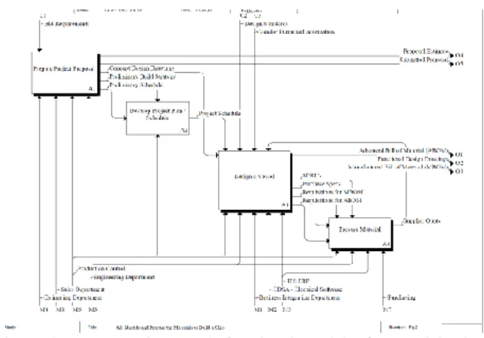
As stated earlier, the SSI team worked with each shipyard to map the existing business processes using the IDEF0 modelling methodology described above. Each team member was provided an overview of the process and modelling definitions, the process that would be carried out, and the rules that would serve in guidance throughout the modelling process. It was stressed to the shipyard representatives that the “As-Is” business process and logic captured had to be correct. An example of the process model for a particular phase of one shipyards’ process can be seen in Figure 2.
Figure 2 An example IDEF0 functional model of a participating shipyard
Each shipyard team involved all notable department representatives and those key individuals that controlled the internal functions and business processes. This was a key element in regards to identification of others understanding where their output became someone else’s input to their activities. SSI as an outsider looking in was able to showcase redundancies, duplications in effort, and possible immediate improvement solutions by walking the key process stakeholders through the IDEF0 modelling effort. With these key stakeholders inside the room, “To-Be” process changes were captured in efforts to streamline and improve processes for a future state. In most cases, these captured business processes relied on some type of data, data input, data communication, and data exchange whether it was manual, semi-automated, or completely automated in some fashion. Mechanisms identified as departments, systems, facilities, tools etc. were all notably evident within the IDEF0 model. This allowed for a focused approach in harvesting the respective data required by the activity to be performed and showed whether that data would be passed onto the next activity based on the inputs or controls from the follow-on associated activities. Capturing the data requirements allowed for initial identification of ERP data needs and the start of the creation of the data alignment map from the CAD system for the shipyard per their specific business processes.
3.6 CREATING THE DATA ALIGNMENT MAP
The next phase of the project required a data alignment map to be developed between ShipConstructor and the target ERP system at each shipyard. The first step in this process was to identify all of the relevant data that existed within the database containing the ShipConstructor Product Data Model (PDM) and the Production, Materials and Planning data contained within the target ERP system database.
The information needed by the Data Alignment Map became apparent as the key process owners revealed their associated inputs, controls, and mechanisms that all went into producing the associated output. Examining the
ICCAS 2011, 20 - 22 September 2011, Trieste, Italy
© 2011: The Royal Institution of Naval Architects documents, policies, procedures, and associated ERP available data elements allowed for the harvesting of all the relative data for the “As-Is” process and the potential data for the “To-Be” process that was contained within the design process outputs. After capturing these data elements and placing them in the Data Alignment Map per the shipyard’s process model and the ERP system employed, SSI was able to also align and compare those specific shipyard business process data with the other shipyards with the same ERP system. Once all of the shipyards have been modelled, and the consolidated ERP data grouping was recognized for each ERP system, the ERP data grouping could then be compared to identify consistencies in the data employed by each ERP system and to discover other data elements that were not being utilized. This allowed for SSI to communicate potential best practices in the data use in a consolidated look. Being able to see all ERP data usage provided the shipyard a chance to revisit their “To-Be” business process and refine it to include identification of certain CAD data within the ShipConstructor database that could be gathered for the ERP neutral data export.
Figure 3 Conceptual Project Diagram
One approach to integrating these two databases would have been to simply compare the relative tables defining their architectures, identify where there was an overlap of data elements and then create a toolset to transfer all data that could be transferred. However, it was realized that a shipyard might not utilize either the ERP or the PDM fully due to the shipyard’s business process not requiring full use of either system. Instead, the project team used the previously identified “As-Is” and “To-Be” process models to identify where a data element from one system should intersect one from the other system through the normal flow of operations in the shipyard. Where such an intersection existed or was desired to exist, the two elements were included in the data alignment map for that shipyard.
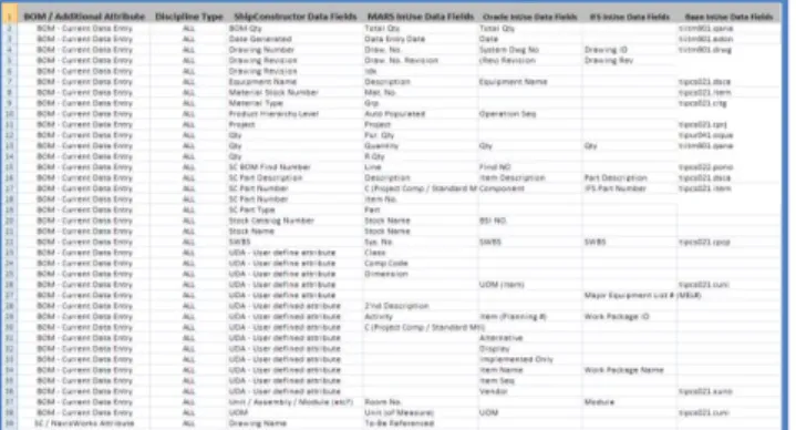
Figure 4 A snapshot from the generated data alignment map
After the completion of the data alignment map for each shipyard, the analysis and comparison began across all shipyards in respect to the associated ERP systems. SSI was able to pull together this information into a format (Microsoft EXCEL) where that information could be shared as a best practice usage of the data per the selected ERP system. The data alignment map also facilitated communication of common data elements utilized across the various ERP systems as well as those that might not be used. Placing this map information into a tool like MS EXCEL allowed for sorting and filtering the data in such a manner that supported an easy analysis for SSI and the shipyards to examine the end results now contained in the Data Alignment Map. The results of the analysis later allowed for the shipyards to query the reasons why one ERP system may be utilizing the data element when the ERP system in place at their respective shipyard might not be. As a result, the Data Alignment Map was essentially a huge collaborative document that only shared data consistencies and non-consistencies without sharing detailed competitive business process mapping between competing shipyards. Process improvements were then recognized from the document and anticipated usage of those data elements not currently being utilized had to then be worked into a “To-Be” business process for approval and implementation at the respective shipyards. Once the business process was approved to an “As-Is” state, this allowed for those respective data elements that were not captured to then be utilized in the CAD model database. In the end, the shipyards used the Data Alignment Map to identify best practice implementation of data usage within the ShipConstructor CAD database for future data exchange into the shipyards’ appropriate ERP system database through a neutral data exchange protocol.
3.7 DESIGNING A NEUTRAL SCHEMA
In order to allow the same toolset to be utilized by each of the participating shipyards, it was determined that a neutral format schema would be required. This was to allow the various ERP systems in use to capture the data and to ensure that the same data set would satisfy the data alignment map for each shipyard.
utilized the data alignment maps from the various shipyards (which were in turn created from the individual processes of the shipyards). Where an entry existed in one of the data alignment maps, the required fields to satisfy that alignment were identified and included in the schema.
A specification following best practices for the storage and classification of data was submitted to the shipyards. The document format leveraged existing standards based descriptions of complex textual data, eXtensible Markup Language (XML), and its associated schema definitions (XML Schema).
It was noted that a neutral data exchange format was superior to a proprietary data transfer method in that it allowed for greater interoperability with other legacy systems. The schema rules also provided the flexibility for shipyards to extend the data format to suit future requirements since it provided a means to define custom data objects and information logically within the framework of the data exchange format. As these shipyards are of varying size, complexity, and capability, and utilize a variety of ERP systems, the resulting schema is believed to be representative of the shipbuilding industry as a whole.
3.8 CREATING THE TOOLSET
The last stage of the project involved the creation of a toolset in ShipConstructor that would gather the required data as defined in the XML Schema Definition in efforts to export the required data from ShipConstructor based on the XSD rules. It was determined that the toolset focus was to be on proving the data exchange protocols and that these would be driven from within a ShipConstructor production drawing file at a point when the drawing was finalized, approved or revised.
The final task in the scope of work (SOW) for this project required modification and extension of the existing ShipConstructor software in efforts to generate an export file of the pertinent data identified by the data exchange format as an import file for the ERP system. This portion of the SOW was targeted at the largest area of improvement as an immediate impact across all of the shipyards business process mapping models. This area of focus revolved around manual material data entry of manufacturing BOM (mBOM) data that is contained in drawing output generated by the ShipConstructor database as defined in the ShipConstructor Product Hierarchy. This significant data exchange gap between the ERP and CAD was identified in the material identification and procurement area of each shipyard’s business process map. As a result, each shipyard’s business process identified a “To-Be” process change that would require an integrated process that would feed
manufacturing design drawings used to feed the work instructions to the shipyard for manufacturing and constructing the portions of a ship. The mBOM information needed by the ERP system for material procurement, processing, warehousing, and kitting for feeding the production processes are as reliant on the data entry of the mBOM information, as the shipyard fabricators will be when it is time to construct a particular portion of the ship outlined in the ShipConstructor detail drawings and dictated shipyard schedule.
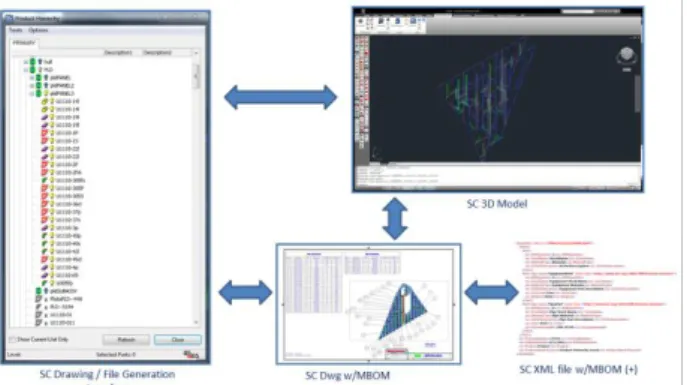
Figure 5 shows the XML file export conceptual diagram that required a command to be developed that would focus in on the export of an mBOM data set from a ShipConstructor drawing into the neutral XML schema defined within the targeted project work scope. Refinement was made to the SC Product Hierarchy software that is used to generate the output for SC Drawings with mBOM. The business process identified by the shipyards required that an XML file associated with a specific SC Drawings with mBOM be generated at the same time. This allows for a Product Work Breakdown Structure (PWBS) that serves as containment or grouping of the mBOM data that will be imported.
Figure 5 A Concept diagram of the XML file Export relationships
In order to test the data exchange, each participating shipyard provided a ShipConstructor project for testing purposes. The modified refinements were made to the ShipConstructor software that facilitated the generation of the XML file during the automatic generation of the SC Drawing file from the SC Product Hierarchy. The associated XML output document was documented by the XML Schema Definition (XSD). This XSD document provides all of the details required to write a valid XML document that can be parsed and processed by the methods used to insert this data into the ERP system, and most importantly; it is not specific to any particular software. SSI developed an application as a dynamic link library (DLL) for ShipConstructor that would expose a new command to export all of the required data to a neutral file format temporarily. Figure
ICCAS 2011, 20 - 22 September 2011, Trieste, Italy
© 2011: The Royal Institution of Naval Architects XML output file containing all of the required material data from a SC Product Hierarchy.
Figure 6: ShipConstructor ERP Export
SSI developed an application that would input this neutral XML file as generated with corresponding SC Drawing data as shown in Figure 7, parse the associated data, and then present that data to the end user for verification in any internet browser prior to import into the ERP system.
Figure 7: XML Sample Output
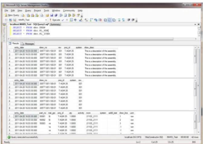
It is important to note that prior to an ERP XML import any extraneous data not created and managed by ShipConstructor, but still required by the ERP system could be manually filled out and modified. It was important that the XML Schema and File be capable of being extended so that when additional data requirements based on the business process are identified and determined to be required, the data will be available from within ShipConstructor. In the case of MARS ERP, this application would allow the user to push the parsed data out into a SQL table within MARS ERP as shown in Figure 8. This application shows the parsed data that will be fed into the MARS ERP where the business logic is pushed forward internally within MARS to the required locations and for the intended uses.
Figure 8: Material Data Imported Into MARS
Figure 9 shows the material data from the selected project using the MARS Importer utility which yields a successful import of the XML file into the MARS database. As noted, MARS ERP contains the business logic required from that point to push the data into the appropriate locations internally within its own database tables for further use.
Figure 9: MARS Import of XML Data
Each ERP system follows a similar configuration, but utilizes the same principles in maintaining the consistencies required in the importing of ShipConstructor XML output data.
4. CONCLUSIONS
At the start of this project work, each of the shipyards that SSI worked with had no ideal integrated method of data transfer from their selected design tool of choice (ShipConstructor) into their selected ERP system of choice. Manual methods of repurposing the data from one system to the other were common in the shipyards examined as part of this project. With no standard method of electronic data transfer, these processes allowed for a certain level of uncertainty or human error to creep into and corrupt further processing of data downstream. Each shipyard had actively searched for the
standard data exchange in a neutral format as the initial steps towards helping provide benefits in providing a data exchange solution.
Some of the lessons learned within the scope of this project initiative include:
Have all of the key shipyard process owners available to review the business process and agree on both the “As-Is” and “To-Be” processes defined. There will be data elements not revealed in the data
capturing process. Having a flexible means to update the XML Schema per these modifications or additions is important.
The order of the XSD document and the XML data elements when parsing the output data matters. With a working product in place, some of the benefits being shared from the shipyards are the following: Having documented “As-Is” business process
models defined by the key process stakeholders facilitates communication and allows for organized continuous improvement through a “To-Be” process modeling technique.
Time is saved and potential errors reduced by replacing a manual method of data entry associated with production documentation within engineering, material control, material procurement, material planning, and production departments.
The software integration allows for varying production method changes and seamless material information to be exchanged.
It provides a means for managing material information for procurement methods and decisions that could combat unavoidable manpower increases, schedule and facility impacts, and material requirements needed in specific areas for work-arounds.
It provides a means for cost avoidance associated with confusing redundancy within business process related work activities.
It yields a reduction in labor hours in material identification, procurement, planning, and warehousing.
It yields a reduction in labor hours associated with utilization of manpower in that accurate materials are provided when work tasks are scheduled. Production throughput is increased by improving the
ability to provide more JIT materials to the shop floor.
A reduction in schedule interruptions is being seen due to the ability to accurately see material planning needs that are based on the production drawing packages produced by Engineering.
which ShipConstructor Software Inc. can further explore deeper integration with ERP systems and other systems alike. As with this project, the key to success will be collaborative engagement with the shipyard community and an understanding of each shipyard’s business process and requirements.
5. AUTHORS’ BIOGRAPHIES
Darren Larkins holds the current position of CEO of ShipConstructor Software Inc. (SSI). He is responsible for SSI’s global operations and the overall direction and development of the company and its products. Mr. Larkins combines over 10 years experience in the development, marketing, sales and implementation of marine systems with the knowledge gained from onsite visits to shipbuilders and offshore experts in over 15 countries. Larkins played a lead role in the US National Shipbuilding Research Program (NSRP) - Second Tier Shipyard Design Enhancement Project (STSDEP) as well as recent NSRP projects focused on Design for Production (DFP). He has also presented papers on shipbuilding at various international conferences. Patrick Dean Roberts holds the current position of Director of Operations at ShipConstructor Software USA, Inc. He is in charge of al US-based sales, support, training, consulting, custom integration and development, and various research and development projects focused on the US market. In the past, Roberts has served a two year term as the Vice Chairman of Ship Production Process Technologies in the United States National Shipbuilding Research Program (NSRP) that is governed by 12 Executive Members of a consortium elected shipyard organization. Mr. Roberts is currently serving in his second two year term as the NSRP Vice Chairman of the Business Process Technologies Panel. He has ten years of US shipbuilding, repair, and retrofit experience in the areas of engineering, planning, project management, and research and development, as well as 4 years as an executive manager with ShipConstructor Software USA, Inc.