November 17 00 Sarjoun Samir Doumit
Masters
Computer Engineering
ActiveSPEC and ANSE usage environments in ORBIT
Dr. Perry Alexander Dr. Hal Carter Dr. Hongwei Xi
ActiveSPEC and ANSE usage environments
in Orbit
A thesis submitted to the
Division of Research and Advanced Studies
of the University of Cincinnati
in partial fulllment of the
requirements for the degree of
MASTER OF SCIENCE
in the Department of Electrical & Computer Engineering
and Computer Science
of the College of Engineering
2000
by
Sarjoun Samir Doumit
BS (Computer Science), Notre Dame University, Lebanon (1997)
Thesis Advisor and Committee Chair: Dr. Perry Alexander
This thesis proposes a CASE tool
A
CASE which is an integration of dierenttech-niques for the formal modeling and simulation of Active Networks. Active networks, proposed by DARPA, have revolutionized the traditional view of networks from a passive carrier of data into a more of a computational engine. Usage of formal meth-ods for the specication and verication of such systems oers a high level of modular abstraction and early design error detection. Simulations also aid in the examination of complicated network scenarios and help shape a better understanding on systems that would, otherwise, prove very dicult to analyze. However the implementation of formal methods is hard even for experienced users especially in complex appli-cations, thus, trends in rendering formal methods more transparent are presently emerging. This thesis oers a solution by oering a new and extensive tool that com-bines theActiveSPECformal specication framework and theANSEDsimulation
engine.
A
CASE is a high-level graphical user interface for the development (services,Acknowledgments
There are a lot of people I'd like to recognize during my work at the University of Cincinnati.
I must thank my advisor, Dr.Perry Alexander for his guidance, constant encourage-ment, enduring patience and faith in my abilities throughout the course of my gradu-ate studies. My thanks are also due to my thesis committee members,Dr. Hal Carter
and Dr. Hongwei Xi.
Not to leave out my lab-mates at the KBSE Lab. especially Darryl Dieckman,the
Ac-tiveSPEC guy, (has seen two guys graduate on his work) who oered me valuable
assistance whenever I asked for it.
I would also like to thank my father Samir, mother Hoda, brother Habib and
sis-terElissarfor their wonderful love and support for me, while I went through graduate
school.
My heart goes out to Johaina for supporting me and giving me the strength and a good laugh whenever I needed it most. Thank you habibti.
List of Figures
iii
1 Introduction
1
1.1 Motivation . . . 1 1.2 Problem Introduction . . . 2 1.3 Proposed Solution . . . 4 1.4 Contribution . . . 6 1.5 Thesis Organization . . . 72 Preliminaries
8
2.1 Active networks . . . 82.2 The ActiveSPEC framework . . . 10
2.2.1 The Packet Datatype Specication . . . 11
2.2.2 The Node Datatype Specication . . . 12
2.2.3 Abstraction Level . . . 15
2.2.4 Assumptions . . . 15
2.3 The ANSE Simulation Engine . . . 17
3 Gravity and Orbit
21
3.1 Introduction . . . 213.2 GRAVITY . . . 22
3.2.1 Introduction . . . 22 i
3.2.2 Overview of GRAVITY's concepts . . . 23
3.2.3 Description of GRAVITY's usage environment . . . 24
3.3 Orbit . . . 26
3.3.1 Introduction . . . 26
3.3.2 Overview of Orbit's concepts . . . 27
3.3.3 Description of Orbit's usage environment . . . 32
3.4 Conclusion . . . 34
4 ACASE 35 4.1 Introduction . . . 35
4.2 Preliminaries and description of the tool . . . 36
4.3 ACASE data structures . . . 43
4.3.1 Support for ActiveSPEC Modeling . . . 43
4.3.2 Support for ANSE Modeling . . . 54
4.4 Evaluation . . . 67
4.4.1 Ping Protocol . . . 67
4.4.2 Generic Network Simulation for ANSE . . . 72
4.4.3 Conclusion . . . 77
5 Literature Survey and Related Work 80 5.1 Introduction . . . 80
5.2 Active Networks . . . 81
5.3 Graphical formalism and simulation in active networks . . . 84
5.4 Active Network Simulation Environment . . . 87
6 Conclusions and Future Work 89 6.1 Achievements . . . 90
6.2 Future Work . . . 91
6.3 Thesis conclusion . . . 92
Bibliography 94
2.1 Active Packet Execution and State Transformation of the Active Node 16
2.2 ANSEd and ANSE general architecture layouts . . . 19
2.3 Taxonomy of dierent possible applications of Active networks . . . . 20
3.1 General view of the Gravity system . . . 24
3.2 General view of the Orbit system . . . 27
3.3 Orbit-Gravity Component Model . . . 28
3.4 The Representation's Types . . . 29
3.5 The Diagram Editor showing an Architecture for the Find component using a Sort and a Binary Search component . . . 31
3.6 Orbit Main Window . . . 34
4.1 View of the Activenet Diagram Editor . . . 37
4.2 Right-side view of the Palette in ACASE . . . 39
4.3 Left-side view of the Palette in ACASE . . . 40
4.4 The generic RepTypeHierarchy for ACASE in Orbit . . . 41
4.5 The Specication tree model in Orbit-Gravity . . . 44
4.6 The Specication is used to describe the Active Nodes'resources, ser-vices and policies . . . 45
4.7 The Resource Editor . . . 45
4.8 The Service Editor . . . 46
4.9 The Policy Editor . . . 48 iii
4.10 The Specication is used to describe the ActivePacket'spre-conditions,
post-conditions, payload and imports . . . 49
4.11 The Active Packet Editor . . . 50
4.12 The generic RepTypeHierarchy for ActiveSPEC in Orbit . . . 51
4.13 The Specication tree model in Orbit . . . 53
4.14 Adding active packets to the packet queue of an active node . . . 55
4.15 The Object Stub tree model in Orbit . . . 57
4.16 The Object Stub is used to describe the network's Object Denition, Object Instantiation and NetList sections . . . 58
4.17 Example of Network Topology for ANSE (TSL) . . . 59
4.18 TSL le for previous network . . . 61
4.19 View of the Common Functions to all TSL sections in ANSEd (ANSE Editor) . . . 63
4.20 View of the Object Denition Section . . . 64
4.21 View of the Object Instantiation Section . . . 65
4.22 View of the NetList Section . . . 65
4.23 The Object Stub tree model in Orbit . . . 66
4.24 The ActiveSPEC PING model showing 2 nodes local and remote . . . 68
4.25 The Payload is a simple structure that contains the payload type and value . . . 69
4.26 The Pre-Condition for the Ping Protocol . . . 70
4.27 The Post-Condition for the Ping Protocol . . . 71
4.28 The ANSEd generic network model showing the PING network model and Node C . . . 73
4.29 The generated TSL le . . . 74
4.30 The simulation result . . . 75
4.31 The small network used in ActiveSPEC and ANSE . . . 77
4.32 The large network used in ANSE . . . 78
Introduction
1.1 Motivation
The emergence of Active networks as a new paradigm in the networking world helps address to many problems faced with the present networks. Such problems include the diculty of integrating new technologies and standards into the shared network infrastructure, poor performance due to redundant operations at several protocol layers, and diculty accommodating new services in the existing architectural model [32]. The Active network is dierent from a traditional network in that it allows introduction and execution of programs into nodes or packets while the network is active. Active network packets dier from their counterparts in passive networks in that they are executable, while passive packets are constituted from blocks of data
that the network passively conveys from one end-point to another.
Active networks in their sophisticated form \have become customized infrastructures that let designers program control planes-the control software and network hardware used to manipulate the transport system's behavior" [18]. These issues help designers to address and solve the aforementioned problems. Extensive research in Active networks emerged with the advent of this exciting new technology, with aims to harness the multiple possibilities it has to oer. Yet very few researchers target its design and modeling. Note that due to lack for standardization and complexity in Active networks, specication of traditional networks is a much easier task.
The techniques that were integrated within theOrbitframework for the formal
spec-ication and simulation of Active Networks wereActiveSPECand ANSE, both
un-der development at the University of Cincinnati. TheActiveSPEC [12] framework
was designed for the formal specication and verication of active networks services and security policies. While the active network simulation engine ANSE was designed for the complete simulations of large scale active networks based on a parallel discrete event simulation environment [27].
1.2 Problem Introduction
Active networks oer a challenge in their specication and modeling due to their design complexity. This is because of the very nature of Active networks that allow
the dynamic reconguration and redeployment of protocols and nodes through its executable components. Many solutions, introduced by this complexity, have not been investigated thoroughly yet.
As such, the need has arisen for a comprehensive approach for the modeling and design of Active networks. Formal methods basics provide clarity and depth to the design process and ultimately lead to the correctness of the whole design. Simulations on the other hand oer powerful means for the exploration of complicated network scenarios that would be either dicult or impossible to analyze. Simulations also play an important role in helping researchers to develop presentative ideas on the realsystems [24].
One weakness in using formal methods for specifying systems lies in identifying the system's correct layout and parameters. By choosing any specication language, the user must be very careful to follow the semantics and strategies common to that language in addition to many other techniques in order to reach a concrete solution. Some existing systems (i.e. [22]) oer simulation of Active networks. However, al-most all these systems conne the usage of their systems to the restrictions of their specialized simulation language on the user. As networks grow large, constraints on the simulation environment due to its sheer size (i.e. simulation engine, limits on nodes in example) grow as well to become an obstacle for the simulation activity. Very few systems oer an automatic translation for large networks that is graphically
displayed into the specied simulation language with as little interaction by the user as possible. Our approach tends to be more general as it uses a common abstraction paradigm. A complex system, like active networks, may be composed of multiple, distributed components where subsystem dependencies between components are ex-plicitly required. In this case a good common abstraction is required to capture all their pertaining information and congurations.
1.3 Proposed Solution
Here, at the University of Cincinnati, two very signicant tools for the formal speci-cation and simulationof Activenetworks are being developed: theActiveSPEC
frame-work and the ANSE Simulation Engine.
TheActiveSPEC[12] framework was developed to support the formal specication
and verication of Active network components. This framework provides a common structure for Active network activities by specifying the architectures of an active \node" and \packet". It provides for the modeling of a programmable network al-lowing installation, use and removal of services, resources and security policies on the y [12].
The Active Networks Simulation Environment (ANSE [27]) is an environment for the design and analysis of large active network systems [27]. Simulation models for the three main elements of an active network (nodes, packets and topologies) have been
developed. [27]. The developers aimed to have as much general environment as they can, but their main aim was to build a WARPED simulation [27]. ANSE utilizes the TSL (Topology Specication Language) language.
This thesis presents
A
CASE: a graphical CASE toolset that integratesActiveSPEC[12]
and ANSE [27] into a single environment. By combining these two tools, this work aims to apply formal methods and simulation of Active networks in a common graphi-cal environment. Given an already developed formal specication framework and sim-ulation environment for Active networks,
A
CASE oers a graphic notation for theirmodeling and simulation to facilitate and rene the writing and understanding of specications.
A
CASE is a graphical environment intended to automate manual activities and toimprove engineering insight in the application of the Active networks. Models can be hierarchically structured, allowing their re-use in dierent systems. Specications are entered graphically with specialized editors. The editors provide an ecient medium for design capturing via a consistent set of modern user-interface elements.
This graphical Computer Aided Software Engineering - CASE editor is built using the Gravity [25]-Orbit [1] framework. Orbit [1] is an integrated environment built
on top of Gravity [25] for supporting component-based designs and analysis. Grav-ity [25] is a framework for the specication, design and analysis of components and architectures. The Gravity [25] framework allows designers to maintain collections of
components and various representations for those components. Hence the addition of
A
CASE, to this associated CAD (Orbit) environment, originally intended for
Hard-ware and SoftHard-ware specication and modeling, becomes a useful tool in building and simulating Active networks as well.
1.4 Contribution
This work is a collection of dierent techniques embedded in a common graphi-cal environment to ease the usage of formal methods. We automate the gener-ation of design specicgener-ations for vericgener-ation and simulgener-ation purposes. By using
the ActiveSPEC [12] framework in the proposed graphical editor, a designer can
easily model the various aspects of Active networking, apply mathematical analy-sis/verication techniques and simulate his/her design.
This thesis makes the following contributions in the application and deployment of formal methods and techniques, within theActiveSPEC[12] framework to support
the modeling of a Active networks
Provides a common abstraction for a CASE tool to deal with hardware/softare
design projects.
Provides the Active Networking community with a CASE tool for the
develop-ment and modeling of Active networks within theActiveSPEC[12] framework
through tool integration.
Provides a tool for the translation of a graphical network in
A
CASE into
TSL [29] (ANSE simulation language) and shows the results of its simulation
in ANSE [27].
Provides a tool which aids in the feasibility demonstration of using formal
meth-ods activities in the Active network design eort.
1.5 Thesis Organization
The remainder of this thesis is organized as follows: Chapter 2 describes the concepts relevant to this thesis and elaborates on Activenetwork theory; Chapter 3 explains the Gravity [25]-Orbit[1] framework and how the concepts t in its system; Chapter 4
provides an insight into our GUI editor for an Active Network modeling environment
forActiveSPEC[12] and simulationfor ANSE [27], descriptions of examples(PING)
PVS [23] le generation and of the simulation process is presented. Chapter 5 follows by a discussion of related work on Active network implementations application and deployment in addition to conclusion and future work in Chapter 6.
Chapter 2
Preliminaries
2.1 Active networks
In current networking environments, every network component should be registered in a certain protocol that allows it to communicate to all the present interfaces. The most famous of those is the IP: Internet Protocol. IP gives every station connected to the internet a unique IP address to make possible the forwarding and routing of data.
The prospects of upgrading the internet is a large task that might require years. Even some portions of the network might need to be switched o, in addition to that, some inconsistencies might develop, in the form of lost data. According to Tennenhouse [13], after a concept is prototyped in the networking eld, its large-scale
deployment takes about 8 years.
Active network technology is addressed to remedy this problem by decoupling the software related network services from their underlying hardware. In a similar fashion to the IP's enablement of a range of upper layer protocols, the Active network will facilitate the growth of novel network services and their hardware platforms [13]. The Active network technology will accelerate the pace of innovation [13], by representing a revolutionary approach to a networking architecture through the combination of its interposed computation.
Active networks can be grouped according to the functionality embedded into their programmable components. Theprogrammable nodeapproach (routers and switches): the user injects into the programmable node his customized programs intended for execution on the data owing through them. The data encapsulation approach is where the users can custom-program the network through integrating their codes into the Active packets of the network. Those packets, in their turn, would perform computations at the Active nodes. The Active nodes are tted to oer the execution environment required by the programs encapsulated in the Active packets carrying them.
With any emerging technology, it is hard to assess the extent of Active Network's benets from the beginning. Time and its application in target projects help estab-lish a much more correct evaluation. The selling point of Active networks seems to
emerge from its dynamic application of user-dened programs hence stressing on the acceleration of the pace of innovation [13].
Active networks introduce a dynamic environment that allows the modication and upgrading of old protocols in existing networks. This is a very basic and important characteristic vital for the renewal and maintenance of any network. This increased demand for the supplied services suggests that the current network architectures must adapt to deal with this new reality [32]. Active networks separate the interdepen-dence for the applied networking software from the underlying architecture layout. A brief taxonomy of some Active network applications is displayed at the end of the chapter.(gure 2.3)
2.2 The ActiveSPEC framework
The ActiveSPEC framework was presented by Dieckman [12] et al to support the
formal specication and verication of Active network components. A collection of PVS theories represent dierent ActiveNet elements that when combined together, form an active network specication. Those theories form the ActiveSPEC
frame-work that supports the concept of a programmable netframe-work by allowing services, resources, and security policies to be installed and removed dynamically. Active network components modeled within ActiveSPEC use the domain specic
param-eterization of this framework theories. Thus, the framework provides a standardized 10
approach for modeling of a variety of active network components and protocols.
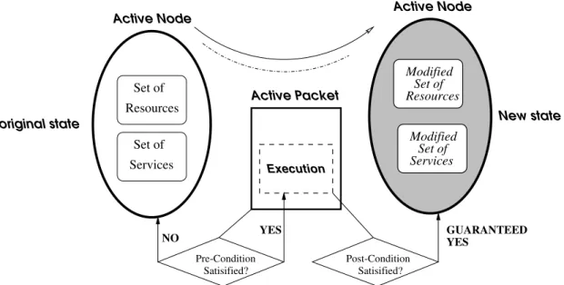
ActiveSPECuses a state transformation function to form the computational model
for the active network. The transformation of the modeled active network from one state to the other is determined by the process of packet manipulations. An important distinction between a traditional passive network's behavior to that of the Active
network (in ActiveSPEC [12]) is that it is packet-centric. The state transition
of the Active network is triggered by packets. For example, the resources that an active node holds before the arrival of a packet can be altered if that packet holds additional resources that can place restrictions on the original resources. The services provided by this node originally could as well be modied, i.e. a node server no deA, functioning as a gateway to another secure node server no deB, can be transformed
into a rewall for better protection if a security breach is suspected. Active nodes as well can run programs and routines on packets and are capable of sending packets and reply-packets when packets reach their intended destinations.
2.2.1 The Packet Datatype Specication
ActiveSPEC[12] axiomatically species the active packets by using a pre-condition
and a post-condition.
The pre-condition: outlines conditions that must hold in the active node prior
to the execution of the active packet. One common reason behind the packet 11
pre-condition is to check that the packet has access to services it requires. In PVS, a packet pre-condition is a function that takes a packet and a node and returns a boolean.
Pr e Condition:TYPE = [Packet;Node!bool]
The p ost-condition: of the packet is guaranteed to be satised after executing
the packet, if the pre-condition of the packet is true. The packet post-condition species the state of an active node after the execution of the packet. In PVS, a packet post-condition is a function that takes a packet and a node and returns a node.
Post Condition:TYPE = [Packet;Node!Node]
The general packet data type in PVS has the following form :
Packet : TYPE = [#
ptype : PacketType,
payload : Payload
#]
Where ptyp erepresents the actual packet's type and the payloadthe payload type its
carrying. Every packet in ActiveSPEC must have a dened payload. The policies
and restrictions that the packet's pre and post conditions enforce determine its type.
2.2.2 The Node Datatype Specication
An Activenode inActiveSPECis a programmable component that processes Active
packets. The modeling of an Active node resides in the specication of its underlying 12
elements. Using theActiveSPECframework, a user can formally specify an Active
node's services, resources, and security policies. The Active Node's state can be represented by the collection of its sets of basic components, i.e. a tuple<Resources, Services, Policies >.
The Active Node Resources: The Active node's resources represent the
phys-ical and information resources of that node. The resources can represent the actual memory, routing table or clock pertaining to that node. But resources cannot be accessed directly by the Active packets. The Active packets must utilize the set of available services in order to manipulate the resources. The resources in ActiveSPEC, must have a unique resource identier and data
type. A resource \record" is then dened from the sets of resource identiers and data types. The Active node theory then accesses its resource record as a parameter to customize it for its current specication. A set of the node's resource identiers is then maintained to determine at any time what resources are actually installed on the node. An example of resource identiers of a PING example is given below:
ResourceID : TYPE = f
routingTable, %% The routing table's type
pingSuccess, %% Boolean set to true if success
pingDied %% Boolean set to false if failure
g
The Active Node Services: The services represent the programmable
function-ality of an Active node that may manipulate the node's resources. In
Ac-tiveSPEC, the service is a function that takes a number of parameters and
returns an unconstrained type. Similarto resources, each service must be associ-ated with a unique identier. TheActiveSPECframework allows all nodes to
possess all the available services to the network. However, unless specied oth-erwise, the actual set of available services on a node is dened by that node's set of service identiers. An example of a generic node services is sending a packet or reading a secure resource:
sendPacketSVC(pkt : Packet, node : Node) : Node =
node WITH [(out) := add( pkt, out(node)) ]
readSecureSVC(node : Node) : SecureResource =
secureResource(data(node))
The Active Node Policies: The Active node in ActiveSPEC possesses a set
of security policies intended to restrict access and govern its services. Active networks are programmable elementsand hence specify suitable security policies to oer protection to valuable resources is critical. ActiveSPEC treats the
specication of policies similarlyto that of services. A set of identiers pertinent to policies identify each policy separately. The security policy is composed of two functions: The rst function is for a per-packet access restriction to services, the second function for a per-policy service governance. Note that the rst function is also called the Access Function, and in PVS, the policy is dened as
a function that takes a service ID, packet and a node and returns a boolean.
2.2.3 Abstraction Level
ActiveSPEC provides abstraction above that of actual code. This allows the
Ac-tiveSPEC specications to be written independently of the actual Active network
computing environments such as PLAN [15] or ANTS [33]. This fact adheres to the policy of not restricting models with any current approach in the Active network eld. Most Active network platforms allow active network services to be specied using a language that is proprietary to the computing platform. In such situations, Ac-tiveSPEC species the properties of these services independent of their
implemen-tation. This kind of abstraction proves to be useful at the modeling stage as it allows the designer to concentrate on whatthe service does, not how it does it.
2.2.4 Assumptions
The ActiveSPEC framework adopts some assumptions for its active network
mod-eling. These assumptions aect the possible verication activities. The current
Ac-tiveSPEC network model assumes that packet routing and delivery are part of the
basic functionality of the network. With respect to the types of packets that are available to the network at any time, an assumption is made that any packet may be selected for execution by the set of all available packets for transmission. This
assumption implies that the order of generated packets does not necessarily aect the order in which those packets are executed.
In ActiveSPEC, all verications are aected by two assumptions. The rst
as-sumption is an active node may execute only one packet at a given time. The second assumption is that packet execution is an atomic operation. These assumptions are a result of the packet specication model. The state of the node is only revealed after the execution of a packet, since packets are specied using a pre-condition and post-condition, and could not be checked at packet execution. Interleaving of packet execution could be a possible way for the simultaneous processing of packets by nodes to be done. But to interleave packets, more information is needed hence weakening our requirement of implementation-independent specications.
Set of Services Set of Resources Modified Set of Resources Modified Set of Services Active Node Active Node
original state New state
Satisified? Pre-Condition Satisified? Post-Condition Active Packet Execution
NO YES YESGUARANTEED
Figure 2.1: Active Packet Execution and State Transformation of the Active Node 16
2.3 The ANSE Simulation Engine
An important aspent in modeling complex networks involves the specication of the topology of the network, source of simulation modules and a number of parame-ters [10]. The topology and description of the network being modeled is presented to the framework in Topology Specication Language (TSL) format [10]. TSL is
designed to ease specication of large and complex networks. An other (ANSEd) editor translates the graphical network into TSL, and interfaces with the user for
the number of parameters needed. A simple methodology on translating the graph intoTSL is currently implemented. The translation is then fed to the ANSE
simula-tion engine and the simulasimula-tion results are displayed. The ANSE is composed of four sections (as mentioned in section 1.3)
Input Section : The input section provides the necessary input data needed for
the simulation. The main input needed for building the network's simulation is obtained from a conguration information (CI) stream [27]. This stream basically represents the data and parameters needed by ANSE for a complete simulation to occur. The conguration information should contain primarily the information about the le that contains the actual simulation object (with its associated parameters) and the topology of the network to be simulated [27].
Modeling Section : Because the technology is new and lacks standardization
especially in modeling, very few languages that model Active networks actually 17
exist. NetScript [31] is one of those language which routines were deployed in ANSE [27]. NetScript programs can be embedded into the network's elements. The network models that were developed using NetScript can be transformed to meet with the corresponding implementations as needed by the simulation engine [27]. The transmogrier could also generate the most atomic compo-nent/object of the whole specication model : the Object Stub [27]. The object stub constitutes the most atomic entity/component in the whole simulation en-vironment. The collection of object stubs constitutes objectfactories and sub-factories. Basically it is the factories that generate the multitude of the object stubs, based on the parameters entered by the user. The factories play a major role in furnishing a homogeneous interface for the maintenance and subsistence of the simulation.
Assembly Section : This section is made up of the collection of factories in
addition to the Simulation manager. The assembly section analyzes and taxon-omizes the associated factories. This is done in order to extract all the required objects and lter the necessary information needed, then all the data is assem-bled in order to set up the simulation.
Simulation Section : The simulation section denes the actual simulation's
en-gine and comprises many other sub-sections. The main parts are the WARPED Time Warp simulation kernel. The ANSE framework is built around WARPED,
which is a parallel optimistic simulator [29]. WARPED uses the Time Warp [17] paradigm to achieve distributed synchronization. A Time Warp synchronized simulation is systemized as a set of asynchronous logical processes (LPs) that describe the dierent physical processes being modeled [29]. The LPs commu-nicate between each other by exchanging virtually time stamped events [27].
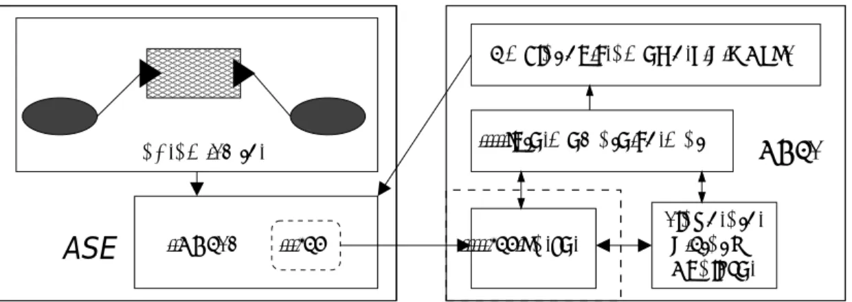
A
CASE 00000 00000 00000 00000 00000 00000 00000 11111 11111 11111 11111 11111 11111 11111 Diagram Editor TSL ANSEdSimulation Framework & WARPED
Intermediate Format TSL Parser Analyzer & Static Elaborator ANSE
Figure 2.2: ANSEd and ANSE general architecture layouts
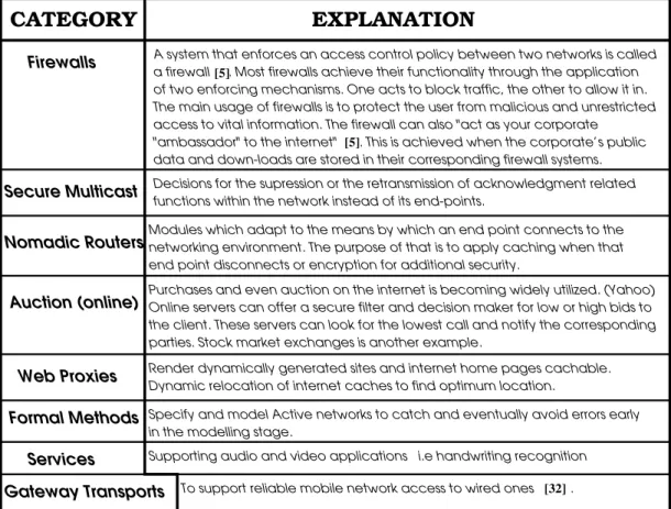
CATEGORY EXPLANATION
Firewalls A system that enforces an access control policy between two networks is called
of two enforcing mechanisms. One acts to block traffic, the other to allow it in. The main usage of firewalls is to protect the user from malicious and unrestricted access to vital information. The firewall can also "act as your corporate
data and down-loads are stored in their corresponding firewall systems.
Secure Multicast Decisions for the supression or the retransmission of acknowledgment related Nomadic RoutersModules which adapt to the means by which an end point connects to the networking environment. The purpose of that is to apply caching when that
end point disconnects or encryption for additional security.
Auction (online) Purchases and even auction on the internet is becoming widely utilized. (Yahoo)Online servers can offer a secure filter and decision maker for low or high bids to parties. Stock market exchanges is another example.
Web Proxies Render dynamically generated sites and internet home pages cachable.
Dynamic relocation of internet caches to find optimum location.
Formal Methods
in the modelling stage.
Services
Gateway Transports
[5]
a firewall . Most firewalls achieve their functionality through the application
To support reliable mobile network access to wired ones . [32]
Supporting audio and video applications i.e handwriting recognition
"ambassador" to the internet" . This is achieved when the corporate’s public [5]
functions within the network instead of its end-points.
the client. These servers can look for the lowest call and notify the corresponding
Specify and model Active networks to catch and eventually avoid errors early
Figure 2.3: Taxonomy of dierent possible applications of Active networks
Gravity and Orbit
3.1 Introduction
The design of large-scale system is a complex process that involves the use of dierent tools that operate on dierent aspects of the design. In addition, there are several tools available to designers to aid in verifying the correctness of designs. For exam-ple, simulation is used to quantify the performance of designs and to detect many design errors. Similarly, formal methods are used to establish correctness properties of the system or its subcomponents. That's why the need for a system to integrate all these tools is imperative for solid design activity. That's why,the KBSE Lab, at the University of Cincinnati, has developed Gravity [25], a tool integration framework
intended to support a design activity with its set of required tools.Gravitywas built
intentionally without any front end, hence leaving it for the tool builder to customize
his/her own.Orbit: an environmentfor the integrated hierarchical design and
analy-sis, was built on top of Gravity. TheOrbitenvironment is a front end toGravity's
set of core classes.Orbit utilizesGravity for its support of hierarchical design and
acts as an API (Application Programming Interface) for the integration of tools into the environment [1].
3.2 GRAVITY
3.2.1 Introduction
Gravity is intended for building domain-specic design environments [25]. Gra v-ity utilizes a set of objects to represent the various parts involved in a design, and
then associates a set of tools with them. As mentioned in the introduction, theGra v-itysystem is constituted from a set of core classes written in JAVA[14]. Those classes
can be customized to suit the user's needs.Gravityrequires that the design activity
being conducted to be modular [25], coinciding with today's design trends as well. Some aspects of Gravity include:
its ease to be extended by the tool builder [25] for sound software engineering
practice.
its independence of the storage mechanism [25]. This is intended so that the
tool-builder will have his choice in choosing the best/most suited storage envi-ronment for his application.
its portability across dierent platforms and operating systems [25].
3.2.2 Overview of GRAVITY's concepts
Tool builders build design environments using Gravitywith the support of its tool
integrating framework. In order for the tool builder to utilize Gravity, he/she
needs to supply its application with a front-end (such as a Graphical User Interface (GUI)) [25]. Gravity requires this from its intended users simply because many
dierent types of designs exist. The elegance of Gravity's design lies in its
indier-ence between hardware and software modules, thereby facilitating software/hardware co-design. Gravity uses a set of design objects:
The component: The component paradigm encapsulates the most basic design
object. The component has a multitude of facets corresponding to dierent aspects of the overall system's functionality.
The ports: As their name suggests,portsserve as input and output gateways to
the components, connecting other components together.
The connections:connections simply represent the link found between the ports
of corresponding components or their facets. 23
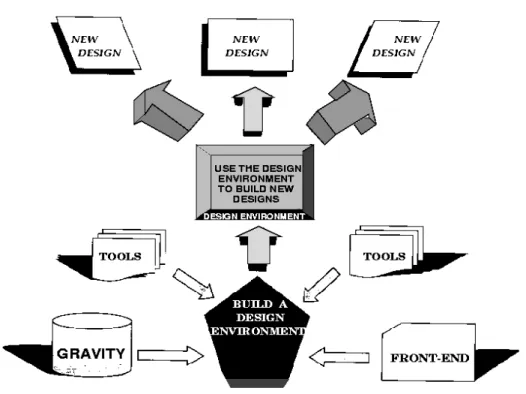
Figure 3.1: General view of the Gravity system
3.2.3 Description of GRAVITY's usage environment
The design objects mentioned in the previous section (component, ports and
connec-tions), are all subclasses of Gravity's own design-object[25]. Each design-objecthas
its corresponding use class that contains information specic to an instance of the corresponding design object [25]. The set of design-object together with their corre-sponding use classes represent a model of the class-instance relationship.
InGravityeverycomponentcan have one or more associated representations. A
resentationis any information pertaining the component, such as behavioral specica-tion, source code representation or even a composite picture representing the object or its sub-components[25]. For eachrepresentationinGravityan associatedlanguage
should exist that determines the format and type of this representation, i.e. (i) for a visual description language, its corresponding representation is a graphical form; (ii) for a hardware descriptionlanguage, its representationis in a form of a block of code in a textual format.
AlanguageinGravitycorresponds to a system suitable for the expression of certain
concepts including a set of objects and rules for their manipulation. Every language
has at least one corresponding tool. The tools inGravity express the actions that
can be taken on therepresentationof every component [25]. To ease use in the design process, the concept of a library is introduced as a set of relatedcomponentsgrouped together. The use of libraries encapsulates components of a certain design, hence a user can easily see the building parts of a certain design at one glance. The library therefore becomes a sort of meta project. Importing components across libraries is feasible but could result in inconsistencies. The problems that might occur has to do with nomenclature. Libraries forbid components within one library to share names. Other problems that might arise are of design issues. Somecomponents are made up from smaller sub-components. The modication or deletion of one disposable
compo-nent in one design, can create inconsistencies in another design that relies on that specic component.
3.3.1 Introduction
The process of designing highly complex systems relies on the ecient utilization of multiple tools. Tools vary with the aspect of the design that the user is currently interested in. The approaches used to verify the correctness of the design also dier for the dierent existing domains. Verication of the correctness of the design is a very important in the design cycle; therefore there is considerable interest in the use of the dierent approaches and tools in a complementary manner to provide a higher degree of assurance. But because of the dierent existing model constraints, design incompatibilities emerge amongst the various tools; hence heterogeneous design and analysis is very hard. The Orbit [1] system was designed to address this problem.
Orbit is a heterogeneous, component-based design and analysis environment. The
dierent segments are:
The Gravitycore classes. Orbit by denition is built on Gravityand uses
its classes.
The GUI front-end. It allows the users to construct their designs, use tools and
analyze their results.
A set of programming tools (compilers, editors...). These are tools specic to
the design domain that the environment is being built for. 26
A JDBC database for storage purposes. a database for storing the libraries of
components.Orbit utilizes a JDBC compliant database that can be used with
any JDBC compliant database [1].
Figure 3.2: General view of the Orbit system
3.3.2 Overview of Orbit's concepts
Orbit oers an environment/framework for the building of hierarchical designs and
analysis. Orbit revolves around the concept of component-based design models. In
order to handle the complexity of the system, top-level components are broken down into smaller sub-components. These sub-components could be interconnected to-gether, hence forming the overlaying parent-component. This approach displays in-tuitiveness in the design cycle that allows for complex component decomposition. Originally all applications forOrbitwere geared towards hardware description,
cation and constraints evaluation. Hence the system for design analysis relies on
con-gurations and architectures.
Orbit relies on an importantGravity concept which is the component. The
com-ponent is viewed as a \black-box", with a specic interface (described as input and
output ports) [1]. The component has three types of descriptions associated with it 3.3:
COMPONENT
ARCHITECTURES
REPRESENTATIONS
CONFIGURATIONS
Figure 3.3: Orbit-Gravity Component Model
The representation: The representation paradigm is an atomic description of
the component. The representation is a description or illustration of that black
box (or component) in a certain language; hence the namerepresentation. The
representation contains all the data and features that a component needs to possess, to be in that language. For example: a VSPEC [3, 2] representation is a collection of eight textual clauses. VSPEC being a requirements specica-tion language for digital systems, its representaspecica-tion contains the requirements,
constraints clauses (amongst other clauses) for that component. Together they represent a complete physical lerepresenting thatcomponentin VSPEC. Rep-resentations can also play a larger role in non-hardware design systems. As men-tioned earlier,Orbit is geared towards hardware dominated systems hence all
the constraints of building hardware components are considered and managed. The VSPEC and VHDL languages are the predominant hardware-description languages utilized. These languages rely on an iterative description of systems where the systemcomponentscan be successivelyexplodedinto their underlying
sub-components, until theatomic componentsare reached.
REPRESENTATION
Atomic Component
Composite Component
ATOMIC REPRESENTATION COMPOSITE REPRESENTATION
Figure 3.4: The Representation's Types
In Orbit we have atomic and composite representations for corresponding
atomic or composite components. An atomic representation is a single insev-erable object such as the source code for a module or a packet for a network. A composite representation is made up of other components. For example, a component could be implemented as an interaction among a number of simpler
components. The architecture plays a crucial role in dening the nature of the
hardware component. But not all systems need that information to describe
their components. Therefore the only place where these systems can describe their designs and perform analysis is by using the representation paradigm.
The architecture: As the name suggests, architecturesare the structural
descrip-tions of components. An architecture is a structural portrayal of the component that is described in term of other components. Architectures also play an im-portant role for networking systems. For example, in a networking language, anOrbitcomponent could have a node representation, a packet representation
or combinations of both. Architectures can link those representations together forming whole networks on which analysis can be performed. For other lan-guages a component could be the composition of other two components (see gure 3.5).
Architecturesare edited inOrbitusing a graphical block diagram and represent
a facet that enables hierarchical design for the component. The graphical block diagram uses the Graph Editing Framework (GEF) v0.6 from the University of California, Irvine. GEF is a multi-purpose graph editing framework that oers many features that are useful to Orbit. Those features include a full editing
of unstructured graphs, multiple and coordinated views of complex graphs and ease of use. The GEF architecture is similar to that of Gravity in that GEF
also uses a 2-level approach to graph elements - the net level and the diagram 30
Figure 3.5: The Diagram Editor showing an Architecture for the Find component using a Sort and a Binary Search component
level. The net level is composed of the logical objects that make up the graph. These objects may have application-specic data and behavior, whereas the diagram level has structures and unstructured graphical objects that constitute the graphics of the diagram.
The conguration: Congurations are used to describe a specic design for a
component. More precisely, since each component is allowed to have multiple architectures andrepresentations, a conguration associates a unique represen-tation or architecture with every (sub)component that is used in the hierarchical description [1]. The need for congurations is necessitated because each compo-nent has representations from multiple languages, and multiple representations
for the same language. When the user needs to analyze a project, the analysis of the design needs to be done with respect to one particular representation for each component. Thus, a conguration associates a unique representation or architecture with every component that is used in the hierarchical design. For-mally, a conguration is a hierarchical tree description of the components such that every leaf of the description is an atomic representation and every inter-nal node is a composite representation (architecture). Each architecture node has an outgoing link for each of the components used in it. Since every leaf is a self-contained representation, congurations also represent self-contained descriptions of the component. Certain default congurations can be automat-ically generated in Orbit.
3.3.3 Description of Orbit's usage environment
In Orbit, tool integration and analysis are intended for creation of heterogeneous
evaluation of the systems under design [1]. Analysis in this context is a misnomer: Analysis in Orbit refer to the activities applied to designs. Those activities include
synthesis, editing or publishing. While the design model is used by the environment users, the tool integration and analysis models are of interest to the environment de-velopers. Tools can be integrated into theOrbitenvironment very easily.Orbithas
a toolBox menu that the user can use to add a tool (editor, compiler, translator..) which could be associated to a language.
At the conceptual level, Orbit supports hierarchical design. But in the actual
de-sign process, dede-signers do not use a strictly top-down or bottom-up dede-sign strategy. Therefore, Orbit permits the user to create components whose interfaces are alone
known and to use them in designs. Thus, when a component is expanded and assigned an architectural implementation, the process constitutes top-down design. When an architecture is reduced to obtain the interfaces of a new component, the process constitutes bottom-up design.
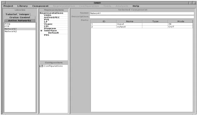
The user can create, edit and delete components in Orbit. At the time of the
component's creation, the user must enter its(component) name, while data related to its description and its ports is optional - depending on the type of application. Once the component has been created, information about the component can be added in the form of new representations. The user can select to add one of the following types of representations: VHDL, PVS, LSL, VSPEC, Diagram, and Ac-tiveSPEC. Editing these representations would bring up an editor. In the case of
the rst three representations, emacs is used as an editor. For VSPEC , a
cus-tom built editor \VspecEditor" is invoked. While for ActiveSPEC,
A
CASE is
sum-moned.
A
CASE represents the theme of this thesis.Figure 3.6: Orbit Main Window
3.4 Conclusion
The Orbit-Gravity system allows the design and analysis of systems by
allow-ing heterogeneous tool integration. Although designed for hardware dominated sys-tems [26], the tool's basic design-building-blocks usages were modied to t a formal active network activity. In Orbit acomponent is described by one or more
represen-tations.Componentsrepresent the most generic building block in Orbit. It is viewed
as a \black box" with a specied interface that is represented by a set of input and output ports [1]. The intended implementation of componentsinOrbit stressed the
usage instances of those components and their ports in hardware system building. 34
ACASE
4.1 Introduction
The objective of
A
CASE is to provide the user with the ability to combineheteroge-neous analyses techniques for the development of active networks. Active networks are complexsystems and no tool for the modeling of such networks exists to this point.
BothActiveSPECand ANSE are solution components for the aforementioned
prob-lem. Given an already developed formal specication framework for active networks, we develop an alternative graphic notation for its specication to improve writing and understanding of such specications. We also include a comprehensive simulation ed-itor for TSL, a topology specication language for the Active Network Simulation Engine (ANSE). The result is
A
CASE.4.2 Preliminaries and description of the tool
As with any Orbit design activity, starting with a component, a user's goal can be
to specify an active network and/or choose to simulate that network using ANSE. Then again, from within Orbit, the user would need to add a representation for
the ActiveSPEClanguage that
A
CASE would edit.
A
CASE makes use of a GEF(ref. 3.3.2) diagram editor that is a generic graph editingframework, in addition to a control palette for managing the network-representation. The diagram editor has been modied to describe network components. The dia-gram editor can be used to create Active Nodes or Active Packets. It is important to remember that the ActiveSPEC language in Orbit can be used to specify and
simulate an active network. The representation for that language has a common mod-eling abstraction that is the genericnetwork. Thisnetwork represents the domain for the specication and simulation alike where all the available components. In other words, the user can create multiple nodes from the diagram editor and those nodes would represent the multiple node-representation for that component. These nodes are dierent entities and signify multiple representations or models of the component in that particular language;
The user can \create" a node or a packet from the diagram editor, where it is added to the component and displayed in the palette. Then from within the palette, the user may chose what node, packet (or network) he/she would like to add to the original
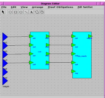
For adding Nodes
For adding Packets
network topology
Translates network into ActiveSpec specification and calls proover
Translates network into TSL specification and calls ANSEd to edit result
Canvas on which Nodes and Networks are added
Generic Menu
Describes current
Figure 4.1: View of the Activenet Diagram Editor
network representation. An advantage of such a design is to oer exibility in the de-sign process. A user can create a node (or packet) specication that he/she chooses to add later in the design process, or that is incomplete. Another important advantage is that the palette oers a view of the whole universe as well as the current representa-tion. The right side of the palette displays all currentActiveSPECrepresentations
for existing components. The user can import previously specied components and add them to the current representation. Once the node is added to the network rep-resentation, that same node appears in the node queue of that representation and a graphical object representing a node is made available for the user to paste on the diagram editor. The packet is addeddiscretely, in the sense that there is no graphical object referring to a packet. Only the packet's name is added to thepacket \queue"
of that representation.ACASEalso can import whole networks (similarly to nodes).
Note that once a network representation has been specied and saved, the whole network can be later on imported onto the network \queue" of that same network representation.
A
CASEuses another important feature fromtheOrbit-Gravityenvironment: the
rep-TypeHierarchy class model. This structure is used for storing the hierarchy of
repre-sentation types (orlanguages) in addition for its storage in the JDBC Data Base. This
class provides mechanisms to extend the type tree and to provide soft type checking. This fact proves extremely useful for a networking language where the representa-tion has 3 facets: (1)sub-networks, (2)nodes and (3)packets, that together form the generic network-representation.
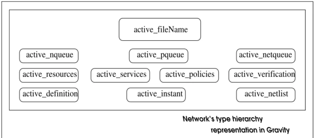
Figure 4.12 shows the representation hierarchies. The upper-most rectangle shows the main network section that is composed from:
active leName : As with most Orbit representations this representation has
a le where the representation is stored in a textual form. This is true of all textual language representations like PVS, ActiveSPEC and VHDL. This
contains the address of the physical le where the ActiveSPEC specication
is stored at.
active nqueue : Represents a queue or vector of objects representing all the
nodes that belong to the network. Note that when the user adds a node from 38
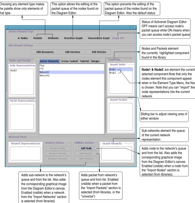
corresponding graphical image Adds node to the network’s queue and from the list. Also adds the representation
Status of Activenet Diagram Editor OFF means can’t access node’s
Nodes and Packets element found in the library
packet queue while ON means when you can access node’s packet queue
the currently highlighted component
Node1 & Node2 are element the currently selected component.Note that only the nodes element this component appeat when in the Element Type Menu, the Node is chosen. Note that you can "import" these node representations into the current network.
Choosing any element type makes the palette show only elements of that type
This option allows the editing of the packet queue of the nodes found on the Diagram Editor.
This option prevents the editing of the packet queue of the nodes found on the Diagram Editor. Also the default status
Adds sub-network to the network’s queue and from the list. Also adds the corresponding graphical image
Adds packet from network’s
from the Diagram Editor’s canvas.
queue and from list. Enabled (visible) when a packet from the "Import Packets" section is selected (from libraries, or the "universe")
Enabled (visible) when a network from the "Import Networks" section is selected (from libraries)
from the Diagram Editor’s canvas. Enabled (visible) when a node from the "Import Nodes" section is selected (from libraries). Sub-networks element the queue of the current network
Sliding bar to adjust viewing area of either window
Figure4.2: Right-sideview of the Palette in ACASE
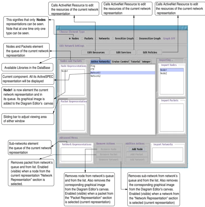
Sub-networks element representation
the queue of the current network Current component. All its ActiveSPEC representation will be displayed
Removes packet from network’s added to the Diagram Editor’s its queue. Its graphical image is network representation and in
Node1 is now element the current Available Libraries in the DataBase
canvas This signifies that only Nodes
the resources of the current network representation
Calls ActiveNet Resource to edit
representations can be seen.
Nodes and Packets element the queue of the current network representation
type can be seen.
Calls ActiveNet Resource to edit the resources of the current network representation
Calls ActiveNet Resource to edit the resources of the current network
representation
Note that at one time only one
Sliding bar to adjust viewing area of either window
queue and from list. Enabled (visible) when a node from the current representation "Network selected.
Removes sub-network from network’s queue and from the list. Also removes
the corresponding graphical image Removes node from network’s queue
and from the list. Also removes the corresponding graphical image from the Diagram Editor’s canvas. Enabled (visible) when a packet from the "Packet Representation" section is selected (current representation) Representation" section is
from the Diagram Editor’s canvas.
is selected (current representation) Enabled (visible) when a network from the "Network Representation" section
Figure4.3: Left-side view of the Palettein ACASE
Network’s type hierarchy
active_pqueue active_instant active_policies active_netlist active_netqueue active_verification active_fileName active_nqueue active_resources active_definition active_services representation in Gravity
Figure 4.4: The generic RepTypeHierarchy for ACASE in Orbit
the right-side of the palette representing the universe of objects to the left-side of the palette the objects proprietary to the current representation, she/he would be actually adding to this construct.
active p queue : Represents a queue or vector of packets that belong to the
network we're working on.
active netqueue : Represents a queue of sub-networks that are members of the
network. Logically, a network could be composed of nodes, packets or even networks that in turn can be composed of nodes, packets and other sub-networks. This construct has been applied in ANSE, but not in the current version of the ActiveSPEC framework. Of course each network's structure
follows the same hierarchy as described here. 41
Regarding gure 4.12 , the second line of objects (within the rst rectangle) is related to the ActiveSPEC framework's storage mechanism and organization :
activeresources: The list of resources available to the network. Resources is the
rst of the three requirements for a specication in the ActiveSPEC
frame-work.
active services : The list of services available to the network. Services are a
requirement for a specication in the ActiveSPEC framework.
active p olicies : The list of policies available to the network. Policies are a
requirement for a specication in the ActiveSPEC framework.
activeverication: The code entered by the user for the verication or
theorem-proving part.
The third line of objects (within the rst rectangle) is the part related to the ANSE's storage mechanism and organization :
active denition : The denition section in ANSE for the specication in TSL
active instant : The instantiation section in ANSE for the specication in TSL active netlist : The netlist section in ANSE for the specication in TSL
4.3.1 Support for ActiveSPEC Modeling
ActiveSPEC, one of the incorporated techniques, is simply a formal framework for
the specication of active networks. We had to encapsulate its data, keeping in mind the necessity for proper specication generation. A proper specication formalism is not enough for having a formal specication geared for real applications by non-specialized or well trained software engineers. The formal activity should be assisted by the following:
1. A methodology, that the user can safely follow a structure that would ultimately lead to a \robust" and \correct" formalism.
2. Supporting software tools that aid the user in following the methodology, by applying GUI's and user-friendly data models for the user interaction.
A new construct: specication, was added to aid in the modeling process. The
spec-ication is represented by a class that contains all necessary data required by
Ac-tiveSPEC. Thespecicationinherits from therepresentationclass for thelanguage
Ac-tiveSPEC. The representation is some model of the component and specication
adds the additional required data for the specication formalism. Also for the persis-tence storage issue, any object that needs to be saved from within theOrbit-Gra v-ity has to inherit from representation and be linked indirectly to thecomponent.
COMPONENT REPRESENTATION
SPECIFICATION
Some model of COMPONENT
inherits from REPRESENTATION
"Black Box" For the Active SPEC Language
LANGUAGE
Figure 4.5: The Specication tree model in Orbit-Gravity
Thesp ecicationcontains elds and pointers to other data models for the storage and
manipulation of the dierent parameters required. The specication was utilized to specify both active nodes as well as active packets.
4.3.1.1 Specication used for Active Node
TheActivenetEditor, a customizableeditor, is used for editing the sp ecications.Sp ec-icationsas mentionedearlier are used to describeActiveSPECconstructs.
Depend-ing on a certain variable, passed from the specication the ActivenetEditor would display the corresponding data values required for the data construct in question. Following is some explanation regarding someActiveSPEC constructs:
Resources represent the physical resources of the node (see gure 4.7). In
SPECIFICATION
Resources Editor Services Editor Policies Editor Argument Type Argument Name Body of service Theory Return Value Theory Return Value Identifier Type
( Identifier ) ( Identifier ) ( Identifier )
Govern Function Access Function NODE
( R E P R E S E N T A T I O N )
Figure4.6: The Sp ecicationisused to describ e the ActiveNo des'resources, services and p olicies
Resource Identifier Menu Specification Parameters
Figure4.7: The Resource Editor
Service Identifier Menu Specification Parameters
Figure 4.8: The Service Editor
tiveSPEC they are taxonomized as such:
1. Identier name of the resource, also known as the resource Identier.
2. Identier typ e (PVS)type this resource is member of.
3. Return value return value for all resources as they all should have a return
value, that is consistent with their types.
4. Theory theory(code) that must be imported to dene the type. The user
is responsible for making sure that all his types are well founded.
Services represent the programmable functionality of an active node. (see
g-ure 4.8). In ActiveSPEC they are:
1. Identier service's name, used to identify what type of service is provided
2. Return value return value's type must be determined.
3. Theory required code that must be imported. It is the user's responsibility
to know which theory he/she is importing.
4. Body of service PVS code that the user needs to input so as to dene the
body of the service and its functionality.
5. Argument name argument's name. The name is needed to identify the
service function.
6. Argument type is necessary to dene. This enhances the robustness of the
formal specication code. It described the argument taken by this service function.
Policies restrict access to active node services, and also govern the ability of
other policies to restrict access to services. (see gure 4.9).
1. Identier the policy name. The policy needs an identier to be identied
with.
2. Access Function this is reserved for the user to enter (PVS code) to dene
the body of the access function.
3. Govern Function again the user needs to enter (PVS code) in this
ed-itor for the govern function. These functions are needed by the Ac-tiveSPECconstructs for control and access of the construct (check [12])
The current version of theActiveSPECframework, all active nodes are all instances
adjust viewing Slide bar to windows
Menu
Policy Identifier Specification Parameters
Figure 4.9: The Policy Editor
of one generic node type. According to Dieckman [12], the current version of Ac-tiveSPECallows all node instances to have access to all resources,services and
poli-cies, that are available to the network as a whole.
4.3.1.2 Active Packet Specication
As with active nodes, active packets in the ActiveSPEC framework also utilize
thespecicationconstruct. Each active packet inActiveSPECdescribes a new type
by itself, while active nodes are all instances of the same node type.ActiveSPEC
de-nes the following constructs for the specication of an active packet: Pre-Conditions,
Post-Conditions, Payload and Imports. Each construct is made up of a specication
for the respectivecode and comment clauses. The active packet datatype is a simple 48
PACKET Pre-Conditions Post-Conditions Payload Imports S P E C I F I C A T I O N comments code ( REPRESENTATION )
Figure 4.10: The Specication is used to describe the Active Packet's pre-conditions, post-conditions, payload and imports
structure that contains the packet type and the packet payload record.
1. Pre-Conditionsspecify the conditions that must be present in the active node to
allow the packet to execute.
2. Post-Conditions specify the state of an active node after execution of a packet.
3. Payload specication of an active packet payload.contains an instance of every
possible type of payload.
4. Imports the user should enter the location of whatever additional or specic
dataypes needed for the specication. The original author ofActiveSPECwanted
Imports to act as a sort of a pointer to the needed data types.
The Active Packet Editor holds all the ActiveSPEC constructs for active packets
The four sub-specifications in ActiveSPEC
required by all packet types Menu
Code should go in here
User comments should go in here
Slide bar to adjust viewing windows
Figure 4.11: The Active Packet Editor
(Fig. 4.11). The user can enter all the required information in the corresponding windows: code for the actual specication in the Theories and Axioms window, and comments in the Comments window. Note that the user can also edit this data from withinOrbit. When the user rst adds a packet representation (from the
Activenet-DiagramEditor), the packet's name is added to the component's set of representations for the ActiveSPEC in Orbit. The user can then edit this packet representation
from within Orbit.
In the RepTypeHierarchy model, the ActiveSPEC framework elements t in the
whole scheme. Figure 4.12 shows an addition in the previous gure depicting the
generic repTypeHierarchyto encompass the active node and packetof theActiveSPEC
frame-work.
comment active_fileName active_pqueue active_instant active_policies active_netlist active_netqueue active_verification active_services active_definition pqueue active_resources active_nqueue representation in Gravity Packet’s type hierarchy
representation in Gravity
p_specs code
specs
Node’s instance hierarchy Network’s type hierarchy
p_fileName fileName p_code p_comment representation in Gravity
Figure 4.12: The generic RepTypeHierarchy for ActiveSPEC in Orbit
Node Representation : The node representation is created from the
Activenet-DiagramEditor and has the following elements:
{ leNameA pointer to a physical le for the user to save his/her
representation-specication.
{ code The collection of all code related to the node specication.
{ comment A comments section for the user.
{ specs The vector of all specications pertaining to the node.
{ pqueue The queue of all packets native to this node.
Packet Representation :
{ leNameA pointer to a physical le for the user to save his/her