04 August 2020
POLITECNICO DI TORINO
Repository ISTITUZIONALE
Evaluations on adequacy and utility of Failure Modes and Effects and Criticality Analysis and Fault Tree Analysis methodologies applied to civil RPAS systems / Bonfante, Federica; Dalla Vedova, Matteo D. L.; Maggiore, Paolo. - In: MATEC WEB OF CONFERENCES. - ISSN 2261-236X. - ELETTRONICO. - 233(2018).
Original
Evaluations on adequacy and utility of Failure Modes and Effects and Criticality Analysis and Fault Tree
Analysis methodologies applied to civil RPAS systems
Publisher: Published DOI:10.1051/matecconf/201823300002 Terms of use: openAccess Publisher copyright
(Article begins on next page)
This article is made available under terms and conditions as specified in the corresponding bibliographic description in the repository
Availability:
This version is available at: 11583/2718502 since: 2018-11-24T23:48:11Z
Evaluations on adequacy and utility of Failure
Modes and Effects and Criticality Analysis and
Fault Tree Analysis methodologies applied to
civil RPAS systems
Federica Bonfante1 ,Matteo D. L. Dalla Vedova1,*, and Paolo Maggiore1
1Politecnico di Torino, Department of Mechanical and Aerospace Engineering, Corso Duca degli Abruzzi no. 24, 10129, Turin, Italy
Abstract. This paper is on the Failure Modes and Effects and Criticality Analysis and Fault Tree Analysis methodologies applied to the equipment and functional subsystems of Remotely Piloted Aircraft Systems (RPAS). Such aerial vehicles have been used almost exclusively for military purposes until the first decade of the 2000s. The debate then was focused both on technical and regulatory issues and research activities. Thanks to this renewed interest on unmanned systems and thanks to relatively recent improvements in information science, telecommunication, electronics and material science a strong awareness on the potential extension of unmanned technologies to civil applications arose up. A variety of economic benefits has been recognized by the aviation community from the civil use of RPAS, but, due to the absence of the pilot on board both military and civilian RPAS have always been relegated to fly into segregated airspaces. Technical potentialities of RPAS will be fully exploited integrating them into controlled airspaces in a reliable and safe way. This paper shows an example of application of FMECA and FTA to RPAS and discuss the most critical issues related to the performed analyses as well as possible future developments of this work.
1 Remotely Piloted Aircraft Systems (RPAS)
Since the first decade of 2000s a new interest arose on civil Remotely Piloted Aircraft Systems (RPAS). The possibility to fly aircraft without the pilot onboard goes back to the years of the Second World War and in 1944 the International Civil Aviation Organization (ICAO) officially acknowledged the existence of unmanned aircraft in the Chicago Convention. The technical development of RPAS started in the 1950s and is still on going. RPAS were born to be used in military campaigns, but recently, thanks to development and combination of lighter and more resistant materials, more refined software and data processing applications, and miniaturisation tecniques at lower and lower costs RPAS statred to be studied and developed for civilian applications too.
RPAS will probably bring economic benefits in terms of competitiveness in many economic activities like agriculture, communication industry, monitoring/inspection of infrastructures; transport and logistics, energy delivery. RPAS will preserve human beings from fatal injuries or death while performing aerial works. In addition, RPAS diffusion will create new jobs and professional figures: the remote pilot/operator, the RPAS manufacturer, the analyst of engineering data collected by RPAS during operational sorties [1]. For the moment, RPAS only, as a subset of Unmanned Aerial Systems (UAS), remotely piloted by a human pilot on ground, will be effectively allowed to be integrated into controlled airspaces [2].The key to fully realize these scenarios will be the full and safe integration of RPAS into controlled airspaces alongside manned aircraft. Therefore, as it happens for manned aircraft, reliability of RPAS subsystems and components shall be considered and demonstrated. ‘Failure Modes and Effect and Criticality Analysis’ (FMECA) and ‘Fault Tree Analysis’ (FTA) are traditional techniques applied in design and development phases of manned aircraft. This article shows an example of application of these methodologies to RPAS. Physically, RPAS is a ‘system of systems’ composed of [2] the aerial segment (rotor wing or fixed wing RPAS or hybrid RPAS), the ground segment (a portable radiocontroller or a ground control station), the Communication, Command and Control (C3) radiolink to send commands to the aerial segment and to receive telemetry from the aircraft. Rotor wing RPAS are powered by electric motors; fixed wing RPAS are powered by combustion engines (with propellers or not); hybrid RPAS are driven by electric engines powered by hydrogen fuel cells to enhance their range and endurance. This paper is organized as follows: Section 1 is an introduction; Section 2 describes FMECA and FTA methodologies; Section 3 shows the RPAS architecture used for the analyses; Section 4 shows analyses results; finally, Section 5 sums up the conclusions and open points for future works.
2 The Failure Modes and Effects and Criticality Analysis
(FMECA) and the Fault Tree Analysis (FTA) methodologies
The reliability of a given system is the probability that it performs its mission for the intended period of time under given operating conditions. An unmanned system will be considered reliable if it is fully operative at the start-up, then during pre-flight test, and during the whole assigned mission until engines shut down on ground [3]. The Failure Modes and Effect Analysis (FMEA) and Fault Tree Analysis (FTA) are classical methodologies widely described in aeronautical literature and systematicaly used in manned aviation to study systems reliability. The FMEA was born in the 1940s in defence and nuclear sectors and it was formally adopted by NASA in the 1960s when space program activities began [3]. It is a design and decisional tool useful to identify all failure modes and effects of a system [4]. Each failure mode is ranked according to its severity [4]. that is the worst potential consequence (in terms of human beings injury, or third property or system damage) that could ultimately occur [4]. The failure mode is the manner in which the failure occurs. A failure cause can be a physical, a chemical process, a quality defect, a part misapplication or any other process capable of causing a failure or a stating deterioration phenomenon that can provoke a failure. A failure mode effect is a possible consequence of a given failure mode that can occur at local, next higher or end effect level [4]. An extended version of FMEA analysis has been considered in this paper: the FMECA, that is the ‘Failure Modes and Effects and Criticality Analysis’ [4]. The ‘Criticality Analysis’ is a further part of the analysis to rank each potential failure mode according to its combination of severity and probability of occurrence [4]. The criticality analysis is completed with the evaluation of the most proper assurances and controls applicable for limiting the probability of occurrence of the considered failure mode [4].
The purpose of FMEA or FMECA analysis, is the identification of single point of failures that finally are collected in a report draft according to the FMECA template foreseen by [4] at task 103. A single point of failure is the failure of an item able to lead in the failure of the system and which is not compensated by any redundancy or operational procedure [3]. Single point of failures can be mitigated implementing fault tolerance or fault avoidance strategies. Fault tolerance strategies are achieved using hardware redundancy schemes arranged in duplicated, triplicated or quadruplicated configurations so to tolerate the given failure when it occurs [5]. Fault avoidance is implemented replacing the components which mostly compromise the reliability of the system with other more reliable ones [5]. The Fault Tree Analysis (FTA) is a reliability analysis methodology that allows to identify combination of events that lead to the loss of a specific system functionality or to system failure. It is performed implementing the so called fault trees, where the components of the system are graphically linked among them through logical connections. The FMECA is an inductive process while the FTA is a deductive process. They both can be performed from a qualitative or a quantitative point of view [4]. The example of FMECA and FTA results reported in this paper have been obtained performing a qualitative analysis due to the lack for the moment of RPAS equipment reliability data. As indicated in literature [4], reliability data come from targeted tests run coupling the exact operating conditions of the considered item. The purpose of the performed analysis was not to evaluate the effective reliability of a given RPAS components, but to investigate the adequacy and utility of FMECA methodology for RPAS within a more comprehensive risk assessment study applied to unmanned systems. For each considered RPAS functional subsystem the qualitative FTA analysis has been perfomed investigating the main combinations of events that can lead to its loss. The combinations of two, three or four events have been solved applying Boolean Algebra to related truth tables or Karnaugh maps (cases of combinations of up to five o six events). Other further more complex cases have been left out as less significant for the purpose of the present study. The FMECA analysis object of this paper has been performed according to the Military Standard 1629 Revision A (MIL-STD-1629A) issued by the Department of Defence of the United States of America in 1980 [4]. The FTA analysis object of this paper has been performed according to the Military Handbook 338 Revision B issued by the Department of Defence of the United States of America in 1998 (MIL-HDBK- 338B) [6].
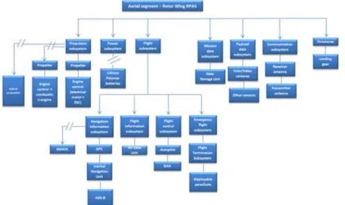
Fig. 1. RPAS model, aerial segment. 2
MATEC Web of Conferences 231, 00002 (2018) https://doi.org/10.1051/matecconf/201823100002 GAMBIT 2018
2
MATEC Web of Conferences 233, 00002 (2018) https://doi.org/10.1051/matecconf/201823300002 EASN-CEAS 2018
RPAS will probably bring economic benefits in terms of competitiveness in many economic activities like agriculture, communication industry, monitoring/inspection of infrastructures; transport and logistics, energy delivery. RPAS will preserve human beings from fatal injuries or death while performing aerial works. In addition, RPAS diffusion will create new jobs and professional figures: the remote pilot/operator, the RPAS manufacturer, the analyst of engineering data collected by RPAS during operational sorties [1]. For the moment, RPAS only, as a subset of Unmanned Aerial Systems (UAS), remotely piloted by a human pilot on ground, will be effectively allowed to be integrated into controlled airspaces [2].The key to fully realize these scenarios will be the full and safe integration of RPAS into controlled airspaces alongside manned aircraft. Therefore, as it happens for manned aircraft, reliability of RPAS subsystems and components shall be considered and demonstrated. ‘Failure Modes and Effect and Criticality Analysis’ (FMECA) and ‘Fault Tree Analysis’ (FTA) are traditional techniques applied in design and development phases of manned aircraft. This article shows an example of application of these methodologies to RPAS. Physically, RPAS is a ‘system of systems’ composed of [2] the aerial segment (rotor wing or fixed wing RPAS or hybrid RPAS), the ground segment (a portable radiocontroller or a ground control station), the Communication, Command and Control (C3) radiolink to send commands to the aerial segment and to receive telemetry from the aircraft. Rotor wing RPAS are powered by electric motors; fixed wing RPAS are powered by combustion engines (with propellers or not); hybrid RPAS are driven by electric engines powered by hydrogen fuel cells to enhance their range and endurance. This paper is organized as follows: Section 1 is an introduction; Section 2 describes FMECA and FTA methodologies; Section 3 shows the RPAS architecture used for the analyses; Section 4 shows analyses results; finally, Section 5 sums up the conclusions and open points for future works.
2 The Failure Modes and Effects and Criticality Analysis
(FMECA) and the Fault Tree Analysis (FTA) methodologies
The reliability of a given system is the probability that it performs its mission for the intended period of time under given operating conditions. An unmanned system will be considered reliable if it is fully operative at the start-up, then during pre-flight test, and during the whole assigned mission until engines shut down on ground [3]. The Failure Modes and Effect Analysis (FMEA) and Fault Tree Analysis (FTA) are classical methodologies widely described in aeronautical literature and systematicaly used in manned aviation to study systems reliability. The FMEA was born in the 1940s in defence and nuclear sectors and it was formally adopted by NASA in the 1960s when space program activities began [3]. It is a design and decisional tool useful to identify all failure modes and effects of a system [4]. Each failure mode is ranked according to its severity [4]. that is the worst potential consequence (in terms of human beings injury, or third property or system damage) that could ultimately occur [4]. The failure mode is the manner in which the failure occurs. A failure cause can be a physical, a chemical process, a quality defect, a part misapplication or any other process capable of causing a failure or a stating deterioration phenomenon that can provoke a failure. A failure mode effect is a possible consequence of a given failure mode that can occur at local, next higher or end effect level [4]. An extended version of FMEA analysis has been considered in this paper: the FMECA, that is the ‘Failure Modes and Effects and Criticality Analysis’ [4]. The ‘Criticality Analysis’ is a further part of the analysis to rank each potential failure mode according to its combination of severity and probability of occurrence [4]. The criticality analysis is completed with the evaluation of the most proper assurances and controls applicable for limiting the probability of occurrence of the considered failure mode [4].
The purpose of FMEA or FMECA analysis, is the identification of single point of failures that finally are collected in a report draft according to the FMECA template foreseen by [4] at task 103. A single point of failure is the failure of an item able to lead in the failure of the system and which is not compensated by any redundancy or operational procedure [3]. Single point of failures can be mitigated implementing fault tolerance or fault avoidance strategies. Fault tolerance strategies are achieved using hardware redundancy schemes arranged in duplicated, triplicated or quadruplicated configurations so to tolerate the given failure when it occurs [5]. Fault avoidance is implemented replacing the components which mostly compromise the reliability of the system with other more reliable ones [5]. The Fault Tree Analysis (FTA) is a reliability analysis methodology that allows to identify combination of events that lead to the loss of a specific system functionality or to system failure. It is performed implementing the so called fault trees, where the components of the system are graphically linked among them through logical connections. The FMECA is an inductive process while the FTA is a deductive process. They both can be performed from a qualitative or a quantitative point of view [4]. The example of FMECA and FTA results reported in this paper have been obtained performing a qualitative analysis due to the lack for the moment of RPAS equipment reliability data. As indicated in literature [4], reliability data come from targeted tests run coupling the exact operating conditions of the considered item. The purpose of the performed analysis was not to evaluate the effective reliability of a given RPAS components, but to investigate the adequacy and utility of FMECA methodology for RPAS within a more comprehensive risk assessment study applied to unmanned systems. For each considered RPAS functional subsystem the qualitative FTA analysis has been perfomed investigating the main combinations of events that can lead to its loss. The combinations of two, three or four events have been solved applying Boolean Algebra to related truth tables or Karnaugh maps (cases of combinations of up to five o six events). Other further more complex cases have been left out as less significant for the purpose of the present study. The FMECA analysis object of this paper has been performed according to the Military Standard 1629 Revision A (MIL-STD-1629A) issued by the Department of Defence of the United States of America in 1980 [4]. The FTA analysis object of this paper has been performed according to the Military Handbook 338 Revision B issued by the Department of Defence of the United States of America in 1998 (MIL-HDBK- 338B) [6].
Fig. 2. RPAS model, C3 radio link.
Fig. 3. RPAS model, ground segment.
3 The RPAS model
The RPAS model used for the analyses is shown in figure 1, figure 2 and figure 3.
RPAS subsystems and related functionalities have been allocated according to RPAS typical operative mission phases as per the content of figure 4 and Table 1.
Fig. 4. RPAS flight mission phases
Table 1. RPAS functionalities allocation vs. mission phases
RPAS Subsystems Mission phases (Rotor wing RPAS) Start-up Subsystem 1, 2 3 4 5 6 7 8, 9
Structures X X X X X X X
Propulsion Subsystem X X X X X X X
Power Subsystem X X X X X X X
Flight Navigation Subsystem - X X X X X - Flight Information Subsystem - X X X X X - Flight Control Subsystem - X X X X X - Emergency Flight Subsystem - X X X X X - Mission Data Subsystem X X X X X X X Payload Data Subsystem - - - X - - - Communication Command and Control subsystem X X X X X X X Ground Control Station subsystem X X X X X X X
The FMECA analysis has been performed considering for every RPAS subsystem the possible equipment single failure modes. Each failure mode has been coded and characterized in terms of effects on the subsystem it belongs to (local, higher and next level), mission phase affected (Figure 4 and Table 1), severity of consequences ([4] para. 4.4.3), probability of occurrence ([4], Task 102, Para. 3.1), detectability level ([4], Task 101, Para. 5.1), criticality ranking ([4], Task 102, Figure 102.2) and possible compensation provisions or mitigation actions ([4], Task 101, Para 5.7). A FMECA process analysis on human figures involved into RPAS operations (the remote pilot, the pilot on board manned aircraft and the Air Traffic Controller (ATC)) has been performed to complete the analysis. Human Factor Analysis and Classification System (HFACS) model [7] elaborated by Prof. James Reason has been used to identify human operator failure modes in terms of errors and violations having an impact on the RPAS system/mission exactly as in case of RPAS technical single or combined failures. The FTA analysis has been performed focusing on RPAS functionalities associated to each RPAS subsystem listed in Table 1 identifying and considering possible combinations of events/faults. The fault trees have been implemented according to the criteria and symbology contained in [6]. In this paper Automatic Surveillance Dependant – Broadcast (ADS-B) FMECA analysis and Detect and Avoid (DAA) functionality (under Flight Control subsystem) FTA analysis have been reported in Section 4 as examples of the performed work. Such topics have been preferred for the paper among the others included into unmanned systems for their crucial safety role in the incoming integration of RPAS into controlled airspace besides manned aircraft ([8], [9]).
4 FMECA and FTA analyses results
The results of FMECA analysis of an ‘Automatic Dependant Surveillance Broadcast’ (ADS-B) equipment [8] and the results of FTA analysis for an RPAS ‘Detect and Avoid’ (DAA) functionality (including ADS-B) are reported hereinafter. The following possible ADS-B single points of failure of ADS-B have been identified starting from data available in literature for manned aircraft ([8] and [10] for probability of occurrence and detectability methods for example) and evaluated as described in Section 2.
Results: ADS-B loss of position accuracy (Probability of occurrence: E, Failure consequence level ‘Catastrophic’, Detection method: ‘None’); GPS receiver unit fault (Probability of occurrence: E, Failure consequence level ‘Catastrophic’, Detection method: ‘None’); ADS-B out antenna deterioration (Probability of occurrence: D, Failure consequence level ‘Catastrophic’, Detection method: ‘None’); broadcast of incorrect data (Probability of occurrence: E, Failure consequence level ‘Catastrophic’, Detection method: ‘None’); Broadcast of ADS-B distorted data (Probability of occurrence: D, Failure consequence level ‘Catastrophic’, Detection method: ‘None’); ADS-B emitter transponder fault (Probability of occurrence: E, Failure consequence level ‘Catastrophic’, Detection method: ‘None’); erroneous altitude data (Probability of occurrence: C, Failure consequence level ‘Catastrophic’, Detection method: ‘None); data encoding error (Probability of occurrence: E, Failure consequence level ‘Catastrophic’, Detection method: ‘None’); loss of ADS-B position data to be sent to the emitter (Probability of occurrence: E, Failure consequence level ‘Catastrophic’, Detection method: ‘Visual or audible warning devices’); abrupt interruption of ADS-B service (Probability of occurrence: B, Failure consequence level ‘Catastrophic’, Detection method: ‘Visual or audible warning devices’); abrupt lack of GPS data to ADS-B (Probability of occurrence: E; Failure consequence level ‘Catastrophic’, Detection method: ‘Visual or audible warning devices’); degradation of data accuracy sent by the satellite to the ADS-B (Probability of occurrence: C; Failure consequence level ‘Catastrophic’, Detection method: ‘Visual or audible warning devices’); loss of satellite integrity signal (Probability of occurrence: E; Failure consequence level
4
MATEC Web of Conferences 231, 00002 (2018) https://doi.org/10.1051/matecconf/201823100002 GAMBIT 2018
4
MATEC Web of Conferences 233, 00002 (2018) https://doi.org/10.1051/matecconf/201823300002 EASN-CEAS 2018
Fig. 2. RPAS model, C3 radio link.
Fig. 3. RPAS model, ground segment.
3 The RPAS model
The RPAS model used for the analyses is shown in figure 1, figure 2 and figure 3.
RPAS subsystems and related functionalities have been allocated according to RPAS typical operative mission phases as per the content of figure 4 and Table 1.
Fig. 4. RPAS flight mission phases
Table 1. RPAS functionalities allocation vs. mission phases
RPAS Subsystems Mission phases (Rotor wing RPAS) Start-up Subsystem 1, 2 3 4 5 6 7 8, 9
Structures X X X X X X X
Propulsion Subsystem X X X X X X X
Power Subsystem X X X X X X X
Flight Navigation Subsystem - X X X X X - Flight Information Subsystem - X X X X X - Flight Control Subsystem - X X X X X - Emergency Flight Subsystem - X X X X X - Mission Data Subsystem X X X X X X X Payload Data Subsystem - - - X - - - Communication Command and Control subsystem X X X X X X X Ground Control Station subsystem X X X X X X X
The FMECA analysis has been performed considering for every RPAS subsystem the possible equipment single failure modes. Each failure mode has been coded and characterized in terms of effects on the subsystem it belongs to (local, higher and next level), mission phase affected (Figure 4 and Table 1), severity of consequences ([4] para. 4.4.3), probability of occurrence ([4], Task 102, Para. 3.1), detectability level ([4], Task 101, Para. 5.1), criticality ranking ([4], Task 102, Figure 102.2) and possible compensation provisions or mitigation actions ([4], Task 101, Para 5.7). A FMECA process analysis on human figures involved into RPAS operations (the remote pilot, the pilot on board manned aircraft and the Air Traffic Controller (ATC)) has been performed to complete the analysis. Human Factor Analysis and Classification System (HFACS) model [7] elaborated by Prof. James Reason has been used to identify human operator failure modes in terms of errors and violations having an impact on the RPAS system/mission exactly as in case of RPAS technical single or combined failures. The FTA analysis has been performed focusing on RPAS functionalities associated to each RPAS subsystem listed in Table 1 identifying and considering possible combinations of events/faults. The fault trees have been implemented according to the criteria and symbology contained in [6]. In this paper Automatic Surveillance Dependant – Broadcast (ADS-B) FMECA analysis and Detect and Avoid (DAA) functionality (under Flight Control subsystem) FTA analysis have been reported in Section 4 as examples of the performed work. Such topics have been preferred for the paper among the others included into unmanned systems for their crucial safety role in the incoming integration of RPAS into controlled airspace besides manned aircraft ([8], [9]).
4 FMECA and FTA analyses results
The results of FMECA analysis of an ‘Automatic Dependant Surveillance Broadcast’ (ADS-B) equipment [8] and the results of FTA analysis for an RPAS ‘Detect and Avoid’ (DAA) functionality (including ADS-B) are reported hereinafter. The following possible ADS-B single points of failure of ADS-B have been identified starting from data available in literature for manned aircraft ([8] and [10] for probability of occurrence and detectability methods for example) and evaluated as described in Section 2.
Results: ADS-B loss of position accuracy (Probability of occurrence: E, Failure consequence level ‘Catastrophic’, Detection method: ‘None’); GPS receiver unit fault (Probability of occurrence: E, Failure consequence level ‘Catastrophic’, Detection method: ‘None’); ADS-B out antenna deterioration (Probability of occurrence: D, Failure consequence level ‘Catastrophic’, Detection method: ‘None’); broadcast of incorrect data (Probability of occurrence: E, Failure consequence level ‘Catastrophic’, Detection method: ‘None’); Broadcast of ADS-B distorted data (Probability of occurrence: D, Failure consequence level ‘Catastrophic’, Detection method: ‘None’); ADS-B emitter transponder fault (Probability of occurrence: E, Failure consequence level ‘Catastrophic’, Detection method: ‘None’); erroneous altitude data (Probability of occurrence: C, Failure consequence level ‘Catastrophic’, Detection method: ‘None); data encoding error (Probability of occurrence: E, Failure consequence level ‘Catastrophic’, Detection method: ‘None’); loss of ADS-B position data to be sent to the emitter (Probability of occurrence: E, Failure consequence level ‘Catastrophic’, Detection method: ‘Visual or audible warning devices’); abrupt interruption of ADS-B service (Probability of occurrence: B, Failure consequence level ‘Catastrophic’, Detection method: ‘Visual or audible warning devices’); abrupt lack of GPS data to ADS-B (Probability of occurrence: E; Failure consequence level ‘Catastrophic’, Detection method: ‘Visual or audible warning devices’); degradation of data accuracy sent by the satellite to the ADS-B (Probability of occurrence: C; Failure consequence level ‘Catastrophic’, Detection method: ‘Visual or audible warning devices’); loss of satellite integrity signal (Probability of occurrence: E; Failure consequence level
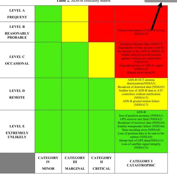
‘Catastrophic’, Detection method: ‘Visual or audible warning devices’); sudden delayed aircraft position updates without any notification (Probability of occurrence: C, failure consequence level ‘Catastrophic’, Detection method: ‘Visual or audible warning devices’); sudden loss of ADS-B data to ATC controllers (Probability of occurrence: D, failure consequence level ‘Catastrophic’, Detection method: ‘Visual or audible warning devices’); degradation loss of ADS-B data-link (Probability of occurrence: C, failure consequence level ‘Catastrophic’, Detection method: ‘Visual or audible warning devices’); ADS-B ground station failure (Probability of occurrence: D, failure consequence level ‘Catastrophic’, Detection method: ‘Visual or audible warning devices’); human error (Probability of occurrence: D, failure consequence level ‘Catastrophic’, Detection method: ‘None’). Table 2 shows the final ADS-B resulting criticality matrix. The severity of occurrence has been classified by the Authors as ‘Catastrophic (Level I) for every given failure mode. The reason is that ADS-B loss or degradation of performance can affect the safety of the RPAS reasonably enhancing the probability of occurrence of mid-air collisions between manned aircraft and RPAS or between RPAS if flying on the same route. According to [8], most failure modes are undetectable from the remote pilot; in the best cases visual or audible warning devices can be foreseen for his situational awareness. In general, preventive measures can be adopted in terms of design solutions or systematic operator actions like regular maintenance and testing of ADS-B avionic equipment. For example, redundancy with EGNOS (more reliable than GPS thanks to Receiver Autonomous Integrity Monitoring (RAIM) or Fault Detection and Exclusion (FDE) functions) can be indicated in case of loss or degradation of GPS ; or redundancy with inertial navigation systems are indicated in case of abrupt interruption of ADS-B service or abrupt lack of sending position to ADS-B [8]. Avionics maintenance actions can be suggested in case of ADS-B out antenna deterioration, altimeter failure, encoder errors or delayed or wrong aircraft position for ATC operators. Preventive cyber countermeasures are recommended against intentional or unintentional radio frequency interference occurrence or more specifically against malicious jamming against ADS-B signals Looking forward to incoming diffusion of RPAS into the controlled airspace, proper design requirements sized on the given RPAS category against electromagnetic interference both from external and internal RF sources can be recommended.
The ADS-B failure affects the ‘Detect and Avoid’ functionality [11] due to the loss of RPAS/aircraft position information. This fact leads to the consequent lack of input to the autopilot to command proper evasive manoeuvres to avoid potential collisions. The degradation of DAA functionality has been formally expressed implementing a simple model of DAA fault tree and solving the related truth table with three variables. More precisely, the combinations of GPS, altimeter or ADS_B failures suggest the potential occurrence of hazards like ‘Loss of separation’ and ‘Mid-air collisions’.
5 Discussion and conclusions
This paper shows an example of application of RPAS of reliability analysis tecniques to RPAS. The obtained results confirm the value of FMECA and FTA as decisional tools for RPAS too as systematic methodologies to find out single or combined failures that are potential sources of technical hazard for RPAS. Reasoning about ADS-B and DAA failures, it is easy to imagine the hidden hazards. Wrong RPAS position indication provided by ADS-B to other traffic implies misleading separations and distances from other aircraft and human operators loss of situational awareness: the hidden hazard results to be mid-air collision. DAA malfunction due to ADS-B failure standalone or combined with GPS or altimeter failures can lead to the lack of performance of correct evasive manoeuvres.
Again, the risk of a mid-air collision can occur as worst consequences with the highest severe consequence: loss of RPAS, loss of RPAS mission and loss of economic gain related to the the RPAS mission. A high value can be recognized to FMECA and FTA while RPAS are now object of great interest and attention from international aviation community. With reference to the present study, an extended FMECA/FTA evaluation has been performed on a complete RPAS architecture to find out more technical failures. Then these data have been evaluated in terms of risk assessment to implement a more comprehensive risk matrix including hazards coming from the operational environment where RPAS will fly and hazards caused by weather conditions. As discussed in Section 4, useful design indications can derive from reasoning about reliability analyses results like when and how implement equipment redundancy or when focusing on proper maintenance actions. From this point of view, another possible extension of the present study is carrying out systematic analyses to identify the most critical issues to focus on when defining requirements for future RPAS airworthiness certification.
Table 2. ADS-B criticality matrix LEVEL A
FREQUENT LEVEL B REASONABLY
PROBABLE
Abrupt interruption of ADS-B service (NISSA10)
LEVEL C OCCASIONAL
Erroneous altitude Data (NISSA7) Degradation of data accuracy sent by the satellite to the ADS-B (NISSA12) Sudden delayed aircraft position updates without any notification
(NISSA14) Degradation/loss of ADS-B signal
(NISSA16) Human error (nissa18)
LEVEL D REMOTE
ADS-B OUT antenna deterioration(NISSA3) Broadcast of distorted data (NISSA5)
Sudden loss of ADS-B data to ATC controllers without notification
(NISSA15) ADS-B ground station failure
(NISSA17)
LEVEL E EXTREMELY
UNLIKELY
ADS-B
loss of position accuracy (NISSA1) GPS receiver unit fault (NISSA2) Broadcast of incorrect data (NISSA4) Emitter transponder failure (NISSA6)
Data encoding error (NISSA8) Loss of position data to be sent to the
emitter (NISSA9) Abrupt lack of GPS data(NISSA11)
Loss of satellite signal integrity (NISSA13) CATEGORY IV MINOR CATEGORY III MARGINAL CATEGORY II CRITICAL CATEGORY I CATASTROPHIC CRITICALITY 6
MATEC Web of Conferences 231, 00002 (2018) https://doi.org/10.1051/matecconf/201823100002 GAMBIT 2018
6
MATEC Web of Conferences 233, 00002 (2018) https://doi.org/10.1051/matecconf/201823300002 EASN-CEAS 2018
‘Catastrophic’, Detection method: ‘Visual or audible warning devices’); sudden delayed aircraft position updates without any notification (Probability of occurrence: C, failure consequence level ‘Catastrophic’, Detection method: ‘Visual or audible warning devices’); sudden loss of ADS-B data to ATC controllers (Probability of occurrence: D, failure consequence level ‘Catastrophic’, Detection method: ‘Visual or audible warning devices’); degradation loss of ADS-B data-link (Probability of occurrence: C, failure consequence level ‘Catastrophic’, Detection method: ‘Visual or audible warning devices’); ADS-B ground station failure (Probability of occurrence: D, failure consequence level ‘Catastrophic’, Detection method: ‘Visual or audible warning devices’); human error (Probability of occurrence: D, failure consequence level ‘Catastrophic’, Detection method: ‘None’). Table 2 shows the final ADS-B resulting criticality matrix. The severity of occurrence has been classified by the Authors as ‘Catastrophic (Level I) for every given failure mode. The reason is that ADS-B loss or degradation of performance can affect the safety of the RPAS reasonably enhancing the probability of occurrence of mid-air collisions between manned aircraft and RPAS or between RPAS if flying on the same route. According to [8], most failure modes are undetectable from the remote pilot; in the best cases visual or audible warning devices can be foreseen for his situational awareness. In general, preventive measures can be adopted in terms of design solutions or systematic operator actions like regular maintenance and testing of ADS-B avionic equipment. For example, redundancy with EGNOS (more reliable than GPS thanks to Receiver Autonomous Integrity Monitoring (RAIM) or Fault Detection and Exclusion (FDE) functions) can be indicated in case of loss or degradation of GPS ; or redundancy with inertial navigation systems are indicated in case of abrupt interruption of ADS-B service or abrupt lack of sending position to ADS-B [8]. Avionics maintenance actions can be suggested in case of ADS-B out antenna deterioration, altimeter failure, encoder errors or delayed or wrong aircraft position for ATC operators. Preventive cyber countermeasures are recommended against intentional or unintentional radio frequency interference occurrence or more specifically against malicious jamming against ADS-B signals Looking forward to incoming diffusion of RPAS into the controlled airspace, proper design requirements sized on the given RPAS category against electromagnetic interference both from external and internal RF sources can be recommended.
The ADS-B failure affects the ‘Detect and Avoid’ functionality [11] due to the loss of RPAS/aircraft position information. This fact leads to the consequent lack of input to the autopilot to command proper evasive manoeuvres to avoid potential collisions. The degradation of DAA functionality has been formally expressed implementing a simple model of DAA fault tree and solving the related truth table with three variables. More precisely, the combinations of GPS, altimeter or ADS_B failures suggest the potential occurrence of hazards like ‘Loss of separation’ and ‘Mid-air collisions’.
5 Discussion and conclusions
This paper shows an example of application of RPAS of reliability analysis tecniques to RPAS. The obtained results confirm the value of FMECA and FTA as decisional tools for RPAS too as systematic methodologies to find out single or combined failures that are potential sources of technical hazard for RPAS. Reasoning about ADS-B and DAA failures, it is easy to imagine the hidden hazards. Wrong RPAS position indication provided by ADS-B to other traffic implies misleading separations and distances from other aircraft and human operators loss of situational awareness: the hidden hazard results to be mid-air collision. DAA malfunction due to ADS-B failure standalone or combined with GPS or altimeter failures can lead to the lack of performance of correct evasive manoeuvres.
Again, the risk of a mid-air collision can occur as worst consequences with the highest severe consequence: loss of RPAS, loss of RPAS mission and loss of economic gain related to the the RPAS mission. A high value can be recognized to FMECA and FTA while RPAS are now object of great interest and attention from international aviation community. With reference to the present study, an extended FMECA/FTA evaluation has been performed on a complete RPAS architecture to find out more technical failures. Then these data have been evaluated in terms of risk assessment to implement a more comprehensive risk matrix including hazards coming from the operational environment where RPAS will fly and hazards caused by weather conditions. As discussed in Section 4, useful design indications can derive from reasoning about reliability analyses results like when and how implement equipment redundancy or when focusing on proper maintenance actions. From this point of view, another possible extension of the present study is carrying out systematic analyses to identify the most critical issues to focus on when defining requirements for future RPAS airworthiness certification.
Table 2. ADS-B criticality matrix LEVEL A
FREQUENT LEVEL B REASONABLY
PROBABLE
Abrupt interruption of ADS-B service (NISSA10)
LEVEL C OCCASIONAL
Erroneous altitude Data (NISSA7) Degradation of data accuracy sent by the satellite to the ADS-B (NISSA12) Sudden delayed aircraft position updates without any notification
(NISSA14) Degradation/loss of ADS-B signal
(NISSA16) Human error (nissa18)
LEVEL D REMOTE
ADS-B OUT antenna deterioration(NISSA3) Broadcast of distorted data (NISSA5)
Sudden loss of ADS-B data to ATC controllers without notification
(NISSA15) ADS-B ground station failure
(NISSA17)
LEVEL E EXTREMELY
UNLIKELY
ADS-B
loss of position accuracy (NISSA1) GPS receiver unit fault (NISSA2) Broadcast of incorrect data (NISSA4) Emitter transponder failure (NISSA6)
Data encoding error (NISSA8) Loss of position data to be sent to the
emitter (NISSA9) Abrupt lack of GPS data(NISSA11)
Loss of satellite signal integrity (NISSA13) CATEGORY IV MINOR CATEGORY III MARGINAL CATEGORY II CRITICAL CATEGORY I CATASTROPHIC CRITICALITY
References
1. European Commission Staff Working Document, Impact assessment (Brussel, 2015) 2. International Civil Aviation Organization (ICAO), Circular no. 328/AN 190
Unmanned Aircraft Systems (ICAO, 2011)
3. B. J. de Oliveira Martins Franco, L. C. Sandoval Góes, Failure analysis methods in Unmanned Aerial Vehicles, (Proceedings of COBEM 2007, 19th International Congress of Mechanical Engineering, © 2007 by ABCM)
4. Military Standard 1629 Rev. A, (United States of America, Department of Defence, 1980)
5. S. Kabir, An overview of fault tree analysis and its application in model based dependability analysis (ELSEVIER, Expert Systems With Applications 77, 114–135, 2017)
6. Military Handbook 338 Rev. B (United States of America, Department of Defence 1998)
7. J. Reason, Human Error (Cambridge University Press, 1990)
8. B. Syd Ali, W. Ochieng, A. Majumdar, W. Schuster, T. K. Chiew, ADS-B failure mode and models (The Journal of Navigation, 67, 995–1017. © The Royal Institute of Navigation, 2014)
9. Single European Sky ATM Research Joint Undertaking (SESAR JU). Demonstrating RPAS Integration in the European Aviation System A Summary of SESAR Drone Demonstration Projects Results (SESAR Joint Undertaking, Bruxelles, Belgium, 2016; pp. 1–28)
10. B. Syd Ali, W. Ochieng, A. Majumdar, ADS-B probabilistic safety assessment (The Journal of Navigation, pages 1, 20. © The Royal Institute of Navigation, 2017)
11. Centro Italiano Ricerche Aerospaziali (CIRA). SESAR Joint Undertaking RPAS 0.3 RAID Demonstration Report (1st ed., SESAR Joint Undertaking, Bruxelles, Belgium, 2016, pp. 1–156)
8
MATEC Web of Conferences 231, 00002 (2018) https://doi.org/10.1051/matecconf/201823100002 GAMBIT 2018
8
MATEC Web of Conferences 233, 00002 (2018) https://doi.org/10.1051/matecconf/201823300002 EASN-CEAS 2018