Corresponding author: Ahmad Ghanbari
Email: [email protected]
WWW.ENGINEERSPRESS.COM
World of Sciences Journal
www.engineerspress.com
Year: 2013 Volume: 1 Issue: 8
Pages: 148-158
Aahmad Ghanbari
1, 2, Arash Rahmani
11
Department of Mechanical Engineering, University of Tabriz, Tabriz, Iran
2
School of Engineering Emerging Technologies, Mechatronics Laboratory,
University of Tabriz, Tabriz, Iran
ABSTRACT
KEYWORDS:
Artificial neural networks, kinematic Analysis, Multi-layer perceptron, Radial
basis function.
●
●
●
This paper presents forward and inverse Kinematics analysis of a specific class of series–
parallel manipulators, known as 2(6-UPS) manipulators. As Forward kinematics problem of
this kind of manipulators is a very difficult problem to solve because of their highly nonlinear
relations between joint variables and position and orientation of the end effectors, Numerical
methods are the most common approaches to solve. Nevertheless, the possible lack of
convergence of these methods is the main drawback. Therefore, artificial neural networks
(ANN) with their inherent learning ability as a strong method, was used to approximate the
forward kinematics function without any knowledge of manipulator structure. In this paper, two
types of ANN models were used. MLP (multi-layer perceptron network) and RBF (radial basis
function network) have been used to solve the forward kinematics problem of this hybrid
manipulator and results are obtained. Simulation results show the advantages of employing
neural networks. Also, according to average percentage error, as the performance index, it
was found at RBF gives better result as compared to MLP.
●
●
●
Neural Network Solutions for Forward
Kinematics Problem of Hybrid Serial-Parallel
Manipulator
Corresponding author: Ahmad Ghanbari
Email: [email protected]
WWW.ENGINEERSPRESS.COM
World of Sciences Journal
1.
I
NTRODUCTIONA hybrid manipulation system is a sequence of parallel mechanisms which can overcome the limited workspace of parallel mechanism and can provide feature of both serial and parallel mechanism. They are able to achieve high stiffness and high force-to-weight ratio. Many different types of hybrid robots have been investigated in [1-4]. Tanio [5] presented a hybrid (parallel serial) manipulator consisting of two serially connected parallel mechanism and gave it’s closed-form solution for forward and inverse position problems. Romdhane’s [6] hybrid manipulator is also made of a base and two platforms in series and the motion of the mid platform is restricted only to three translations and the second platform rotates spherically with respect to the mid platform using joint connected the mid platform and top platform. Huang et al. [7] studied the characteristics of 6 DOF parallel–serial hybrid manipulators which features a 3 DOF in series actuated module mounted on the moving plate of another 3 DOF in parallel actuated manipulator with prismatic actuators. Yang et al. [8] discussed the kinematics of hybrid type manipulation system with 6 DOF, which consist of a 3-DOF planar parallel platform and a 3-DOF serial robot arm. Huang et al. [9] studied a conceptual design and dimensional synthesis of a 3-DOF parallel mechanism module which forms the main body of a newly invented 5-DOF reconfigurable hybrid robot. LiangZhi et al. [10] studied a hybrid 5DOF manipulator based on the novel 3-RPS inactuated parallel manipulator. In their design a 2DOF serial working table is placed over the mobile platform. Campos et al. [11] presented a new methodology to synthesize hybrid robots as a whole structure. Their method is based on Assure groups as the simplest basic blocks to build kinematic chains. Gallardo-Alvarado et al. [12] studied Kinematics and dynamics of 2(3-RPS) manipulators by means of screw theory and the principle of virtual work. Mohammadipanah et al. [13] Design and Analysis of a Novel 8-DOF Hybrid Manipulator that is appropriate for the stated applications by connecting two serial and parallel mechanisms. Bing Li et al. [14] used a hybrid manipulator as a multi-dimensional vibration isolator based on the parallel mechanism. The scheme design, inverse kinematics, workspace and dexterity are carried out in their paper.
In this paper a novel hybrid robot 2(6-UPS) is introduced that composed a sequence of two same stewart mechanism modules. The serial form of these hybrid manipulators overcomes the limited workspace of parallel manipulators and improves overall stiffness and response characteristics. Then inverse and forward kinematics solution is presented for it. Because of their highly nonlinear relations between joint variables and position and orientation of the end effectors, two types of ANN models - MLP (multi-layer perceptron network) and RBF (radial basis function network) - have been used to solve the forward kinematics.
This paper is organized as follows: In Section 2, description of the robot is discussed. In Section 3, the inverse and forward kinematic solutions are presented in the closed form. MLP network and RBF method to solve forward kinematic (FK) are discussed in section 4. In section 5 the results of solving FK for 2(6-UPS) manipulator robot by these networks are presented. Comparison of these networks and conclusion are discussed in section 6.
2.
DESCRIPTION
OF
THE
HYBRID
ROBOT
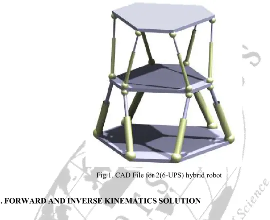
The mechanism under investigation in this paper consists of two same modules that each module is Stewart Platform mechanism with 6 DOFs. In this hybrid mechanism, we have three platforms and twelve pods. Base platform is stationary and connected to middle platform via 6 extensible pods. Also, middle platform is connected to upper platform (as an end effecter) via 6 extensible pods. Each pod connects to the platform at its connection point through a spherical joint, and to the base at its connection point through universal joint. Each pod consists of two parts: the upper part and the lower part, which connect to each other through prismatic joint. Therefore, it is referred to as the 2(6-UPS) mechanism. This manipulator is actuated by motors located on the prismatic joints. Figure 1 shows the design of the mentioned hybrid robot.
Corresponding author: Ahmad Ghanbari
Email: [email protected]
WWW.ENGINEERSPRESS.COM
World of Sciences Journal
6
,....,
2
,
1
=
−
=
op
b
for
i
L
i i i ) . ( i i i D Rcp op = +Fig.1. CAD File for 2(6-UPS) hybrid robot
3.
FORWARD
AND
INVERSE
KINEMATICS
SOLUTION
Mechanism kinematics deals with the study of the mechanism motion as constrained by the geometry of the links. Typically, the study of mechanism kinematics is divided into two parts: inverse kinematics and direct kinematics. About mentioned hybrid robot, the inverse kinematics problem involves mapping a known pose (position and orientation) of the moving platforms of the mechanism to a length of each module’s pods. The direct kinematics problem involves the mapping from a known length of each module’s pods to a pose of the moving platforms. In this section the inverse and forward kinematics problems of proposed mechanism are described in closed form.
Figure 2 shows the vectorial representation of theith pod at each module. According to fig. 2, the middle and upper
moving platforms frame are shown by {C} and {C′} respectively and base frame with{O}. Also, ) , , , , , (x y zα β γ
X = and X′=(x′,y′,z′,α′,β′,γ′) present the location and orientation of the middle and upper moving platform respectively. Now, the inverse kinematics of each module is obtained at first, and then forward kinematics is considered. Inverse Kinematic problem of the platforms involves determination of the linear position, of six Pods for each module through considering a specified position, of the middle and upper moving platforms centre.
A. Middle Moving Platform
The length vector of the ithpod in the upper module can be obtained as:
(1)
Corresponding author: Ahmad Ghanbari
Email: [email protected]
WWW.ENGINEERSPRESS.COM
World of Sciences Journal
= 33 23 13 23 22 21 13 12 11 R R R R R R R R R R = = = = zi yi xi i zi yi xi i z y x i p p p cp b b b b D D D D D , , r r r
−
+
+
+
−
+
+
+
−
+
+
+
=
=
zi zi yi xi z yi zi yi xi y xi zi yi xi x zi yi xi ib
p
R
p
R
p
R
D
b
p
R
p
R
p
R
D
b
p
R
p
R
p
R
D
L
L
L
L
33 32 31 23 22 21 13 12 11Fig.2. vectorial representation of the th
i pod at each module
Where R is the rotation 3×3 matrix, representing the rotation of frame{C}related to frame{O}and it is defined if ) , , , , , (x y zα β γ X= is obvious: (3) Also, (4)
Using equation (1) to (4), the length of the ith pod,Li, for base module can be expressed as:
(5) Upper Module Base Module } {O } {C } {C′ i p′ i p i D′ r i D r i L′ r i L r i
cp
i p c′ ′ i B i b r x y zCorresponding author: Ahmad Ghanbari
Email: [email protected]
WWW.ENGINEERSPRESS.COM
World of Sciences Journal
2 2 2 zi yi xi i
L
L
L
L
=
+
+
6
,....,
2
,
1
=
−
′
=
′
o
p
op
for
i
L
i i i6
,....,
2
,
1
.
.
′
+
′
′
′
=
+
=
′
D
R
D
R
R
c
p
for
i
p
o
i i i i = ′ = 33 23 13 23 22 21 13 12 11 H H H H H H H H H R R H ′ ′ ′ = ′ ′ ′ ′ ′ = ′ = ′ zi yi xi i z y x i p p p p c D D D D D , r r
−
−
−
′
+
′
+
′
+
′
+
′
+
′
−
−
−
′
+
′
+
′
+
′
+
′
+
′
−
−
−
′
+
′
+
′
+
′
+
′
+
′
=
′
′
′
=
′
zi yi xi zi yi xi z y x zi yi xi zi yi xi z y x zi yi xi zi yi xi z y x zi yi xi ip
R
p
R
p
R
p
H
p
H
p
H
D
R
D
R
D
R
p
R
p
R
p
R
p
H
p
H
p
H
D
R
D
R
D
R
p
R
p
R
p
R
p
H
p
H
p
H
D
R
D
R
D
R
L
L
L
L
33 32 31 33 32 31 33 32 31 23 22 21 23 22 21 23 22 21 13 12 11 13 12 11 13 12 11 (6)B. Upper Moving Platform
The length vector of the ithpod in the upper module can be obtained as:
(7)
Where:
(8)
By substituting equations (2) and (8) into Equation (7) and considering:
(9)
And:
(10)
i
L′ can be expressed as:
Corresponding author: Ahmad Ghanbari
Email: [email protected]
WWW.ENGINEERSPRESS.COM
World of Sciences Journal
2 2 2 zi yi xi i
L
L
L
L
′
=
′
+
′
+
′
0
.
)
(
=
i+
i−
i−
i=
iX
D
R
cp
b
L
f
0
.
.
.
)
(
′
=
i′
+
′
i′
−
i−
i′
=
iX
R
D
H
c
p
R
cp
L
g
r
)
tanh(
)
(
n
K
1K
2n
f
=
∑
==
N i j ij jW
x
n
1 (12) After Inverse Kinematics analysis of 2(6-UPS), we want to calculate the location and orientation of the middle and upper moving platform by knowing the length of pods at each module (Forward Kinematics). As, it is clear, we can rewrite equations (1) and (7) as below:(13)
(14) The solution of above equations is the forward kinematics problem of the mechanisms. But, because of highly nonlinear characteristic of these equations, it is so difficult to solve them. Therefore, ANN is applied to solve forward kinematics of this mechanism.
4.
ARTIFICIAL
NEURAL
NETWORKS
Artificial neural network (ANN) is a parallel-distributed information processing system. This system is composed of operators interconnected via one-way signal flow channels. ANN stores the samples with a distributed coding, thus forming a trainable nonlinear system. It includes hidden layer(s) between the inputs and outputs. The main idea of the ANN approach resembles the human brain functioning. Therefore, ANN has a quicker response and higher performance than a sequential digital computer. Given the inputs and desired outputs, it is also self-adaptive to the environment so as to respond different inputs rationally. Various neural networks have been used to solve the kinematics problem [15]. They include the multi layer perceptron network (MLPN), cerebellar model articulation controller (CMAC) and radial basis function network (RBFN). Here we use MLPN and RBFN for solution forward kinematics of 2(6-UPS) and presented a comparison between MLPN & RBFN.
A. MLPN for Kinematic Solution
The multilayer perceptron network consists of an input layer, an output layer and usually one or more hidden layers. Fig.3 shows the architecture of MLP network employed for prediction the forward kinematic solution for upper module. It has an input layer of 6 neurons, for each module, one hidden layer of 52 neurons with hyperbolic (tanh) activation function,f(n), defined by function given in bellow as:
(15)
(16)
2 1,K
K are constant coefficient. For the output layer, a linear activation function g(n)=n is used in the implementation.
The approximating function Y representing Kinematic solution is defined by Eqs. (17) and (18). This entails finding an approximating function Y representing forward kinematic solution is an N-dimensional vector.
Corresponding author: Ahmad Ghanbari
Email: [email protected]
WWW.ENGINEERSPRESS.COM
World of Sciences Journal
+
=
∑
= N j jws
f
ws
k
W
kj
b
j
A
1 1 1(
)
(
)
)
(
)
(
)
(
)
(
)
1
(
k
w
k
w
k
w
ij+
=
ij+
∆
ij)
1
(
)
(
)
(
=
−
∇
+
∆
−
∆
w
ijk
α
E
k
η
w
ijk
+
=
∑
= M j jws
W
j
b
A
g
ws
Y
1 2 2(
)
)
(
)
(
) 1 ( 1 b ) 2 ( 1 b ) 3 ( 1 b ) ( 1M b • • • • • • 1 L′ 2 L′ 3 L′ 4 L′ 5 L′ 6 L′ ) ( 3n f ) ( 2n f ) ( 1n f ) (n fM 2 b 2 b 2 b 1 g 2 g 3 g x′ y′ z′ 2 b 2 b 2 b 4 g 5 g 6 g α′ β′ γ ′ (17) (18) ) ( 1kjW is the weight between
k
thinput and jthsummation of hidden layer node; W2(j)is the weight betweenth
j hidden layer neuron and output summation node; b1(j)is the bias term applied to the th
j hidden layer neuron; )
(
2 j
b is the term applied to the output layer neuron;
ws
(
k
)
is thek
thelement of input vectorws
; Mis number of hidden layer neurons. The learning process of MLP network involves the use of the input–output data to determine the weights and biases. The training function updates the weights and bias values according to Back Propagation algorithm:(19) (20)
Where wij(k) and wij(k+1)are network weights for each layer in kand k+1step during training process,
αlearning rate,
η
momentum coefficient and Eis error function which we want to optimize it. Here α=0.55 , 75. 0
=
η
and error at the end of learning is 0.001 for training set.Corresponding author: Ahmad Ghanbari
Email: [email protected]
WWW.ENGINEERSPRESS.COM
World of Sciences Journal
∑
=+
=
M j j jh
ws
b
W
ws
Y
1 0)
(
)
(
−
−
=
∑
= N j kj j j jws
ws
c
h
1 2 2(
)
1
exp
)
(
σ
M d j 2 2 2 =σ
T
Φ
Φ)
(Φ
W
=
T −1 TB. RBF for Kinematic Solution
The RBF architecture used for the proposed the process is shown in Fig. 4. Radial basis function networks typically have three layers: an input layer, a hidden layer with a nonlinear RBF activation function and a linear output layer.
The activation function in the hidden layer of the RBF network is Gaussian, which is characterized by its response that decreases monotonically with distance from a central point. ws components that were used for MLP network are chosen. In the RBF network, Y(ws) can be expressed as a linear combination of multivariate Gaussian basis function as follows:
(21)
(22)
Where hj(ws) is the output of jth node in hidden layer,
kj
c is the center of jth RBF node for the
k
th input variablek
ws ,
j
σ is the width of Gaussian function,
j
W is the weight between jth RBF unit and output layer neuron,
0
b is the bias term and Mis the number of hidden layer neurons. The learning process of a radial basis function network involve the determination of structural configurations in terms of the number and position of basis function centers is important because it directly affects the quality of the functional approximation achieved by an RBFN. Here, the values of center are selected randomly from the training data set. The width of Gaussian radial basis function is expressed in terms of the maximum distance between the chosen center d and the number of centers M as:
(23)
Thus, after all training patterns are presented to the RBFN a M×P interpolation matrix Φ is obtained. Every row corresponds to the responses of all hidden units for each pattern and every column to each hidden unit through all patterns. In order to determine an optimal weight vector that minimizes the cost function in the least squares manner, the interpolation method is used. It can directly calculate the linear weights from target outputs and pseudo-inversion of the interpolation matrix from the following equation:
(24)
This solution produces an optimal weight vector that minimizes the cost function derived from the sum-squared error as described. Based on the given spread, RBF function iteratively adds one neuron at a time to the network until the sum squared error falls below a specified error goal or a maximum number of neurons is reached. After several trials, a three layer network architecture having 6 neurons in input layer neurons for each module, 55 neurons in hidden layer and 6 neurons in output layer neurons, for each module, is identified as the most suitable architecture. It is built with the spread constant of the Gaussian set to 0.5 and training goal of sum squared errors set to 0.001.
Corresponding author: Ahmad Ghanbari
Email: [email protected]
WWW.ENGINEERSPRESS.COM
World of Sciences Journal
Fig.4. Architecture of RBF network for forward kinematics Solution for base module
5.
R
ESULTSThe data needed for training of neural network is obtained from the inverse kinematics relations of the hybrid mechanism. The joint space of the robot can be considered as an inverse image of the Cartesian space and vice versa. Based on this, it is decided to employ inverse kinematics relations for determining the pose of each pods. The pose
L and
L ′can be used as an input and the corresponding location and orientation of middle and upper moving
platforms (X and X′) as the output for the neural network training data. In other words,
X L and X
L→ ′→ ′relationship is used while generating the data whereas X→Land X′→L′ mapping is done while training the neural network. ANN trained with such data set is found to predict forward kinematic solutions more accurately due to insignificant mapping errors between input and output data. The pose Land L′ forms the input and corresponding (X and X′)forms the output of the neural network. In order to maintain uniformity in training of ANN, a simulation data set thus obtained for training and testing of this network also consists of 1024 patterns. In this case also, 80% of total data set was used for training and remaining 20% of data was used for testing of the network. Figs 5, 6 show the result of ANN analysis by considering that the middle and upper platforms are parallel in the workspace and their orientation do not differ relative together.
0 b 0 b 0 b x y z α β γ 0 b 0 b 0 b ) (n hM ) ( 3n h ) ( 2n h • • • • • • ) ( 1n h 1 L 2 L 3 L 4 L 5 L 6 L
Corresponding author: Ahmad Ghanbari
Email: [email protected]
WWW.ENGINEERSPRESS.COM
World of Sciences Journal
Fig.5. ANN Results for Position of Middle Platform
Fig.6. ANN Results for Position of Upper Platform
6.
C
ONCLUSIONThis chapter has presented a novel hybrid robot with base of stewart mechanism and studied inverse and forward kinematics of it and the general background of artificial neural networks and applications of neural networks to the forward kinematics problem. The two most popular network types (MLPN and RBFN), used widely in kinematics approximation, have been described. The MLPN is a universal and powerful solution for almost all functional approximation applications due to its inherent nonlinear mapping capabilities which can deal with a wide range of process features. However, the training process is complex because it involves a nonlinear optimization algorithm which requires an iterative procedure and there is no reasonable mechanism to select a suitable network configuration. In contrast, the RBFN training process is simple and straightforward by using a linear optimization algorithm based on the least squares technique. There are several solutions to choose the optimal selection of the network configuration from information about the robotic system (training data) so that the generalization can be improved. However, it seems that the performance of existing approaches (both MLPNs
Corresponding author: Ahmad Ghanbari
Email: [email protected]
WWW.ENGINEERSPRESS.COM
World of Sciences Journal
and RBFNs) described earlier is still insufficiently accurate and inefficient for practical applications. For these reasons, a novel approach using an RBFN with regularly spaced position centers has been proposed to solve the kinematics problem. This solution produces an RBFN with a sufficiently small number of centers whilst achieving a satisfactory accuracy for the inverse kinematics approximation. In addition, in order to enhance the generalization of RBFNs, the concept that the constrained training data should be collected closely to the position of centers has been suggested.
R
EFERENCES[1] G. Carbone, M. Ceccarelli, “A serial–parallel robotic architecture for surgical tasks,” Robotica, Vol. 23, pp. 345–354, 2005.
[2] G. Carbone, M. Ceccarelli, “A stiffness analysis for a hybrid parallel–serial manipulator,” Robotica, Vol. 22, pp. 567–576, 2005.
[3] Bing Zhou-Yan Xu, “Robust control of a 3-DOF hybrid robot manipulator”, Int J Adv Manuf Technol, Vol. 33, pp.604–613, 2007.
[4] J.M. Rico, J. Gallardo, J. Duffy, “Screw theory and higher order kinematic analysis of open serial and closed chains”, Mechanism and Machine Theory, vol. 34, pp. 559–586, 1999.
[5] Tanio K. Tanev, “Kinematics of a hybrid (parallel-serial) robot manipulator”, Mechanism and Machine Theory, 35, pp. 1183-1196,2000.
[6] L. Romdhane, “Design and analysis of a hybrid serial–parallel manipulator”, Mechanism and Machine Theory, 34, PP. 1037-1055,1999.
[7] Ming Z. Huang, Shou-Hung Ling, Yang Sheng, “A study of velocity kinematics for hybrid manipulators with parallel–series configurations”, Robotics and Automation, IEEE Int. Conf. 1993.
[8] G. Yang, Weihai Chen Edwin, Hui L.eong Ho, “Design and Kinematic Analysis of a Modular Hybrid Parallel-Serial Manipulator”, Seventh International Conference on Control, Automation, Robotics And Vision (ICARCV'OZ), Singapore, Dec 2002.
[9] T. Huang, M. Li, X.M. Zhao, J.P. Mei, D.G. Chetwynd, S.J. Hu, “Conceptual design and dimensional synthesis for a 3-DOF module of the TriVariant—a novel 5-DOF reconfigurable hybrid robot'”, IEEE Trans. Rob., vol. 21, pp. 449–456, 2005.
[10]F. LiangZhi, A.Y. Elatta, L. XiaoPing, “Kinematic calibration for a hybrid 5DOF manipulator based on 3-RPS in-actuated parallel manipulator ”, Int J Adv Manuf Technol, vol. 25, pp. 730–734, 2005.
[11]A. Campos, Ch. Budde, J. Hesselbach, “A type synthesis method for hybrid robot structures,” Mechanism and Machine Theory, vol. 43, pp. 984–995, 2008.
[12]Jaime Gallardo-Alvarado, Carlos R. Aguilar-Na´jera,Luis Casique Rosas,Jose´ M. Rico-Martı´nez, Md. Nazrul Islam, “Kinematics and dynamics of 2(3-RPS) manipulators by means of screw theory and the principle of virtual work”, Mechanism and Machine Theory, vol. 43, pp. 1281–1294, 2008.
[13]H. Mohammadipanah, H. Zohoor, “Design and Analysis of a Novel 8-DOF Hybrid Manipulator”, World Academy of Science, Engineering and Technology, vol.34, pp.237-243, 2009.
[14]Bing Li, Wei Zhaoa, Zongquan Denga, “Modeling and Analysis of Multi-Dimensional Vibration Isolator Based on the Parallel Mechsnism”, Journal of Manufacturing System, Vol. 31, pp.50-58, 2012.
[15]M. Dehghani, M. Eghtesad, A. A. Safavi, A. Khayatian, and M. Ahmadi, “Neural Network Solutions for Forward Kinematics Problem of HEXA Parallel Robot”, I-Tech Education and Publishing, p. 498, 2008.