Digital surface modelling and 3D
information extraction from spaceborne
very high resolution stereo pairs
Photogrammetric processing of stereo imagery over large metropolitan areas for global security and crisis management
Daniela POLI, Ivano CARAVAGGI
EUR 25234 EN - 2012
The mission of the JRC-IPSC is to provide research results and to support EU policy-makers in their effort towards global security and towards protection of European citizens from accidents, deliberate attacks, fraud and illegal actions against EU policies.
European Commission Joint Research Centre
Institute for the Protection and Security of the Citizen Contact information
Address:
European Commission - Joint Research Centre Institute for the Protection and Security of the Citizen Global Security and Crisis Management Unit
TP 267, via Enrico Fermi, 2749 I-21027 Ispra (VA), Italy
E-mail: [email protected] Tel.: +39-0332-785648 Fax: +39-0332-785154 http://ipsc.jrc.ec.europa.eu/ http://www.jrc.ec.europa.eu/ Legal Notice
Neither the European Commission nor any person acting on behalf of the Commission is responsible for the use which might be made of this publication.
Europe Direct is a service to help you find answers to your questions about the European Union
Freephone number (*): 00 800 6 7 8 9 10 11
(*) Certain mobile telephone operators do not allow access to 00 800 numbers or these calls may be billed.
A great deal of additional information on the European Union is available on the Internet. It can be accessed through the Europa server http://europa.eu/
JRC 68848 EUR 25234 EN
ISBN 978-92-79-23177-3 ISSN 1831-9424
doi:10.2788/15526
Luxembourg: Publications Office of the European Union, 2012
© European Union, 2012
Reproduction is authorised provided the source is acknowledged Printed in Italy
Page 3
TABLE OF CONTENTS
Executive summary ... 4
1. Introduction ... 5
2. Characteristics of HR and VHR optical sensors ... 5
Image acquisition ... 5 2.1. Stereo acquisition ... 6 2.2. Processing levels ... 7 2.3. 3. DSM generation... 7 Data description ... 7 3.1. Image processing and DSM generation ... 9
3.2. DSM Quality analysis ... 11
3.3. 4. 3D Information extraction ... 15
Buildings height extraction ... 16
4.1. 5. Conclusions ... 18
6. References ... 19
Annex A. Project overview in ERDAS LPS working environment ... 21
Page 4
Executive summary
Earth observation satellites acquire optical imagery on any point of the Earth at different resolutions, in terms of geometry, spectrum, radiometry and time. Thanks to the ability of last generation satellites, stereo images with along-track stereo viewing and ground sample distance below 1m can be acquired along one orbit path with a small time delay. Then standard photogrammetric procedures are followed to orient the images, generate epipolar images and extract the digital surface models (DSM) with image matching procedures. In this report the DSMs were extracted from GeoEye1 stereo images over Dakar and Guatemala City and from WorldView-2 stereo images over Panama City, Constitucion, Kabul, Teheran, Kathmandu and San Salvador using ERDAS LPS and eATE tools. Ground points were not available. The DSMs were not edited in post-processing, nor improved by measuring additional seed points to be used as mass points.
The analysis of the DSMs show that the surface quality is related to the acquisition parameters (i.e. satellite and sun elevation), the geometric processing (quality of initial orientation and availability of GCPs), the matching strategy (in our case, eATE tool in ERDAS LPS) and the terrain characteristics (i.e. morphology, height range, land cover, water, and cloud cover). On the acquisition point of view, the base-on-height ratio of the stereo acquisition, and consequently the convergence angles, is crucial for automatic DSM generation.
On a theoretical point of view, the larger is the B/H ratio, better is the stereoscopy and the height estimation; on the other hand images acquired from very different viewing angles contain certain disadvantages. First of all, they show occlusions in urban areas occlusions due to buildings, therefore corridors between buildings cannot be modeled properly. In addition large angles produce longer shadows, and therefore low-texture homogeneous areas where image matching does not perform well.
As the image processing is concerned, the quality of sensor geometric orientation determines the correctness of the estimated surface height in object space. In general ground control points are recommended to improve the image geo-location accuracy, but in case of remote areas or in emergency situation, this information cannot be recovered. Anyway it is recommended to guarantee the relative orientation between images composing a pairs and between pairs by manually measuring a sufficient number of well distributed common (tie) points in the images. In fact the inaccurate relative orientation of overlapping strips might cause height steps in the final DSM.
With regard to the sensor, the quality of GE1 and WV2 images is good and the very high spatial resolution allows detailed modeling of any terrain type. The availability of multispectral channels is favorable for future operation, like cloud and water masking, object identification.
The report demonstrates the potential of DSM from VHR imagery for the extraction of value-added 3D information, like building height, relevant for post-disaster and post-crisis needs assessment (PDNA) activities, monitoring and simulation of natural hazards.
Page 5
1. Introduction
Natural hazards such as floods, earthquakes, wild-land fires, landslides, severe storms, tropical cyclones or volcanic eruptions are causing loss of human lives and livelihoods, the destruction of economic and social infrastructure, as well as environmental damages (Tralli et al. 2005, Zischg et al. 2011). Remote sensing derived high resolution digital surface models (DSMs) are a key data for the extraction of 3D information (i.e. building heights, city models, terrain geomorphology) used in accurate risk simulation of natural hazards and damage assessment (Narushige 2001, Gruber-Geymayer et al. 2006, Fraser et al. 2008, Li et al. 2010, Liu et al. 2011). The information can then be used for flood prediction, landslide monitoring, earthquakes, volcano eruptions and ecosystem modeling (Gamba and Houshmand 2002, Crowley et al. 2003, Glaze and Baloga 2003, Stevens et al. 2003, Delacourt et al. 2007, Nichol et al. 2009, Hu et al. 2008, Kim et al. 2011).
Earth observation satellites acquire SAR and optical imagery on any point of the Earth at different resolutions, in terms of geometry, spectrum, radiometry and time. The number of Earth-observation platforms equipped with very high resolution optical imagers with stereo capability for DSM generation is increasing (Deilami and Hashim 2011). The spatial resolution of 0.5m overlaps with aerial images, enabling the discrimination of fine details, like buildings and individual trees. The radiometric and geometric quality of the satellite images can be compared with original digital aerial images. The orientation has been simplified by using rational polynomial functions (Grodecki and Dial 2003) and the direct sensor orientation has been improved, allowing, in some cases, the image processing and DSM generation without ground control information (Jacobsen 2011). With the improved possibility of stereoscopic coverage within the orbit, 3D information can be accurately extracted and realistic 3D scenarios can be generated. On a spectral point of view, multispectral bands are available in the visible and infrared domains for more robust analyses and discrimination of spectral signatures. For instance, WorldView-2, fully operational since January 2010, offers very high spatial and spectral information, with four additional spectral bands centered in the red-edge, yellow, coastal and near-infrared wavelengths. Complementing the high spatial and spectral resolution, VHR sensors are mounted on highly agile platforms, which enable rapid targeting and a revisit time up to 1 day.
The Joint Research Center (JRC) of European Commission in Ispra (Italy) uses VHR imagery for disaster risk assessment, settlements analysis, image information mining and post-disaster needs assessment (PDNA). In fact high resolution (1-5 m ground sampled distance -GSD) and very high resolution satellite (<1m GSD) images are selected and processed aiming to support international scientific effort to map human settlements globally. For selected areas of the world the JRC extracted accurate 3D information, which is crucial for population and built-up volume estimation, change detection and simulations with realistic scenarios.
This report describes our experience on 3D surface modeling of very large urban areas using satellite VHR optical sensors: GeoEye-1 (GE1) on Dakar and Guatemala City and WorldView-2 (WV2) on Panama City, Constitucion, Kabul, Teheran, Kathmandu and San Salvador.
The analysis of the DSMs takes into accounts the characteristics of the sensors and imagery, the processing approaches, the terrain and land characteristics, and the data volume. As reference digital surface models at higher resolution from aerial platforms are not available, the quantitative analysis of our results is assessed through accurate visual interpretation, analysis of height profiles along transects, and comparison with global elevation models generally employed by the scientific community as surface information.
The report is organized as follows. After a brief description of state-of-the-art HR and VHR sensor characteristics, the datasets and the processing workflow are presented, and then the quality of the generated DSMs is critically analyzed. The potential of accurate DSMs for natural hazard applications is demonstrated through the extraction of added-value information, like the building height. Conclusions and recommendations will close the report.
2. Characteristics of HR and VHR optical sensors
Image acquisition
2.1.
Earth observation optical sensors mounted on satellites acquire mainly broom mode. The imaging system of a push-broom sensor consists of an optical instrument (usually a lens or a telescope) and Charge Coupled Devices (CCD) lines assembled in the focal plane. The combination of the optical systems and the CCD lines allows the acquisition of images in the push-broom principle (Poli 2007). While the platform moves along its trajectory, successive lines are acquired perpendicular to the satellite track and stored one after the other to form a strip. In case of multispectral sensors, a strip is generated for each channel. Among the different array designs, in most cases the chips are placed along a single line or in two or more segments staggered along the flight direction (ex. SPOT-5 HRG) or butted with some overlap (ex. Quickbird) to increase the image ground resolution through a specific geometric and radiometric post-processing. Table 1 summarizes the main characteristics of VHR and HR sensors and their imagery.
Page 6 Table 1. Summary of existing VHR and HR push-broom scanners (Poli and Toutin, 2012). PAN: panchromatic, MB: number of multispectral bands, GSD: ground sample distance, B/H: base/height.
Platform Sensor Country Month/Year Height (km) Inclination (º) PAN GSD (m) MB /GSD (m) Swath (km) Field of regard (º) Revisit time (days) Stereo B/H Nb.of bits IRS-C/1D PAN India 07/1995 817 98.6
5.8 None 70 ±26 across 5 Across
Up to 1 6 IKONOS-2 OSA/TDI USA 09/1999 680 98.2 0.81 4/4 11 451(360º) 2-3.5 Agile Variable 11 Kompsat-1 EOC Korea 12/1999 685 98.13
6.6 None 17 ±452 across 3 Across Up to 1.1 8 EROS A1 PIC/TDI Israel 12/2000 480 97.4 1.83 None 133 45 (360º) 2-4 Agile Variable 11 QuickBird-2 BHRC60/TDI USA 10/2001 450 52 0.61 4/2.44 16 45 (360º) 1-3 Agile Variable 11 SPOT-5 HRG France 05/2002 822 98.7 5/3.5 4/10 60 ±27 across 3-6 Across Up to 1 8 Orbview-3 OHRIS USA 06/2003 470 97 1 4/4 8 50 (360º) 1-3 Agile Variable 11 Formosat-2 RSI/TDI Taiwan 05/2004 891 99.14 2 4/8 24 45 (360º) 1 Agile Variable 8 Cartosat-1 PAN (2) India 05/2005 618 97.87
2.5 None 30 ±26 across 5 Along
0.62 10 Beijing-1 CMT China 10/2005 686 98.2
4 None 24 ±30 across 4 Across
Up to 1.1 8 TopSat AOC/TDI UK 10/2005 686 98.2 2.5 3/5 15 ±30 across 4 Across Up to 1.1 11 ALOS PRISM Japan 01/2006 692 98.16
2.5 None 35 ±1.5 across 46 Along 0.5/1.0 8 EROS B PIC-2/TDI Israel 04/2006 ~500 97.4 0.7 None 14 45 (360º) 1-3 Agile Variable 10 Kompsat-2 MSC Korea 07/2006 685 98.13 1 4/4 15 30 along 56 across 2 Agile Variable 10 Cartosat-2 PAN India 01/2007 635 97.92 0.8 None 9.6 45 (360º) 1-4 Agile Variable 10 WorldView-1 PAN/TDI USA 09/2007 496 97.2 0.5 8/2 17.6 45 (360º) 2-6 Agile Variable 11 CBERS-2B HRC China-Brazil 11/2007 778 98.5
2.5 None 27 Few 5 Along
Up to 1 8 GeoEye-1 GIS USA 09/2008 681 98 0.41 4/1.65 15.2 60 (360º) 1-3 Agile Variable 11 WorldView-2 WV110 USA 09/2008 770 97.2 0.46 8/1.85 16.4 45 (360º) 1-4 Agile Variable 11
Stereo acquisition
2.2.
According to the stereo acquisition mode, we can distinguish standard across-track systems, standard simultaneous multi-view along-track systems and agile single-lens systems.
The standard across- and along- track sensors include very popular satellite constellations generally developed by the national space agencies, like the SPOT series by the Centre national d’Etudes Spatiales (CNES), the French space agency, the two IRS and CartoSat-1 (or IRS P5) by the Indian Space Research Organization (ISRO), ALOS-PRISM by the Japan aerospace Organization (JAXA) and many others (Toutin, 2009).
In the standard across-track configuration, the CCD lines and one optical system are generally combined with a mirror or similar that rotates from one side of the sensor to the other across the flight direction. The across-track angles are usually up
1 The spatial resolution at nadir is 0.81 m; the field of regard can be up to 60º but with 2-m resolution. 2 For cartographic mapping, up to 30º across-track viewing is only used.
Page 7 to 30°, but can reach larger values. According to this configuration, the stereo images are collected from different orbits at different dates, with the overlapping area across the flight direction. This multi-date across-track stereo configuration generates thus temporal variation between the images. Examples are SPOT-1-4 HRV, SPOT-5 HRG, IRS-1C/1D PAN, Beijing-1 CMT by the People Republic of China, Kompsat-1 EOC by KARI (Korea Aerospace Research Institute). In the standard along-track configuration, two or more strips are taken simultaneously from the same orbit at different angles along the flight direction. For each viewing direction there are one lens and one set of CCD lines placed on the focal plane. The along-track angles are generally fixed and the B/H ratio constant, different for each satellite. This same-date along-track configuration thus avoids the temporal variation between the images. Examples of HR sensors with this configuration are SPOT-5 HRS, ALOS-PRISM and Cartosat-1.
The third class of sensors uses an agile configuration that was first introduced in IKONOS-2 in 1999. Built and operated by private enterprises, those sensors are carried on small satellites flying along sun-synchronous and quasi-polar orbits and provide very high resolution imagery in mono or stereo mode using a flexible single-lens optical system. For stereo viewing or frequent temporal coverage, they have the ability to rotate on command around their cameras axes and view the target from different directions, in forward mode (from North to South) or reverse mode (from South to North). Therefore, along-track and across-track stereo pairs of a particular area of interest are planned in advance and acquired on almost any part of the Earth surface. The general limit for off-nadir angles is 45º, but larger values can be used in some specific situations to the detriment of a large degradation of the spatial resolution. Some agile sensors have a synchronous acquisition mode, thus the satellite speed and the scanning speed are equal, and the viewing angle is constant during one image acquisition. Examples are IKONOS-2, Kompsat-2 and Formosat-2 RSI by NSPO (National Space Program Office of China). On the other hand some agile sensors scan the Earth in asynchronous mode. This is the case of Quickbird, WV1 and WV2 (DigitalGlobe), GE1 (GeoEye), EROS-A and –B (ImageSat International), Orbview-3 (Orbimage) and TopSat (QinetiQ). According to this design, the platform velocity is higher than the scanning one; it means that the satellite rotates continuously so a CCD line scans longer a line on the ground, but the geometry is less stable. The scanning velocity can also be faster than the footprint speed for WV1/2 (24000 lines/s) and GE1 (20000 lines/s).
The success of agile single-lens systems for the acquisition of VHR stereo imagery is confirmed by its planned use in future missions too, like Pleiades-1, Pleiades-2 by SpotImage, that are set for lunch in late 2011 or early 2012. The Pleiades sensors will acquire imagery at 50 cm ground sample distance (GSD) with the possibility to realize a two-image stereoscopic acquisition with an additional quasi vertical image (tri-stereoscopy), thus enabling the user to have an image and its along-track stereoscopic environment.
Processing levels
2.3.
Images acquired by VHR sensors are distributed with a certain level of processing; unfortunately the range of terminology used to denominate the same type of image data is different at each data provider. Standardization should be better defined, mainly for the convenience of end-users. In general, we can distinguish three main processing levels.
Raw images with only normalization and calibration of the detectors (e.g. level 1A for SPOT, EROS and Formosat, 1B1 for ALOS, Basic Imagery for QuickBird/WorldView) without any geometric correction, except sometimes for the interior orientation, are satellite-track oriented. In addition, metadata related to sensor, satellite (ephemeris and attitude) and image are provided. Raw images are preferred by photogrammetrists working with 3D physical models and should be now favoured by the remote sensing community, too, to avoid residual errors in the geometry and multiple resampling of the radiometry in the processed products.
Geo-referenced images (e.g. level 1B for SPOT, 1SYS for Cartosat, Basic Standard and Basic Stereo 1B for QuickBird/WorldView, 1G for Landsat-ETM+) corrected for systematic distortions due to the sensor, the platform and the Earth rotation and curvature; they are satellite-track oriented. Generally, few metadata related to sensor and satellites are provided; some of metadata are related to the 1B processing.
Map-oriented images, also called geocoded images, (e.g. level 2A for SPOT, Geo Standard for IKONOS, Ortho Ready 2A for Quickbird/WorldView, 1B2 for ALOS) corrected for the same distortions as geo-referenced images and North oriented. Generally, very few metadata related to sensor and satellites are provided; most of metadata are related to the 2A processing and the ellipsoid/map characteristics.
3. DSM generation
Data description
3.1.
Stereo images acquired by GE1 on Dakar and Guatemala City and by WV2 on Panama City, Constitucion (Chile) , Kabul, Teheran, Kathmandu and San Salvador were used for DSM extraction. Table 2 summarizes the main characteristics of the project areas and collected scenes.
Page 8 Table 2. Characteristics of the datasets: city and country, sensor, processing level, number of images / number of strips, date of acquisition, T: Time of acquisition of 1st line, A: off-nadir angle (in degrees), P: ground spatial resolution of panchromatic channel (in meters), OR: Ortho Ready.
CITY COUNTRY
SENSOR PROCESSING LEVEL
IMAGES /STRIPS DATE (sec)
STEREO1 STEREO2
A P A P
Dakar GE1 GeoStereo 8/2 18-Jan-10 65 24.2 0.50 -25.9 0.50
(SENEGAL) 08-Mar-10 62 17.7 0.50 -24.1 0.50
Panama City WV2 StereoOR2A 4/2 26-Dec-09 71 16.6 0.52 -16.9 0.52
(PANAMA) 26-Dec-09 75 11.6 0.49 -5.7 0.57
Guatemala City GE1 GeoStereo 6/2 28-Feb-10 66 24.5 0.45 -17.2 0.46
(GUATEMALA) 11-Mar-10 45 -15.8 0.43 21.6 0.47
Constitucion WV2 Stereo1B 10/2 20-Dec-10 44 16.4 0.52 7.9 0.49
(CHILE) 20-Dec-10 8 11.6 0.53 -23.6 0.56
Kabul WV2 StereoOR2A 20/1 27-Jun-10 95 7.6 0.47 -33.6 0.60
(AFGHANISTAN)
Teheran WV2 Stereo1B 19/3 03-Jun-10 62 27.1 0.55 -0.4 0.46
(IRAN) 03-Jun-10 107 16.0 0.49 -31.7 0.56
03-Jun-10 97 7.5 0.47 -34.4 0.73
Kathmandu WV2 Stereo1B 20/3 07-Jun-10 96 7.4 0.47 -34.3 0.75
(NEPAL) 07-Jun-10 105 15.8 0.51 -31.6 0.67
07-Jun-10 61 29.2 0.65 -0.2 0.47
San Salvador (EL SALVADOR)
WV2 StereoOR2A 16/1 22-Dec-09 90 -10.5 0.48 -32.0 0.69
In all datasets the stereo images have along-track stereoscopy. In fact WV2 and GE1 belong to the last generation agile satellite systems, able to rotate on their axis and acquire stereo images along-track on the same orbit. As a result of this acquisition mode, the time difference between the two stereo images composing a stereo pair is in the range of seconds or minutes. The advantage of a small time interval is that the sun illumination conditions are almost constant and changes in the scenario are limited to moving objects, like vehicles. Due to the large extent of the cities (up to 1’500 km2), the datasets generally consist of multiple pairs (or couples) of stereo images acquired by the same sensor and cut in tiles. If the stereo pairs are acquired in the same day, the time difference between their acquisitions is less than 1 hour. In case of multiple dates, differences are up to 3 months (i.e. Dakar).
The viewing angles and consequently the convergence angle and B/H ratio are not the same for all stereo pairs. Different situations may occur: a) one quasi-nadir image (acquisition angle close to the vertical) and one off-nadir image (backward or forward viewing), as in Figure 1; b) one backward and one forward image with symmetric angles, as in Figure 2 and c) one backward and one forward image with asymmetric angles and large convergence angle, as shown in Figure 3. Large viewing angles determine the presence of occlusions, mainly in urban areas, larger shadows, and larger GSD, with respect to quasi-nadir acquisitions.
Areas like San Salvador and Kabul, smaller than 15-17 km in width, were scanned in one path. In case of larger areas the images were acquired in the same day from two (Panama City, Guatemala City, Constitucion) or three (Teheran or Kathmandu) different paths, or in different days (Dakar). In each path the acquisition angles are almost constant, but they change between paths. For example, for Teheran the stereo angles in the first path are 0º and -27º, while in the second and third paths they are 16º and -31.7º, and 7.5º and -34.4º respectively. This might cause differences in the DSM on the overlapping areas between paths, as the sensor performance for DSM generation depends on the B/H ratio, and consequently on the incidence angles of the stereo images.
As the processing level is concerned, GE1 stereo images were provided at GeoStereo processing level, which corresponds to Ortho Ready level (2A), while the WV2 ones were provided in raw level 1B or 2A. In all cases, the rational polynomial coefficients (RPC or RPB formats) available for each image or tile were used as geo-location information for the geometric processing.
In general the geo-location accuracy of the RPC depends on the image processing level, the terrain slope and the acquisition viewing angles (Toutin, 2004, Poli and Toutin, 2012). In flat areas like in Panama City (level 2A, -16º and 16º viewing angles) the relative accuracy of the RPC between two images composing a stereo pair in is approximately 30m,
Page 9 while in the mountain area around Kathmandu (level 1B, -31º and 15º viewing angles, Figure 3) the relative accuracy between the stereo images reaches 300m.
With regard to the landscape, the datasets mainly cover inhomogeneous urban areas with different layout: dense areas with small buildings, downtown areas with skyscrapers, residential areas, industrial areas, forests, open areas and water (sea, lakes, and rivers). In addition images include rural hilly and mountain areas surrounding the cities, with important height ranges: 2’400m in case of Kathmandu, almost 2’300m in case of Teheran, 1’100m in case of Guatemala City, 1’000m in case of Kabul. Some regions were not visible in the images because occluded by clouds or very dark cloud shadows, as in Panama City and Kathmandu cities.
Figure 1. Stereo image acquisition in Teheran project. Left: forward viewing direction 27º, right: nadir viewing direction. The time difference between the two acquisitions is about one minute.
Figure 2. Stereo image acquisition in Panama City project. Left: forward viewing direction 16º, right: backward viewing direction -16º. The time difference between the two acquisitions is about one minute.
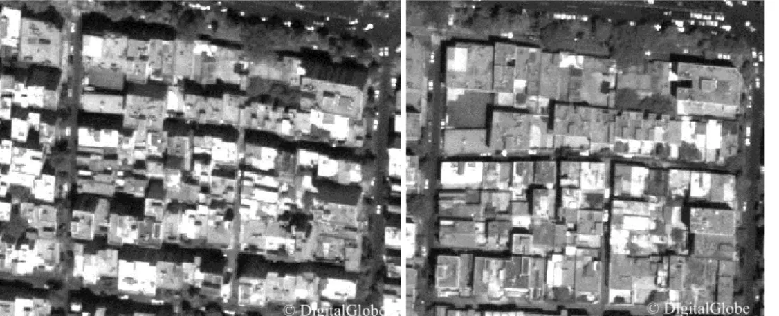
Figure 3. Stereo image acquisition in Kathmandu project. Left: viewing direction -31º, right: viewing direction +15º. The time difference between the two acquisitions is about 100 seconds.
Image processing and DSM generation
3.2.
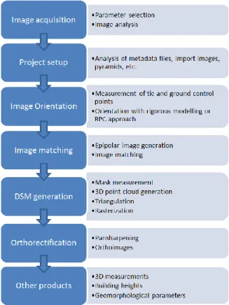
In this work we followed the classical photogrammetric workflow available in ERDAS Leica Photogrammetric Suite (LPS) environment (ERDAS LPS, 2011) for the processing of the stereo images and DSM generation (Figure 4).
© DigitalGlobe © DigitalGlobe
© DigitalGlobe © DigitalGlobe
Page 10 Figure 4. Photogrammetric workflow for 3D information extraction from stereo imagery.
The processing was applied separately to each dataset described in Table 2. On the orientation point of view, the geometric model for space borne push-broom sensors based on RPC was used. After importing the images with their RPC and metadata information and generating the pyramids, common tie points in two or more images were measured in order to ensure the relative orientation between the two images of the same stereo pair and between different stereo pairs that overlaps along or across the flight direction. The aim was to link the images and get a stable block; therefore a minimum of 5 tie points for each pair were measured manually by an operator. The general rule for tie point measurement is to select points on well-defined and fixed/stable features on the terrain (i.e. crossing lines, road signs, etc., Figure 5) and get a homogeneous distribution in the images scenes (Figure 27 to Figure 33 in Annex A). In total a minimum of 20 points for Guatemala City project and a maximum of 98 points for Teheran project were measured (Table 3).
Figure 5. Example of tie point selection in Panama City project.
Automatic tie point detection modules available in commercial software packages were tested as well, but none of them did produce accurate and reliable results, due to evident mismatches and point extraction on non-fixed or moving objects, like shadows or cars. Figure 27 to Figure 33 represent the projects, as set up in ERDAS LPS. Areas without tie point measurements were occluded by clouds, covered by water (i.e. rivers, lakes, sea) or image borders.
Page 11 The rigorous photogrammetric processing for the orientation of the images require ground control information to orient the block in a given absolute ground system. In our cases ground measurements were not available. Therefore we guaranteed that at least the relative orientation was correct through the analysis of its standard deviation (Table 3).
The DSM was generated in the ERDAS LPS module eATE (enhanced Automatic Terrain Extraction) with stereo image matching, which aims at finding dense and robust correspondences between stereo images and estimate their 3D coordinates in object space. The matching procedure in eATE is pyramid based, that is, it starts from a high image pyramid and terrain range is initialized with a global DEM generated with 3-second SRTM DEM; at each pyramid level, terrain range updated from matches on higher pyramid is used to limit search range at current pyramid, and matching results from current pyramid will be used to update terrain range at next lower pyramid. By this way, the ambiguity of terrain variation is reduced at each pyramid level and search range should be reduced as well and converge to a small value, which is a function of terrain slope, accuracy, and pixel size (Xu et al., 2008). Seed points were not added manually as mass point to help the matching and improve the DSM. Regions occluded by clouds were manually masked by an operator in image space and resulted with no-data value in the final DSM.
Taking into account the ground spatial resolution of the input images, the DSMs were generated with 2m grid spacing (about 4 times the pixel size of the panchromatic channels).
In case of projects with overlapping stereo pairs (i.e. Teheran, Kathmandu, Dakar, etc.), the DSM is computed separately for each stereo pair and then the single DSMs are merged using linear interpolation. Even if the blocks are relatively orientated, residuals propagate during DSM generation and produce small vertical steps between overlapping DSMs. In these cases, additional tie points are manually measured in the images in the critical area, the relative orientation recomputed and the DSM generated again. The final DSMs are then masked from water bodies (rivers, lakes, oceans, seas) using OpenStreetMap (OpenStreetMap, 2011) free datasets. Additional manual editing, like blunder filtering or manual measurement of seed (mass) points, was not applied to improve the quality of the DSMs.
Finally the most nadir images were ortho-rectified on the DSMs and ortho-images at 0.5m grid spacing were generated. Table 3 summarizes the area characteristics (size, height range) and the processing steps.
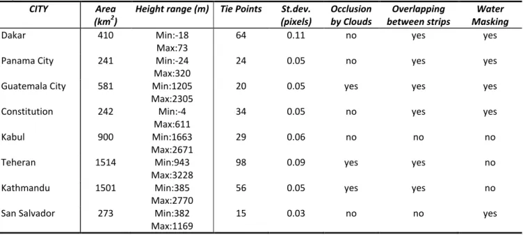
Table 3. Summary of terrain characteristics (area, min and max elevation above WGS84 ellipsoid) and processing for each city.
CITY Area
(km2)
Height range (m) Tie Points St.dev. (pixels) Occlusion by Clouds Overlapping between strips Water Masking Dakar 410 Min:-18 Max:73 64 0.11 no yes yes
Panama City 241 Min:-24
Max:320
24 0.05 no yes yes
Guatemala City 581 Min:1205 Max:2305
20 0.05 yes yes yes
Constitution 242 Min:-4 Max:611 34 0.05 no yes yes Kabul 900 Min:1663 Max:2671 29 0.06 no no no Teheran 1514 Min:943 Max:3228 98 0.09 yes yes no Kathmandu 1501 Min:385 Max:2770 56 0.05 yes yes no
San Salvador 273 Min:382
Max:1169
15 0.03 no no yes
DSM Quality analysis
3.3.
The objective of this analysis is to evaluate how the earth surface has been modeled in different scenarios, in relation to the characteristics of the source images (ground resolution, viewing angles, and radiometry) and terrain (cover, typology, texture). In general the DSMs were successfully generated from all datasets with both sensors (GE1 with processing level 2A and WV2 with processing levels 1B and 2A). The overviews of the DSMs extracted in the eight projects are reported from Figure 35 to Figure 42 in Annex B.
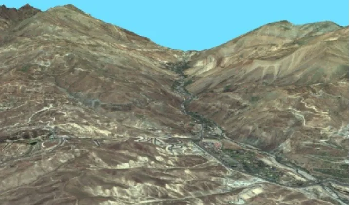
In mountain areas with large elevation difference, like Teheran, Kabul and Guatemala City, the shape of valleys and mountain sides and ridges is well modeled in the DSM (Figure 40). In comparison to SRTM, using VHR images it is possible to extract finer DSM and to filter the Digital Terrain Model (DTM) at higher grid space. This is confirmed by the comparison of the height profiles of the WV2 DTM and the SRTM in Teheran (Figure 7).
In rural areas, cultivated parcels can be distinguished, together with paths and lines of bushes and trees along their sides. In case of forest, the DSM clearly shows a different height with respect to adjacent cultivated areas or grass. It is even possible to distinguish roads and rivers crossing forests (Figure 8). In general rural areas are well modeled both in mountain, hilly and flat terrain.
Page 12 In urban areas building agglomerations, blocks with different heights, the road network, some infrastructures (i.e. stadium, bridges, etc.) and rivers are generally well outlined both in flat and hilly terrains (Figure 9). In residential and industrial areas it is possible to distinguish single buildings and lines of trees (Figure 10). In some cases the roof structures of large and complex buildings are modeled (Figure 36).
The quality of the DSMs in urban areas was also evaluated through the height profiles along transects. From the analysis of the profiles in Figure 12 and Figure 13 in residential and dense urban areas in Panama City, buildings are highlighted by the presence of peaks in the DSM and confirmed by visual interpretation in the corresponding orthophoto.
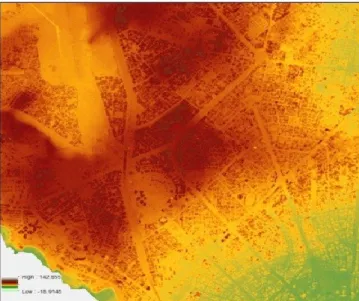
Figure 6. DSM of mountain area around Teheran. Figure 7. Height profile in WV2 DTM (blue) and SRTM (red) and zoom in the corresponding surface models (above: SRTM, below: WV2 DTM).
Figure 8. Left: DSM of Rural area in Constitucion. Right: Original image (panchromatic).
Figure 9. DSM of dense urban area on flat and hilly terrain in Dakar.
Page 13 Figure 10. DSM of residential and rural area on flat terrain
in Panama City. The black oval highlights a line of tree.
Figure 11. Left: DSM of Panama City Airport. Right: original image (pan sharpened).
Figure 12. Height profiles from DSM in residential urban area in Panama City along one transect. Heights are expresses in meters.
Figure 13. Height profiles from DSM (blue) and DTM (green) in dense urban area in Panama City along one transect. Heights are expresses in meters.
Failures in surface modeling can be caused by a number of factors, which are summarized in Table 4. The image absolute geo-location accuracy, which depends on the viewing angle, the processing level and terrain morphology, influence the estimation of the height in object space, and therefore the quality of the absolute geo-location of the final DSM and related products (DTM, orthophotos, 3D objects). The measurement of accurate and well distributed ground control points (GCPs) in the images would solve the problem, but this information is often not available. The accuracy of the relative orientation between two images forming a pair is crucial for the epipolar geometry and image matching, while the relative accuracy between overlapping stereo pairs is responsible of height steps in the final DSM (Figure 14). In both cases the relative orientation can be improved by manually measuring a sufficient number of common tie points between the images.
Low-textured and homogenous areas origin blunders in the DSM, as the automatic matching of the homologous points fails. This is typical in homogeneous land cover (i.e. bare soil, parking lots) and shadow areas and is caused by a combination of sun and satellite elevations and surface morphology (i.e. mountain faces). In Figure 15 building shadows, highlighted in the yellow ellipse, bring inaccuracies in the DSM. The use of a better initial DSM as initial approximation can help the matching procedures in these critical areas. If a DSM is not available, so-called seed points can be measured in stereo mode in the pairs and imported in the matching procedure as mass points. In addition, an ad-hoc radiometric processing can enhance details in low-textured regions and help the matching procedure.
Occlusions are generally present in urban areas and are due to tall buildings or trees, in combination with the acquisition viewing angles. In case of occlusions, corridors between buildings are not modeled correctly (Figure 16).
Objects moving during the acquisitions of the stereo images, like vehicles, lead to small blunders, as highlighted in the blue circles in Figure 15. They can be removed with manual editing or filtering.
Local blunders in correspondence of special radiometric effects, like spilling and saturation on roof faces due to the acquisition geometry and the surface type and inclination (i.e. roof faces in grass), may also occur.
© DigitalGlobe
Page 14 Figure 14. Height step (in the black rectangle) between the
DSMs obtained from two different stereo pairs (Dakar). Figure 15. Example of effects of shadows and moving objects in the DSM (Panama City). Above: pansharpened nadir scene; below: DSM
Figure 16. Example of corridor occlusion due to tall buildings; (a) and (b): stereo images; (c) resulting DSM (Dakar). Table 4. Summary of factors influencing the DSM quality.
Factor Cause/Dependency Effect in DSM Possible solution
Poor initial absolute geo-location accuracy
Viewing angles; Processing level; Terrain shape;
Height steps;
Poor final absolute geo location quality;
GCPs
Time interval between overlapping acquisitions
Large extent;
Swath width of VHR sensors;
Height steps in overlapping areas
Tie points measurements Differences in the images Moving objects (vehicles) Local blunders DSM editing;
Filtering;
Shadows Large viewing angle;
Sun inclination; Surface morphology;
Mismatches Radiometric
preprocessing Low texture areas Land covers (parking lots, bare
soil, etc.)
Mismatches Radiometric
preprocessing; Seed points; Spilling/saturation of roof Radiometry;
Sun and satellite elevation; Surface inclination; Surface material;
Local blunders Masking;
Occlusions in urban areas Convergence angle Local blunders Seed points
Height range Steep mountain;
Vertical steps;
Low details Seed points
Cloud cover Whether conditions Mismatches Masking
Water (lakes, sea) Bad quality DSM Masking
© DigitalGlobe
Page 15
4. 3D Information extraction
In the previous sections we demonstrated that it is possible to model large metropolitan area in detail using stereo images acquired by satellite VHR optical sensors. The DSMs allow for a series of automatic extraction of 3D information in order to prevent, monitor or simulate the major natural disasters in the world or assess any damages. Some common applications of DSMs include:
- Analyses of terrain geomorphology (aspect, roughness, slope, see an example in Figure 17) for geological studies (landslides or avalanche);
- Modeling of water flow and mass movement (Figure 18);
- Automatic buildings height extraction for volume and population estimation (Figure 19); - Baseline or relief map creation;
- Logistics, reconstruction and recovery, pipeline route planning;
- 3D visualization and realistic interactive fly-through navigation (Figure 20, Figure 21).
Figure 17. Slope in degrees of GE1 DSM (center) and SRTM (right) over Guatemala City and original image (left).
Figure 18. Flood simulation in North-East of Panama City
using WV2 DSM. Figure 19: 3D visualization of digital terrain model and buildings over Panama City. The color of the buildings corresponds to their height.
Figure 20: 3D visualization of digital surface model of Guatemala City from GE1 stereo pairs with texture from MS channels.
Figure 21: 3D visualization of digital surface model of Teheran from WV2 stereo pairs with texture from MS channels.
Page 16
Buildings height extraction
4.1.
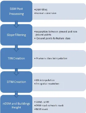
Among these applications, for automatic building height extraction the following methodology was adopted. The workflow is summarized in Figure 22. After a preliminary post-processing of the DSM (tiling and format conversion), the points on the ground are separated from those above ground in order to extract the digital model of the terrain (DTM). Since terrain slope is usually different from the slope seen between the ground and the tops of trees and buildings, this slope difference is used to separate ground and non-ground points. A point ( ) is classified as ground measurement if the maximum value ( ) of slopes between point ( ) within a given radius is less than predefined threshold s:
=
√( ) ( ) if < s
[1]
where is the slope between and . This filtering approach, based on Maximum Local Slope (MLS), is embedded in
ALDPAT 1.0 (Airborne LIDAR Data Processing and Analysis Tools) software (Zhang, K., Cui, Z., 2007). In general the algorithm performs well not only of flat areas but even on hilly areas densely populated (Figure 23). The points are located on roads and open areas (green-land, parking lot etc.).
Figure 22. Workflow of buildings height detection from DSM.
Figure 23. Ground points (in red) automatically extracted from Panama City DSM. Example on flat area (right) and hilly area (left).
The ground points are triangulated into a TIN (Triangulated Irregular Network) and then the TIN is interpolated and rasterized to get the DTM (Digital Terrain Model). By performing a pixel-by-pixel difference between the DSM and DTM, the so-called normalized DSM (nDSM) is obtained. The nDSM represents the height of all the objects present on the terrain. The objects include large buildings, dwellings, trees, stadium, streets, vehicles, goods container etc. As the purpose is to estimate the height of built-up structures, the next step is the masking of all objects that don’t belong to this category. In our study we experiment the use of NDVI and the road network available from OSM (Open Street Map, 2011) to remove
Page 17 trees and vegetation and roads and vehicles respectively. The NDVI was calculated on the orthorectified multispectral data. For each stereopair the images with viewing angle closer to nadir was used.
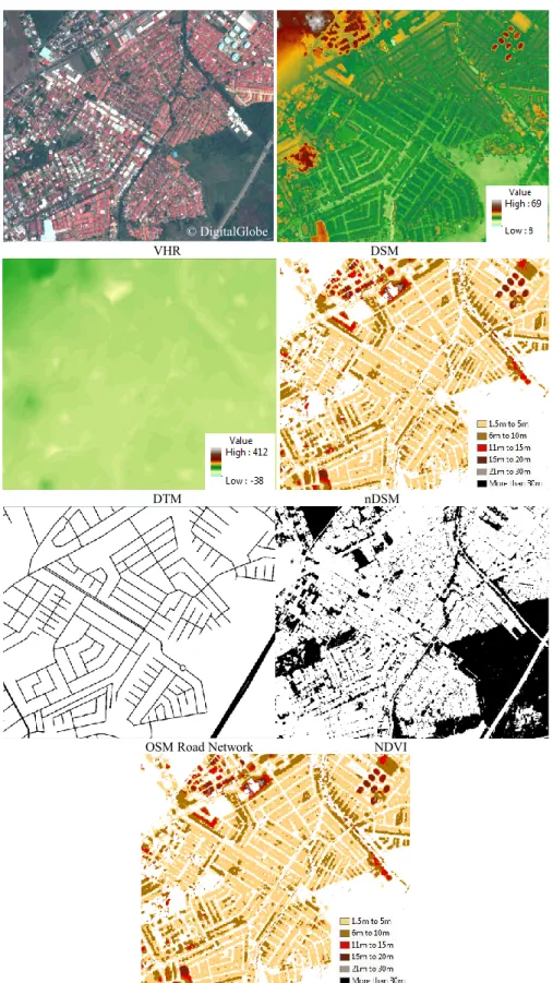
Today the OSM (a collaborative, open source project to develop free geographic data) is widely available basically all over the world and is very detailed in large cities. The lines of the road network were converted into merged polygons by assigning a size according the road type (highest values for motorway, lowest values for footway). Then the merged vector polygons were converted into raster format for the masking procedure. Figure 26 show an example of automatic building height extraction from the DSM on a subset in Panama City. The figure shows the original image, the DSM, DTM, nDSM, OSM and NDVI mask, final building heights. Other examples on Dakar (Figure 24) and Guatemala City (Figure 25) are shown.
The results show that the proposed methodology for automatic building height extraction is quite successful in complex scenarios with inhomogeneous terrain geomorphology (flat, hilly, mountain areas) and building topology (dense city centers, residential areas, and separated buildings). Due to lack of ground reference information it was not possible to evaluate quantitatively the correctness of the extracted height values. Anyway a visual analysis was conducted in a selection of areas with different characteristics in terms of building structure and terrain shape. As the completeness is concerned, building blocks are correctly defined in the final product. By comparing the extracted heights and the number of floors visible in the images, it resulted that the height range is corresponding to the reality. Remaining non-building objects mainly include image matching errors in homogeneous areas producing small blobs in the DSM and objects in bare soil or parking areas, that were not masked neither by the NDVI nor by the OSM.
Figure 24: Automatic building height extraction in Dakar from stereo images; results on a selected area. (left) pan-sharpened orthophoto (right) building height with legend.
Figure 25: Automatic building height extraction in Guatemala City from stereo images. (left) pan-sharpened orthophoto (right) building height with legend.
© GeoEye © GeoEye
Page 18 VHR DSM
DTM nDSM
OSM Road Network NDVI
Building heights
Figure 26: Automatic building height extraction in Panama City from stereo images.
5. Conclusions
This report discusses the quality of 3D surface modeling from VHR stereo images acquired from space borne platform. Thanks to the ability of last generation satellites, stereo images with along-track stereo viewing and ground sample distance below 1m can be acquired along one orbit path with a small time delay. Then standard photogrammetric procedures are followed to orient the images, generate epipolar images and extract the DSM with image matching procedures. In this report the DSMs were extracted from GeoEye1 stereo images over Dakar and Guatemala City and from WorldView-2
Page 19 stereo images over Panama City, Constitucion, Kabul, Teheran, Kathmandu and San Salvador using ERDAS LPS and eATE tools. Ground points were not available. The DSMs were not edited in post-processing, nor improved by measuring additional seed points to be used as mass points.
The analysis of the DSMs show that the surface quality is related to the acquisition parameters (i.e. satellite and sun elevation), the geometric processing (quality of initial orientation and availability of GCPs), the matching strategy (in our case, eATE tool in ERDAS LPS) and the terrain characteristics (i.e. morphology, height range, land cover, water, and cloud cover). On the acquisition point of view, the base-on-height ratio of the stereo acquisition, and consequently the convergence angles, is crucial for automatic DSM generation. On a theoretical point of view, the larger is the B/H ratio, better is the stereoscopy and the height estimation; on the other hand images acquired from very different viewing angles contain certain disadvantages. First of all, they show occlusions in urban areas occlusions due to buildings, therefore corridors between buildings cannot be modeled properly. In addition large angles produce longer shadows, and therefore low-texture homogeneous areas where image matching does not perform well. As the image processing is concerned, the quality of sensor geometric orientation determines the correctness of the estimated surface height in object space. In general ground control points are recommended to improve the image geo-location accuracy, but in case of remote areas or in emergency situation, this information cannot be recovered. Anyway it is recommended to guarantee the relative orientation between images composing a pairs and between pairs by manually measuring a sufficient number of well distributed common (tie) points in the images. In fact the inaccurate relative orientation of overlapping strips might cause height steps in the final DSM.
With regard to the sensor, the quality of GE1 and WV2 images is good and the very high spatial resolution allows detailed modeling of any terrain type. The availability of multispectral channels is favorable for future operation, like cloud and water masking, object identification.
The report demonstrated the potential of DSM from VHR imagery for the extraction of value-added 3D information, like building height, relevant for post-disaster and post-crisis needs assessment (PDNA) activities, monitoring and simulation of natural hazards.
6. References
Crowley, J.K., Hubbard, B.E., Mars, J.C., 2003. Analysis of potential debris flow source areas on Mount Shasta, California, by using airborne and satellite remote sensing data. Remote Sensing of Environment, 87(2-3), 345-358.
Deilami, K., Hashim, M., 2011. Very high resolution optical satellites for DEM generation: A review. European Journal of Scientific Research, 49(4), 542-554.
Delacourt, C., Allemand, P., Berthier, E., Raucoules, D., Casson, B., Grandjean, P., Pambrun, C., Varel, E., 2007. Remote-sensing techniques for analysing landslide kinematics: A review. Bulletin de la Societe Geologique de France, 178(2), 89-100.
ERDAS LPS, 2012. http://www.erdas.com/products/LPS/LPS/Details.aspx . Last visit: January 2012.
Fraser, C.S., Baltsavias, E., Gruen, A., 2002. Processing of Ikonos imagery for submetre 3D positioning and building extraction. ISPRS Journal of Photogrammetry & Remote Sensing, 56(3), 177-194.
Gamba, P., Houshmand, B., 2002. Joint analysis of SAR, LIDAR and aerial imagery for simultaneous extraction of land cover, DTM and 3D shape of buildings. International Journal of Remote Sensing, 23(20), 4439-4450.
Glaze, L.S., Baloga, S.M., 2003. DEM flow path prediction algorithm for geologic mass movements. Environmental and Engineering Geoscience, 9(3), 225-240.
Grodecki, J., Dial, G., 2003. Block adjustment of high-resolution satellite images described by Rational Polynomials. Photogrammetric Engineering and Remote Sensing, 69 (1), 59-68.
Gruber-Geymayer, B. C., Zebedin, L., Karner K., 2006. From pixels to buildings. Virtual Reality, May, 8-11.
Hu, D.-Y., Li, J., Zhao, W.-J., Peng, G.-X., 2008. Object-oriented landslide detection from remote sensing imageries with high resolution. Journal of Natural Disasters, Volume 17, Issue 6, Pages 42-46.
Jacobsen, K., 2011. Characteristics of very high resolution optical satellites for topographic mapping. International Archives of the Photogrammetry, Remote Sensing and Spatial Information Sciences, XXXVIII-4/W19, on CDROM. Kim, J., Kuwahara, Y., Kumar, M., 2011. A DEM-based evaluation of potential flood risk to enhance decision support system for safe evacuation. Natural Hazards, 59(3), 1561-1572.
Page 20 Li, Y., Zhu, L., Shimamura, H., Tachibanab, K., 2010. An integrated system on large scale building extraction from DSM. International Archives of the Photogrammetry, Remote Sensing and Spatial Information Sciences, XXXVIII, Part 3B, 35-39.
Liu, Q., Wang, L.-Q., 2011. Analysis and 3D visualization modeling of airborne laser scanning data. Proceedings of SPIE - The International Society for Optical Engineering, Volume 8192, 2011, Article number 81924J.
Narushige S., 2001. Urban models: Recent developments in the digital modelling of urban environments in threedimensions. GeoJournal 52, 263-269.
Nichol, J., Man, S.W., Shaker, A., 2006. Application of high-resolution satellite images to detailed landslide hazard assessment. Geomorphology 76 (1-2), pp. 68-75.
OpenStreetMap, 2011. URL: http://www.openstreetmap.org/ . Last visit: November 2011.
Pleiades, 2012. URL: http://events.eoportal.org/get_announce.php?an_id=8932. Last visit: January 2012.
Poli, D., 2007: A Rigorous Model for Spaceborne Linear Array Sensors. Photogrammetric Engineering & Remote Sensing, 73(2), 187-196.
Poli, D., Toutin, Th., 2012. Developments in geometric modelling for HR satellite push-broom sensors. The Photogrammetric Record, in press.
Stevens, N.F., Manville, V., Heron, D.W., 2003. The sensitivity of a volcanic flow model to digital elevation model accuracy: Experiments with digitised map contours and interferometric SAR at Ruapehu and Taranaki volcanoes, New Zealand. Journal of Volcanology and Geothermal Research, 119(1-4), 89-105.
Toutin, T., 2004. Review article: Geometric processing of remote sensing images: models, algorithms and methods. International Journal of Remote Sensing, 25(10), 1893-1924.
Toutin, Th., 2009. Fine spatial resolution optical sensors. Chapter 8 in SAGE Handbook of Remote Sensing (Eds. T. A. Warner, M. D. Nellis & G. M. Foody). SAGE, London, UK. 568 pages: 108–122.
Tralli, D.M. , Blom, R.G., Zlotnicki, V., Donnellan, A., Evans, D.L., 2005. Satellite remote sensing of earthquake, volcano, flood, landslide and coastal inundation hazards. ISPRS Journal of Photogrammetry and Remote Sensing, 59(4), 185-198. Xu, F. and Woodhouse, N. and Xu, Z. and Marr, D. and Yang, X. and Wang, Y., 2008. Blunder elimination techniques in adaptive automatic terrain extraction. ISPRS J., 29 (3), 21. p.1139-1148.
Zhang, K., Cui, Z., 2007. Airborne LIDAR Data Processing and Analysis Tools. Aldpat 1.0. Available at http://lidar.ihrc.fiu.edu/download/Doc/ALDPAT.pdf
Zischg, A., Schober, S., Sereinig, N., Rauter, M., Seymann, C., Goldschmidt, F., Bäk R., Schleicher, E., 2011. Monitoring the temporal development of natural hazard risks as a basis indicator for climate change adaptation. Journal of Natural Disasters, DOI: 10.1007/s11069-011-9927-0.
Page 21
Annex A. Project overview in ERDAS LPS working environment
Figure 27. Dakar project. Location of GeoEye stereo-pairs (in grey with white border) and manually measured tie points (red squares).
Figure 28. Panama City project. Location of WorldView-2 stereo-scenes and manually measured tie points (red squares).
Figure 29. Constitucion project. Location of WorldView-2 stereo-scenes and manually measured tie points (red squares).
Page 22 Figure 30. Guatemala City project. Location of GeoEye-1 stereo-scenes and manually measured tie points (red squares).
Page 23 Figure 32. Kathmandu project. Location of WorldView-2 stereo-scenes and manually measured tie points (red squares).
Figure 33. San Salvador project. Location of WorldView-2
stereo-scenes and manually measured tie points (red squares). Figure 34. Kabul project. Location of WorldView-2 stereo-scenes and manually measured tie points (red squares).
Page 24
Annex B. Overview of DSM
Page 25 Figure 36. Overview of DSM from WV2 stereo pairs over Panama City.
Page 26 Figure 38. Overview of DSM from WV2 stereo pairs over Constitucion.
Page 27 Figure 40. Overview of DSM from WV2 stereo pairs over Kabul.
Page 28 Figure 42. Overview of DSM from WV2 stereo pairs over San Salvador.
European Commission
EUR 25234 EN - Joint Research Centre – Institute for the Protection and Security of the Citizen
Title: Digital surface modelling and 3D information extraction from space borne very high resolution stereo pairs Authors: Poli, Caravaggi
2012 – 28 pp. – 21.0 x 29.7 cm
EUR – Scientific and Technical Research series – ISSN 1831-9424 (online), ISSN 1018-5593 (print)
ISBN 978-92-79-23177-3 doi:10.2788/15526 Abstract
This report discusses the potentials of VHR stereo imagery for automatic digital surface modelling (DSM) and 3D information extraction on large metropolitan cities. Stereo images acquired by GeoEye-1 on Dakar and Guatemala City and by WorldView-2 on Panama City, Constitucion (Chile), Kabul, Teheran, Kathmandu and San Salvador were processed following a rigorous photogrammetric approach. The work focusing on evaluating the quality of the DSMs in relation to the image and terrain characteristics and, among the possible DSM’s application, present a solution for buildings height estimation. The size of the datasets, the variety of case studies and the complexity of the scenarios allow to critically analyzing the potentials of VHR stereo imagery for 3D landscape modeling for natural hazards assessment.
How to obtain EU publications
Our priced publications are available from EU Bookshop (http://bookshop.europa.eu), where you can place an order with the sales agent of your choice.
The Publications Office has a worldwide network of sales agents. You can obtain their contact details by sending a fax to (352) 29 29-42758.
The mission of the JRC is to provide customer-driven scientific and technical support
for the conception, development, implementation and monitoring of EU policies. As a
service of the European Commission, the JRC functions as a reference centre of
science and technology for the Union. Close to the policy-making process, it serves
the common interest of the Member States, while being independent of special
interests, whether private or national.
LB -NA -25 23 4-EN -N