© 2019, IRJET | Impact Factor value: 7.211 | ISO 9001:2008 Certified Journal
| Page 3112
INDUSTRIAL ENERGY AUDIT
Simon Shiney
1, Akash Chauhan
2, Abhishek Singh
3, Arun Nair
4,
H.V. Rupareliya
51
Dept. of Electrical Engineering, ITM Universe Vadodara, Gujarat, India,
2Dept. of Electrical Engineering, ITM Universe Vadodara, Gujarat, India
3
Dept. of Electrical Engineering ITM Universe Vadodara, Gujarat, India
4Dept. of Electrical Engineering, ITM Universe Vadodara, Gujarat, India
5
Asst. professor, Dept. of Electrical Engineering, ITM Universe Vadodara, Gujarat, India
---***---Abstract
“Industrial Energy Audit was conducted at R.R. Industries, 815, GIDC, Makarpura Vadodara.
During this industrial audit, we monitored the entire production and process system through systematic analytical and statistical approach and technical calculations of both the industries.
This analysis and calculations helped us to identify and minimize the overall energy losses/waste in the entire industry and also, reduction in energy bills, without effecting the production and quality of the service. Consequently we were able to maximize the overall power factor to unity value and thus increase in the efficiency of the system through inclusion of power capacitors.”
Key words: System monitoring, loss Identification, analytical approach, Technical Calculation, energy losses, Cost reduction, improved Power Factor System Efficiency.
1.0.
INTRODUCTION
1.1.
ENERGY AUDIT :
Energy audit is the key to a systematic approach for decision making in the area of energy management. It attempts to balance the total energy input with its use, and serves to identify all energy streams in a facility. It quantifies energy usage according to its discrete functions.
Industrial energy audit is fundamental to a comprehensive energy management program and is defined in EC Act 2001 as follows:
“Energy Audit” means the verification, monitoring and analysis of use of energy including submission of technical report containing recommendation for improving energy efficiency with cost benefits analysis and an action plan to reduce energy consumption.
1.2.
OBJECTIVE :
The main Objective of this Energy Audit is to make “Divine Industries-Vadodara” an energy efficient industry through: Minimizing the energy losses/waste without affecting
the production and its quality Optimum utilization of the energy Reduction in energy utility bill / cost
To minimize the environment effects, if any.
1.3.
AUDIT METHODOLOGY:
Energy is one of the major inputs for the economic development of any country. In the case of the developing countries such as INDIA, the energy sector assumes a critical importance in view of the ever-increasing energy needs requiring huge investments to meet them.
In India, electrical energy consumption by industries is about 60% of the total energy consumption. The industrial development in the country is progressing at a fast pace due to the increase in the number of industries, the gap between demand and supply of electricity is also increasing day by day.
To minimize this gap, the best solution is to conduct is Energy Audit of all industries on regular bases.
The energy audit will determine energy wastage and losses, and provide techniques and ways to minimize the losses. The energy consumption techniques suggested by the energy audit will not only minimize the losses but also reduce monthly electricity bill.
Accordingly, it can be said that Energy Audit is the key to a systematic approach for decision-making in the area of energy management. It attempts to balance the total energy inputs with its use, and serves to identify all the energy streams in a facility.
Thus, we can conclude that Energy audit is the most significant step for implementation of any effective energy management program. It tries to answer how, where and how much energy is used in a system. It also provides an opportunity to look into energy use pattern and recommends way and mean of eliminating losses and improving the efficiency of the system.
1.4.
TYPES OF ENERGY AUDIT:
The type of energy audit to be performed depends on the types of industry, the depth to which final audit is needed, and the potential and magnitude of cost reduction desired. Thus energy audit can be classified into following types: 1. Preliminary Audit
© 2019, IRJET | Impact Factor value: 7.211 | ISO 9001:2008 Certified Journal
| Page 3113
3. Detailed audit1.5.
APPROACH TOWARDS THE ENERGY AUDIT:
Detailed energy audit is a comprehensive audit and results in a detailed energy project implementation plan for a facility, since its accounts for the energy use of all major equipment. It includes detailed energy cost saving calculation and project implementation costs.
One of the key elements in a detailed energy audit is the energy balance. This is based on an inventory of energy-using systems, assumption of current operating conditions, measurement and calculations of energy use.
Detailed energy auditing is carried out in three phases: 1. Pre Audit Phase
2. Audit Phase 3. Post Audit Phase
1.6.
PRE-AUDIT PHASE:
During the initial site visit following actions were taken: Discussion with the site’s senior management about the
aims of the energy audit.
Explain the purpose of the audit and indicate the kind of information needed during the facility tour. Obtain site drawing where available- plant/building
layout, steam distribution, compressed air distribution, electricity distribution etc.
Tour the site accompanied by site representative.
1.7. DETAILED AUDIT PHASE:
The information collected during the detailed audit includes:
Sources of energy supplies (e.g. electricity from the grid or self-generation).
Energy cost and tariff data.
Energy consumption by type of energy, by department, by major process equipment, by end-use.
Generation and distribution of site services. Process and material flow diagram.
Material balance data.(raw material, final product, recycled materials, use of scrap etc)
Review of ongoing energy management procedures and energy awareness training programs.
1.8.
POST AUDIT:
Data Collection: In preliminary data collection phase, exhaustive data collection was prepared using different methods such as observation, discussion with key persons, and measurements.
Information about the general electrical appliances was collected by observation and interviewing.
The Site drawing and details of building Lay-out and
Electricity Distribution system were collected. Electricity bill was collected from the personnel in-charge. Information was also collected on redundant / non-operational energy systems. The details of usage of the appliances were collected by interviewing key persons e.g. Electrician, caretaker (in case of departments) etc. and approximations and generalizations were done at places with lack of information.
Data analysis: Detailed analysis of data collected was performed.
The analysis of data was done in following manner: Review of Power Flow diagram, Evaluation of collected data, Reasons for the Variance of power flow between connected load and actual consumption was evaluated. Additionally, the database prepared was further scrutinized and the results are presented graphically, this helped to identify the areas with maximum energy saving potential.
On the basis of results of data analysis and observations, some steps, for reducing power consumption are provided herewith in this audit report. The recommended measures will NOT affect the present working conditions and at the same time substantial energy savings will arise.
Following steps are involved in this process:
The capital cost involved in recommended replacement of an appliance and/or process is estimated, the energy saving by the move is calculated in terms of price of energy per year. These two costs are compared to
calculate the capital cost recovery time which is defined as the Payback-Period by which the saving in energy bill balances the capital cost involved.
1.9.
INSTRUMENTS USED DURING DETAILED
AUDIT:
NO INSTRUMENTS NAME OF THE MAKE VALIDITY UP TO 1 Digital Tachometer ROTOTESLA JUNE-19
2 Tong tester/Clip on meter AMTEK DEC-19
3 Measuring tape of 100 meter 3M -
4 Lux meter AMTEK DEC-19
Table-01: Instruments used during energy audit
1.10.
TARRIF PLAN:
Rate - LTMD Plan ( 2018-2019)
This tariff is applicable to the services for the premises those are not covered in any other tariff categories and having aggregate load above 40 KW and up to 100 KW.
© 2019, IRJET | Impact Factor value: 7.211 | ISO 9001:2008 Certified Journal
| Page 3114
Fixed Charges + Energy Charges + Reactive Energy Charges,as shown below.
1. Fixed charges
1. For billing demand up to the
contract demand Charges
1. For first 40 KW of
billing demand Rs. 90/- per KW/ month 2. Next 20 KW of
billing demand Rs. 130/- per KW/ month 3. Above 60 KW of
billing demand Rs. 195/- per KW/ month 2. For billing demand in excess
of the contract demand Rs. 265/- per KW Plus
2. Energy charges
For the entire consumption during
the month 460 Paise per Unit
Plus
3. Reactive energy charges
For all the reactive Units (KVARH)
drawn during the month 10 Paise per KVARH
Billing demand:
The billing demand shall be highest of the following:
1. Eighty-five percent of the contract demand 2. Actual maximum demand registered during the
month 3. 15 KW
MINIMUM BILL :
Payment of demand charges every month based on the billing demand.
2.0. R.R FABRICATORS
2.1. DESCRIPTION OF THE INDUSTRY:
The energy audit was conducted at R.R. Fabrication Industries, Plot No. 814 & 815, GIDC, Makarpura Vadodara, INDIA. This Industry is Steel & Aluminum-Fabrication Industry which manufactures the equipment and accessories as per approved design data in Chemical, Petrochemical & Dairy Industries .Main products of this industries are CVT Tanks (400 KV, 765 KV), 800 KV Conductors and couplings ,Corona Ring (135 KV, 400 KV, 800 KV), Core supports, Top and bottom chambers of HV Bushings.
The total area of industry is 220 square meter and total staff strength 24. It has many types of equipment and heavy machinery like Shearing machine, lathe machine, milling machines, Power press, Welding sets, Cutters, Air
Conditioners, Drill machines, Sheet rounding machine, Hand Grinder (as shown in Table-05)
The Company’s primary source of power supply is from Madhya Gujarat Vij Company Limited (MGVCL) with Tariff Plan LMTD.
This plan is applicable to the services of the premises having aggregate load of above 40 KW and upto 100 KW.
2.2. GENERAL PLANT DETAILS:
Connected load details– (lighting):
N
o Lighting and Fans Type of
Mach ine Shop
Weldi ng Shop
Stores and Office
1 CFL Lights (85 W) 10 10 6
2 Air conditioner (1500 W) 0 0 2
3 accessories (150W) Computers and 0 0 3
4 Total Load 850 W 850 W 3960 W
Table-02: Connected lighting load
Total lighting Load including industrial Fans = 850+850+3960
= 5660 W =5.66 KW
Machinery and Equipment in the Industry:
No MACHINARY / NAME OF THE
EQUIPMENT QTY
CAPACITY OF THE INSTALLED EQUIPMENT IN
KW / KVA
1 OVERHEAD CRANE 1 10KW
2 TRANSFORMER TIG RECTIFIER 7 160 KVA (5), 130 KVA (2),
3 MOTOR FOR LATHE MACHINE 4 7.5KW(3), 10 KW
4 SHEARING MACHINE MOTOR FOR 2 2KW, 5KW
5 PRESS MACHINE KW MOTOR FOR 3 10KW, 15KW (2)
6 MOTOR FOR DRILLING MACHINE 2 2 KW (2)
7 GRINDING MACHINE MOTOR FOR 2 2KW,3KW
Table-03: List of machinery & equipment
© 2019, IRJET | Impact Factor value: 7.211 | ISO 9001:2008 Certified Journal
| Page 3115
Graph-01: Department wise energy consumptionEquipment layout in the industry:
Figure–01:Industries equipment layout
Single line diagram of electrical system:
Figure-02: Single line diagram of electrical system
Process flow diagram:
*
Figure-03: Industries process flow diagram
2.3. MEASUREMENT OF ELECTRICAL
PARAMETERS:
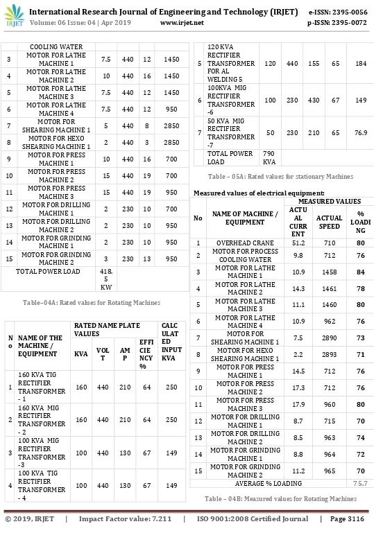
Rated values of electrical equipments:
No NAME OF MACHINE / EQUIPMENT
RATED NAME PLATE VALUES
KW VOLT MA P
RATED SPEED
1 OVERHEAD CRANE 10 440 53 700
© 2019, IRJET | Impact Factor value: 7.211 | ISO 9001:2008 Certified Journal
| Page 3116
COOLING WATER3 MOTOR FOR LATHE MACHINE 1 7.5 440 12 1450
4 MOTOR FOR LATHE MACHINE 2 10 440 16 1450
5 MOTOR FOR LATHE MACHINE 3 7.5 440 12 1450
6 MOTOR FOR LATHE MACHINE 4 7.5 440 12 950
7 SHEARING MACHINE 1 MOTOR FOR 5 440 8 2850
8 SHEARING MACHINE 1 MOTOR FOR HEXO 2 440 3 2850
9 MOTOR FOR PRESS MACHINE 1 10 440 16 700
10 MOTOR FOR PRESS MACHINE 2 15 440 19 700
11 MOTOR FOR PRESS MACHINE 3 15 440 19 950
12 MOTOR FOR DRILLING MACHINE 1 2 230 10 700
13 MOTOR FOR DRILLING MACHINE 2 2 230 10 950
14 MOTOR FOR GRINDING MACHINE 1 2 230 10 950
15 MOTOR FOR GRINDING MACHINE 2 3 230 13 950 TOTAL POWER LOAD 418.
5 KW
Table–04A: Rated values for Rotating Machines
N o
NAME OF THE MACHINE / EQUIPMENT
RATED NAME PLATE
VALUES CALCULAT
ED INPUT KVA KVA VOLT AMP
EFFI CIE NCY %
1
160 KVA TIG RECTIFIER TRANSFORMER - 1
160 440 210 64 250
2
160 KVA MIG RECTIFIER TRANSFORMER - 2
160 440 210 64 250
3
100 KVA MIG RECTIFIER TRANSFORMER -3
100 440 130 67 149
4
100 KVA TIG RECTIFIER TRANSFORMER - 4
100 440 130 67 149
5
120 KVA RECTIFIER TRANSFORMER FOR AL
WELDING 5
120 440 155 65 184
6
100KVA MIG RECTIFIER TRANSFORMER -6
100 230 430 67 149
7
50 KVA MIG RECTIFIER TRANSFORMER -7
50 230 210 65 76.9
TOTAL POWER
LOAD 790KVA
Table – 05A: Rated values for stationary Machines
Measured values of electrical equipment:
No NAME OF MACHINE / EQUIPMENT
MEASURED VALUES ACTU
AL CURR
ENT
ACTUAL SPEED
% LOADI
NG
1 OVERHEAD CRANE 51.2 710 80
2 MOTOR FOR PROCESS COOLING WATER 9.8 712 76
3 MOTOR FOR LATHE MACHINE 1 10.9 1458 84
4 MOTOR FOR LATHE MACHINE 2 14.3 1461 78
5 MOTOR FOR LATHE MACHINE 3 11.1 1460 80
6 MOTOR FOR LATHE MACHINE 4 10.9 962 76
7 SHEARING MACHINE 1 MOTOR FOR 7.5 2890 73
8 SHEARING MACHINE 1 MOTOR FOR HEXO 2.2 2893 71
9 MOTOR FOR PRESS MACHINE 1 14.5 712 76
10 MOTOR FOR PRESS MACHINE 2 17.3 712 76
11 MOTOR FOR PRESS MACHINE 3 17.9 960 80
12 MOTOR FOR DRILLING MACHINE 1 8.7 715 70
13 MOTOR FOR DRILLING MACHINE 2 8.5 963 74
14 MOTOR FOR GRINDING MACHINE 1 8.8 964 72
15 MOTOR FOR GRINDING MACHINE 2 11.2 965 70
[image:5.595.29.568.38.807.2]AVERAGE % LOADING 75.7
© 2019, IRJET | Impact Factor value: 7.211 | ISO 9001:2008 Certified Journal
| Page 3117
No NAME OF THE MACHINE / EQUIPMENT
MEASURED VALUES
AMP VOLT LOADI% NG 1 160 KVA TIG RECTIFIER TRANSFORMER- 1 205 432 61.2
2 160 KVA MIG RECTIFIER TRANSFORMER- 2 207 430 61.6
3 100 KVA MIG RECTIFIER TRANSFORMER-3 123 430 61.0
4 100 KVA TIG RECTIFIER TRANSFORMER- 4 121 439 61.7
5 120 KVA RECTIFIER TRANSFORMER FOR AL
WELDING 5 149 428 59.2
6 100KVA MIG RECTIFIER TRANSFORMER-6 418 228 63,8
7 50 KVA MIG RECTIFIER TRANSFORMER-7 199 232 60.5 TOTAL % LOADING: 60.8
Table–05B: Rated values for stationary Machines
Utility bill with pf:
Contract kw – 21 KW
N
O & Year Month PEA
K LOA
D (KW)
Reactiv e power (KVARh
)
UNIT CONSU
MED (KWh)
PF AmouBill nt
1 Dec-17 11.3 1196 1992 .85 15905
2 Jan-18 11 899 1714 .88 13944
3 Feb-18 10.5 1120 1594 .81 12841 4 Mar-18 11 1205 1870 .84 14872 5 Apr -18 11 1102 1972 .87 15334 6 May- 18 11.9 1410 2150 .83 15538 7 Jun- 18 12 1427 1937 .8 15458 8 Jul- 18 10.4 1329 1910 .82 14951 9 Aug- 18 10 1175 2117 .87 16288
AVERAGE
VALUES 11.02 1207 1917.3 .84 15014
Table–06: Utility bill with pf
Average power factor:
Graph-02: Average power factor
2.4. CALCULATIONS:
Reasons to Determine Motor Loading :
Most electric motors are designed to run at 50% to 100% of rated load. Maximum efficiency is usually near 75% of rated load. A motor’s efficiency tends to decrease dramatically below about 50% load. A motor is considered to be under-loaded when it is in the range where efficiency drops significantly with decreasing load.
As per NEMA design criteria, for motors up to 500 HP in size, % efficiency for various loads requires to be measured and plotted (graph) by the manufacturer. It is also required to have a full-load efficiency value stamped on the nameplate. From the universal “efficiency-Load” (Graph-07) of motors it can be seen that motor efficiencies generally peak at around 3/4 or 75% of load, and is almost identical to the efficiency at full load.
Graph–03: Efficiency and loading of motor
During this particular Energy Audit program, Percentage-Loading of rotating-machinery and static-machinery are calculated separately. For both type of above machines, a sample-calculation is separately provided for ease of understanding.
© 2019, IRJET | Impact Factor value: 7.211 | ISO 9001:2008 Certified Journal
| Page 3118
There are three methods to find % Loading of ElectricalMotors
1. Input power measurement 2. Line Current measurement 3. Shaft Slip-Speed Method
For this particular energy audit, we have adopted “Shaft Slip-Speed Method” to calculate % Loading of the equipment i.e. Motors
** (Here, Overhead Crane, at serial No.1 of Table-04 A, is
selected for below depicted sample calculation)% Loading of the Motor = Slip x 100 / Ss – Sr
Where Slip
= Difference between synchronous speed and actual measured speed of motor
Ss = Synchronous speed of the Motor
Sr = Rated Speed of the Motor (Name plate rating)
=
Synchronous speed – Measured speed x 100 / Synchronous speed – Rated Speed
= Operating slip / Full Load slip
= (750-710) x 100) / (750-700)
= 40 / 50 x 100
= 80 %
Percentage loading of all rotating equipment is calculated based on the above sample calculation and is recorded as shown in Table – 04B.
Calculation for stationary machinery :
** (Here, value of Table-05A, is selected for below depicted sample calculation)
Sample Calculation:
Rated Input
power in KVA = Rated output capacity of the equipment / Efficiency
= 160 / 0.64 = 250
Actual input KVA = Measured Measured Current Voltage x = 1.732 x 432 V x 205 A = 153 KVA
% Loading = Actual input KVA /
Rated input KVA = 153 x 100 / 250 = 61.2 % Loading
Calculation of power factor:
The required details, for power factor calculation is collected from MGVCL’s monthly utility bills as shown in Table - 06 The formula, for calculating Power factor, is as shown below:
Tan θ = KVARh / KWh
Where
Tan θ = Trigonometric Ratio of reactive power and Real power
KVARh = Reactive power hour
KWh = Real Power hour – Unit
Tan θ = 1196 / 1992 = 0.6
Θ = 30.98
Cos θ = 0.857
Power factor = 0.857
Calculation for sizing of power capacitor :
KVAR = KW x (Tan θ1 – Tan θ2)
Where
KVAR = Required capacity of the Power Capacitor in Kvar
KW = Contracted Active power KVA = Apparent Power
cosθ1 = Average Power factor of the system (Table - 09)
θ1 = Inv.Cosine of above average value
of power factor
Tan θ1 = Trigonometric ratio for present
power factor
Cos θ2 = Desired power factor
θ2 = Inv. Cosine of above desired value
of power factor
Tan θ2 = Trigonometric ratio for the desired
power factor KVAR = 21 X (1.55 – 0.044)
= 21 X 0.57 KVAR = 12.56 KVAR
© 2019, IRJET | Impact Factor value: 7.211 | ISO 9001:2008 Certified Journal
| Page 3119
Calculation for energy saving:Total Connected Load:
Lighting Loads + Rotating machine Load + Static Machine Load
= 5.66+ 418.5
= 424.16 KW
Ampere calculation:
Actual average current with existing Power Factor of 0.84
= Actual Load in Watts / 1.732 x 440 x0.84
= 42,416 / 640.9 = 66.18 Amp Average current
with desired Power Factor
of 0.999 = 56.22 Amp
KVA Calculation Apparent power in KVA for existing power factor 0.84
= Actual KW / Power factor
504.35 KVA Apparent power in KVA with
desired power factor 0.999 = Actual KW / Power factor 424.58 KVA
Difference in KVA = 504.35 – 424.58 79.76 KVA
KW Calculation:
Real power in KW for existing
power factor 0.84 = P.F X KVA = 424.15KW Real power in KW for desired
power factor 0.999 = P.F X KVA = 420.33 KW Difference in KW = 424.15 - 420.33 =
3.8 KW
KVAR calculations:
Reactive power in KVAr for
existing power factor = KVA X sin θ = 272.87 KVAr Reactive power in KVAr
for desired power factor = KVA X sin θ = 59.89 KVAr Difference in KVAr = 272.87 – 59.89 =
212.97 KVAr
Total Energy Saving:
KVA - SAVING PER
MONTH = 79.76 HOURS/DAY KVA X X 26 9 DAYS/MONTH
= 18663.84 KVA KW - SAVING PER
MONTHING = 3.8 KW X 9 HOURS/DAY X 26 DAYS/MONTH
= 889.2 KWh KVAR - SAVING PER
MONTH = 141 HOURS/DAY KVAR X X 26 9 DAYS/MONTH
= 49,834.98 KVARh
COST BENEFIT WITH INCLUSION POWER CAPCITOR
1
BENEFIT IN ENERGY CHARGE
889.2 KWh X 4.60 RS
Rs. 4090.32 MONTHLY
SAVING. Rs. 49083.84 ANNUAL SAVING
PLUS
2
BENEFIT IN REACTIVE ENERGY CHARGES
49834.98 KVARh X 10 PAISE Rs. 4983.49 MONTHLY SAVING Rs. 59801.97 ANNUAL SAVING
3 TOTAL SAVING
Rs. 9073.81 MONTHLY SAVING
Rs. 108,885.81 ANNUAL SAVING
Table-07: Cost benefits with inclusion of power capacitor
2.5. INVESTMENT
:
NO
DESCRIPTION OF ITEM
UNIT COST (IN RS) QUA NTI TY TOTAL PRICE
1. AUTOMATIC LIGHTING CIRCUIT 3,500 1 3,500
2 13 KVAR CAPACITOR 1,000 13 13,000
TOTAL INVESTMENT 16,500
GRAND TOTAL : TOTAL INVESTMENT PLUS 12 % INTEREST RATE
18,480
Table-08: Total Investment required.
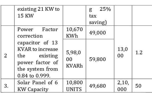
2.6. ANNUAL ENERGY SAVING AND PAYBACK
PERIOD
:
N O
ENERGY SAVING RECOMMENDATI ON ANNU AL ENERG Y SAVIN G ANNUAL COST SAVING IN Rs. CAPI TAL INV EST IN Rs, SIMP LE PAYB ACK PERI OD IN MON THS
1 Reduce existing Contract-the
Demand from 72 KW
8,100
© 2019, IRJET | Impact Factor value: 7.211 | ISO 9001:2008 Certified Journal
| Page 3120
existing 21 KW to15 KW g 25% tax
saving)
2
Power Factor correction capacitor of 13 KVAR to increase the existing power factor of the system from 0.84 to 0.999.
10,670
KWh 49,000
13,0 00 1.2 5,98,0
00
KVARh 59,800
[image:9.595.29.296.90.258.2]3. Solar Panel of 6 KW Capacity 10,800 UNITS 49,680 2,10,000 50
Table–09: Annual cost saving and payback period
2.7. AUDIT OBSERVATIONS
Primary observations :
1. It has been observed that the operators fail to turn OFF the equipment when not in use.
2. Aluminum sheets and scraps are not properly discarded so there may be a danger of accident. 3. It is observed that there remains a certain amount of
smoke build-up inside the welding shop.
4. A.C ventilation needs to be checked regularly to safe guard from certain on-going spraying / painting activity.
Observation - Energy consumption and Power Factor:
The monthly electricity bill for the year 2018, showing energy consumption (KWh) is tabulated in Table-09. From this table it is observed that the energy consumed varies from a maximum value of 2150 KWh Units in the month of May 2018 to a minimum value of 1594 KWh Units in the month of February 2018.
The variation of power factor is also is tabulated in Table-09. It is observed that the power factor value varies between 0.8 to 0.87. These values of the power factor are found to be less than the desired value of 0.999.
Observation - Percentage Loading of Equipment
% Loading of of motors
Table 08A shows the Performance of different rotating machines in terms of its % loading.
From this table it can be seen that:
All motors, are working at average %loading of 75.7%. So we can say that all motors are loaded nearly or above the ¾ loads i.e. nearly 75 %. So we can say that they operate very near to maximum efficiency.
% Loading of Welding-Rectifiers
It is observed that most of the welding rectifier are working above 60% loading. This loading is sufficiently good for welding machine, since the output of the welding machine is nearly short-circuited.
2.8. RECOMMENDATION FOR ENCON
No cost measures:
1. We strongly recommend the management to change their existing contract demand of 21 KW to 15KW with immediate effect.
2. Cleaning of A.C ventilation should be included in PREVENTIVE MAINTENANCE schedule.
3. Aluminum scrap sheets should be collected time to time and store in a proper place. They may be re-used or sold to earn certain amount of money.
4. Replace Compact Fluorescent Lamps (CFL's) by LED lights.
NOTE:
It should be noted that In energy Conservation in lighting system, good lighting is required to improve the quality of work, to reduce human’s / worker’s fatigue, to reduce accidents, to protect his eyes and nervous system. It improves production, and quality of products / work. Optimum use of natural light, whenever the orientation of a building permits, day lighting has to be used in combination with electric lighting.
The maxim use of sunlight can be utilized by means of transparent roof sheets.
For lighting system, the advantage of sunlight should be availed by leaving lights off during the day.
Additionally, It is strongly suggested to create awareness among the workers about the important of ENERGY SAVING AND CONSERVATION.
Low c os t me asu re s:
1. The welding shop should be provided with adequate size of energy efficient exhaust fans (minimum 2 nos.) to remove smoke.
2. Install Timer-based automatic lighting circuit.
Medium cost measure:
1, Based on calculation, as shown in Para 5.4.6, we strongly recommend the Management of R.R. Fab Industries to install a Power Factor correction capacitor of 13 KVAR rating (rounding off to 15 KVAR) which would increase the existing power factor of 0.84 to 0.99.
Energy Conservation can also be achieved by using Automatic power factor controller (APFC).
© 2019, IRJET | Impact Factor value: 7.211 | ISO 9001:2008 Certified Journal
| Page 3121
lighting load of 5.78 KW (as shown in table-06)with installationof 5KW of solar energy(solar panel). Each 1KW panel would produce 5 units per day. Total annual saving by installing this 5KW panel would be @ Rs. 41,000. The payback period would be around 4 years.
3.
CONCLUSIONS:
Through conducting this energy audit in the industry, we achieved every set objective and if, the following proposed recommendations are accepted and implemented by the management of the industry, then they would certainly get mentioned benefits within the specified pay-back period.
Recommendations:
1. Reduction in the Contract Demand in KW :
This is basically a No-Cost measure. If this measure is implemented, then the monetary benefit would be of @ Rs 8100/- annually.
2. Inclusion of 13 KVAR sized Power Capacitor:
Inclusion of above recommended power capacitor would help to achieve near Unit power Factor which has direct effect on Active and Reactive power of the system.
The investment involved in implementing this recommendation is @ Rs 13,000/- only however if implemented, this would generate a benefit of @ Rs 108,800/- annually.
The calculated minimal Pay-Back period would be 1 months 5 days.
3. 5-KW Renewable solar panel system Installation:
We strongly recommend for installation of 6 KW renewable Solar panel system, which would assist to supply energy to the overall Lighting system of 5.66 KW.
This installation would certainly minimize the monthly energy bill.
The total investment of 5 KW solar panel installation would be @ Rs 240,000/-.
The Pay-Back period would be @ 4 years and 2 months (50 months).
ACKNOWLEDGEMENT :
WE, place on record our sincere thanks to Mr. Hardik Rupareliya, Assistant Professor ITM Universe, Mr. S C Patel, Energy Manager (BEE) and Mr. Shiney Abraham (Lead-Auditor-IRCA) for vesting their confidence in us and providing the paramount guidance to carry out this project.
REFERENCES
[1] Bureau of Energy Efficiency
[2] https://www.sgs.com/en/sustainability/environment/e
nergy-services/energy-audits-and-management/energy-audit
[3] https://ieeexplore.ieee.org/document/4250239/ [4] https://www.google.com/url?sa=t&source=web&rct=j&
url=https://www.pnnl.gov/main/publications/external
/technical_reports/PNNL-20956.pdf&ved=2ahUKEwihuIa8zrfcAhXWfisKHYyYB0s QFjAKegQIAhAB&usg=AOvVaw1iOzkgvh7z9tefTJigyrwA
BIOGRAPHIES :
Mr. Simon Shiney was born in Vadodara, Gujarat. Currently pursuing his Bachelor in Engineering in Electrical Engineering from ITM UNIVERSE, Vadodara.
Mr. Akash Chauhan was born in Vadodara, Gujarat. Currently pursuing his Bachelor in Engineering in Electrical Engineering from ITM UNIVERSE, Vadodara.
Mr. Abhishek Singh was born in Vadodara, Gujarat. Currently pursuing his Bachelor in Engineering in Electrical Engineering from ITM UNIVERSE, Vadodara.
Mr. Arun Nair was born in Vadodara, Gujarat. Currently pursuing his Bachelor in Engineering in Electrical Engineering from ITM UNIVERSE, Vadodara.