warwick.ac.uk/lib-publications
Original citation:
Hu, Gaofeng, Gao, Weiguo, Chen, Ye, Zhang, Dawei, Tian, Yanling, Qi, Xiangyang and Zhang, Hongjie (2018) An experimental study on the rotational accuracy of variable preload spindle-bearing system. Advances in Mechanical Engineering, 10 (5). pp. 1-14.
doi:10.1177/1687814018776171
Permanent WRAP URL:
http://wrap.warwick.ac.uk/102733
Copyright and reuse:
The Warwick Research Archive Portal (WRAP) makes this work of researchers of the University of Warwick available open access under the following conditions.
This article is made available under the Creative Commons Attribution 4.0 International license (CC BY 4.0) and may be reused according to the conditions of the license. For more details see: http://creativecommons.org/licenses/by/4.0/
A note on versions:
The version presented in WRAP is the published version, or, version of record, and may be cited as it appears here.
Advances in Mechanical Engineering
2018, Vol. 10(5) 1–14
ÓThe Author(s) 2018 DOI: 10.1177/1687814018776171 journals.sagepub.com/home/ade
An experimental study on the
rotational accuracy of variable preload
spindle-bearing system
Gaofeng Hu
1, Weiguo Gao
1, Ye Chen
1, Dawei Zhang
1, Yanling Tian
1,2,
Xiangyang Qi
3and Hongjie Zhang
3Abstract
The rotational performance of the spindle-bearing system has critical influence upon the geometric shape and surface roughness of the machined parts. The effects of preload and preload method on the rotational performance of the spindle-bearing system is explored experimentally to reveal the role of preload and preload method in spindle rotational performances under different speeds. A test rig on which both the rigid preload and elastic preload can be realized, equipped with variable preload spindle-bearing system, is developed. Based on the mechanical model, the relationship of the axial preload and negative axial clearance of the spindle-bearing system is provided. Rotating sensitive radial error motion tests are conducted for evaluating synchronous and asynchronous radial errors of the variable preload spindle-bearing system under different rotating speeds and preload methods. The change regularity of synchronous and asyn-chronous radial errors with preloads under different rotating speeds are given. The results show that the preload plays an important role on the rotational performance of spindle-bearing system. The rigid preload is more efficient in achiev-ing better rotational performance than elastic preload under the same rotatachiev-ing speed. Furthermore, this article signifi-cantly guides the preload designing and assembling of the new spindle-bearing system.
Keywords
Rotational performance, variable preload spindle-bearing system, rigid preload, elastic preload, synchronous radial error, asynchronous radial error
Date received: 10 January 2018; accepted: 17 April 2018
Handling Editor: Jan Torgersen
Introduction
The rotational performance of the spindle-bearing sys-tem has critical influence upon the geometric shape and surface roughness of the machined parts and becomes an important technical indicator when evaluating the dynamic performance of the spindle.1,2 In order to select an optimum preload of the spindle-bearing sys-tem in spindle assembling process, good understanding of the change regularity of rotational performances with preload and rotating speeds under different pre-load methods is essential.
In recent years, many studies have been conducted to study the effects of the preload on the performance
1
Key Laboratory of Mechanism Theory and Equipment Design of Ministry of Education, Tianjin University, Tianjin, China 2
School of Engineering, The University of Warwick, Coventry, UK 3
School of Mechanical Engineering, Tianjin Polytechnic University, Tianjin, China
Corresponding authors:
Weiguo Gao, Key Laboratory of Mechanism Theory and Equipment Design of Ministry of Education, Tianjin University, Tianjin 300350, China. Email: [email protected]
Dawei Zhang, Key Laboratory of Mechanism Theory and Equipment Design of Ministry of Education, Tianjin University, Tianjin 300350, China. Email: [email protected]
of the spindle-bearing system. Literature review shows that some researchers have investigated the effect of the preload on the dynamic characteristics of the spindle system,3–9and found that high preload of the bearing can enhance the stiffness and the natural frequency of the spindle. Other works have focused on the effects of bearing preload on the thermal behaviors of the spin-dle.10–16
The existing preload methods of the spindle-bearing system are categorized into two types according to the stiffness of the preload mechanism: rigid preload and elastic preload.17,18 Rigid preload (Fixed position pre-load), is applied by inducing a constant relative displa-cement between the inner and outer rings by using match-ground bearing sets or two ground spacers whose heights are different. Elastic preload is exerted by utilizing springs.19 However, the preload is exerted in spindle assembling process and the value of the pre-load cannot be re-adjusted after the spindle assembling process is completed. Therefore, many studies have been conducted to study the variable preload technol-ogy. The researches are mainly focused on the design of the preload mechanism20–22 and the determination of the optimum preload.11The application of variable pre-load mechanism in practice is uncommon because the variable preload technology is still in research stage.3
Yang et al.23 and Chen et al.24 developed an instrument to analyze the rotational accuracy of high-precision rolling element bearing. A pneumatic mechanism was utilized to adjust the preload. The rota-tional accuracy of a single bearing rather than the spindle-bearing system has been measured. Kim and Kim2investigated the effect of the preload on the rota-tional accuracy under different speeds. Kim et al.25 investigated the effect of the preload on the run-out of the spindle under different speeds. However, they did not consider the rigid preload case. Li et al.26 investi-gated the non-uniform preload on the rotational per-formance and provided a new compensation method to spindle rotational error.
It is worth noting that in these studies, few investiga-tions have been performed on sensitivity of rotational performance to different preloads and preload meth-ods. Therefore, it is essential to develop a preload mea-surement and adjustment system, on which rigid preload and elastic preload can be realized, as well as radial error measurement system so as to study the effects of preload on the rotational accuracy of the spindle-bearing system.
In this article, the effects of the assembling preload (initial preload or preload after assembly) on the rota-tional performances of the spindle-bearing system under different preload methods is investigated experi-mentally. In the ‘‘Variable preload spindle-bearing sys-tem’’ section, a variable spindle-bearing system with preload adjustment mechanism is proposed for
investigating different preload methods. Based on the mechanical model of spindle-bearing system, the rela-tionship of the axial preload and negative axial clear-ance of the spindle-bearing system is provided. The centrifugal force induced preload and the radial stiff-ness of the spindle-bearing system are calculated and analyzed. In the ‘‘Test method and measurement sys-tem’’ section, the preload measurement and adjustment system, as well as radial error measurement system are established. In the section ‘‘Experimental analysis,’’ a series of experiments are carried out for evaluating the radial errors of the spindle-bearing system. The effects of preload and preload method, as well as the rotating speed on the synchronous and asynchronous radial errors are analyzed. The change regularity of rotational performance with preloads under different rotating speeds are given. The final section gives some conclu-sions and suggestions for future research.
Variable preload spindle-bearing system
Concept and operation principles
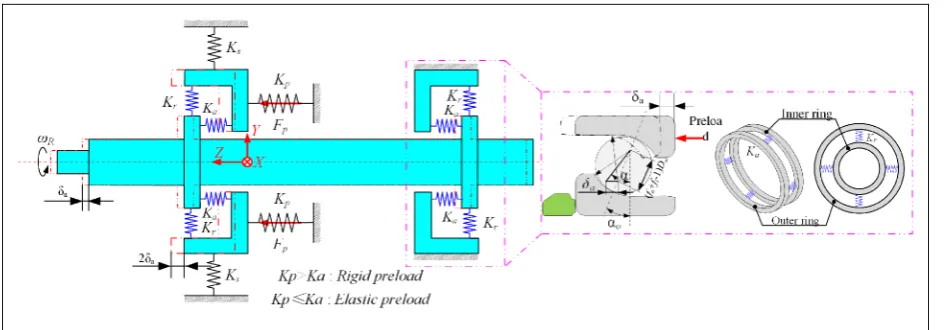
In order to investigate the effects of variable preload and preload method on the rotational performance of spindle-bearing system, a variable preload test rig is developed. The detailed structures are shown in Figure 1. A high-precision motorized spindle is utilized to drive the variable preload test rig. The rated speed of the test rig is 8000 r/min. Rigid and elastic preload mechanisms are installed on the test rig.
The rotor is supported by two pairs of universal combination angular contact bearings. The front and rear bearings are double tandem arrangement, but in opposite direction (double O configurations). The rear sleeve can slide along theZ-axis freely, while the front sleeve is fixed. All the bearings are restrained along the radial direction. Three preload springs are distributed evenly along the circumferential circle of the rear sleeve. The adjustable fine thread bolt (7, 8, 9), preload spring, and force sensor are mounted in series. The output forces of the preload springs, denoted byFp1,Fp2, and
Fp3, are evenly distributed on the rear sleeve and can be
adjusted by the adjustable fine thread bolt 7, 8, 9. There are six adjustable fine thread screws and three high-precision capacitive displacement sensors installed on rear sleeve.
in Z-axis direction, both front and rear bearings are preloaded. The actual preload (preload in rotating state) under elastic preload method depends on the spring stiffness. If the axial stiffness of the bearing is much larger than the preload spring, the actual preload of the spindle-bearing system can be treated as a con-stant value.
The elastic preload spindle-bearing system can be switched to the rigid preload spindle-bearing system easily. The rigid preload method is implemented by screwing the six adjustable fine thread screws circularly. The negative axial clearance of four bearings, denoted by D1, D2, and D3, respectively, can be measured/
adjusted by the capacitive displacement sensors/adjus-table fine thread screw 1, 2, 3. The relationship between the preload and negative axial clearance can be achieved by the elastic preload method. The position of the rear sleeve can be adjusted and fixed by utilizing the adjustable fine thread screws 4, 5, and 6. It is noted
that, fixing the rear sleeve on the test bed at the desired position is an iterative process.
IfFp1, Fp2, andFp3orD1, D2, andD3are equal to
each other, the preloads are evenly and uniformly dis-tributed on the rear sleeve, whileFp1, Fp2, and Fp3or
D1, D2, and D3 are not equal to each other, the
pre-loads are applied non-uniformly to the rear sleeve. In this article, we only investigate the uniform preload. The variable preload control technology lays the foun-dation for investigating the non-uniform preload.
Mechanical model of the variable spindle-bearing
system
[image:4.595.69.537.72.260.2] [image:4.595.71.546.310.475.2]The mechanical model of the variable spindle-bearing system is illustrated in Figure 2. In mechanical domain, the preload spring can be treated as an elastic compo-nent with constant stiffness, denoted bykp. The bearing can be simplified as a nonlinear spring according to the Figure 1. The detailed structure of the variable preload test rig.
Hertz contact theory, whose stiffness can be equivalent to axial stiffness and radial stiffness.27The contact stiff-ness Ks between the rear sleeve and the base can be derived by literature.28
According to the measured axial clearances, three types of bearings with different preloads (EL, L, M) are provided by NSK, Inc. In engineering application, in order to change preload, we could adjust the axial clearance by a spacer. Since the bearing preload and structure parameter are the important factors for the spindle-bearing system, the bearing parameters and the recommended preload values are specifically tabulated in Table 1. The recommended preload value represents that on one single ball bearing only. As the spindle sys-tem is installed with double O configuration form, the recommended preload value is twice as the preload for the single bearing according to the NSK bearing handbook.
The relationship between the preload and negative axial clear-ance in static state. The axial displacement of the rear sleeve 2darepresents the negative axial clearance of four bearing combinations wheredais the relative motion of the inner ring with respect to the outer ring of the bear-ing. The bearing stiffness is a series stiffness combina-tion of the ball/inner-raceway contact load and ball/ outer-raceway contact load. That is29
Kn=
1 1 Ki 1:5 + 1 Ko 1:5 0 B @ 1 C A 1:5
ð1Þ
whereKiandKoare the load-displacement coefficients for ball and outer/inner raceways, respectively. Kiand
Kocan be obtained by equations (2) and (4).
Based on the Hertz contact theory,29the inner ring contact stiffnessKiis
Ki=
2pkE 3Fð Þe
ffiffiffiffiffiffiffiffiffiffiffiffiffiffiffiffiffiffiffiffiffiffiffiffi 2Eð Þe Fð Þ e Pri s
ð2Þ
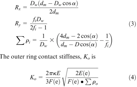
whereRxandRyare the parameters that depend on the ball and inner ring, Pri is the curvature sum of the inner raceway and ball
Rx=
DwðdmDwcosaÞ
2dm
Ry=
fiDw
2fi1
X
ri= 1
Dw
3 4dm2cosð Þa
dmDcosð Þa
1
fi
ð3Þ
The outer ring contact stiffness,Kois
Ko=
2pkE 3Fð Þe
ffiffiffiffiffiffiffiffiffiffiffiffiffiffiffiffiffiffiffiffiffiffiffiffi 2Eð Þe Fð Þ e Pro s
ð4Þ
whereRxandRyare the parameters that depend on the ball and outer ring, Pro is the curvature sum of the outer raceway and ball
Rx=
foDw
2fo1
Ry=
Dwðdm+DwcosaÞ
2dm
X
ro= 1
Dw
3 4dm+2cosð Þa
dm+Dcosð Þa
1
fo
ð5Þ
E (in equations (2) and (4)) is the equivalent elastic modulus of the Hertz contact and can be obtained by equation (6)
E= E1E2
1(u1)2
E2+ 1(u2)2
E1 !
ð6Þ
whereE1andE2are the elastic modulus of the ring and
ceramic rolling element, respectively, andu1andu2are
the Poisson’s ratios of the ring and ceramic rolling ele-ment, respectively.
Based on the linear regressive equation of Brewe and Hamrock29
k=1:0339 Ry Rx
0:636
Eð Þe =1:003+0:5968R y
Rx
Fð Þe =1:5277+0:6023ln Ry Rx
[image:5.595.311.534.200.342.2]ð7Þ
Table 1. Parameters and recommended preload value of the selected bearing (Model: NSK 65BNR10H SUELP4Y).
d(mm) D(mm) ao(°) Z Dw(mm) fi fo dm(mm) Recommended preload value (N)
EL L M
65 100 18 28 7.144 0.5403 0.5403 81.65 50 280 413
d: inner diameter;D: outer diameter;ao: initial contact angle;Z: number of rolling element;Dw: diameter of rolling element;fo: outer groove
curvature radius coefficient;fi: inner groove curvature radius coefficient;dm: pitch diameter;EL: extreme light preload;L: light preload;M: middle
Substituting equation (1) in equation (7), one can get the relationship of the axial preload and axial displace-ment using Newton–Raphson method
3Fp
ZKnððfi+fo1ÞDwÞ1:5
= sina cosa8 cosa 1
1:5
da=
Dwðfi+fo1Þsinðaa8Þ
cosa 8 > > > < > > > :
ð8Þ
where
Fp1=Fp2=Fp3
Fp=
Fp1+Fp2+Fp3
3 8
<
: ð8Þ
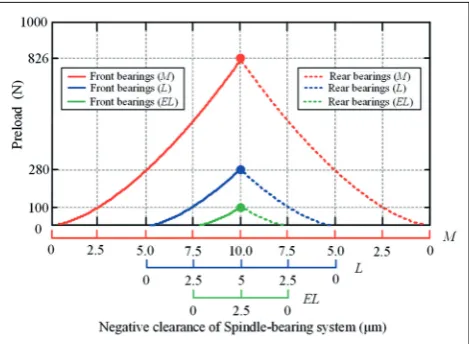
Figure 3 illustrates the relationship of the axial pre-load and negative axial clearance of the spindle-bearing system under different preloads. When the negative axial clearance of the rear sleeve is set to 10mm in rigid preload method, the equivalent preload value in elastic preload method is 280 N. Similarly, when the negative axial clearance of the rear sleeve is set to 20mm, the equivalent preload value is 826 N.
The radial stiffness of the spindle-bearing system in rotational state. The rotational accuracy of the spindle-bearing system is an important technical indicator when evalu-ating the dynamic performance of the spindle.1,2From the dynamic point of view, the radial stiffness of the bearing plays an important role in the rotational accu-racy of the spindle-bearing system. The bearing preload has a great influence on spindle stiffness. In order to calculate the radial stiffness of the bearing in rotational state, actual preload of the bearing is essential. As to elastic preload, the thermally induced preload and cen-trifugal induced preload can be absorbed by the preload
[image:6.595.63.298.71.243.2]spring as the axial stiffness of the bearing is much larger than the spring. The preload in rotational state and the assembling preload are nearly equal to each other. However, as to rigid preload, because the axial stiffness of the bearing is smaller than the preload mechanism, the preload in rotational state depends on the assem-bling preload, the centrifugal induced preload, and the thermally induced preload. In rotational state, the ther-mally induced preload and the centrifugal force induced preload exist at the same time. Thermally induced pre-loads have not been considered and calculated, since they involve more complicated issues and the rotating speed in this study is not very high. The effect of ther-mally induced preload on the running accuracy will be studied in future.
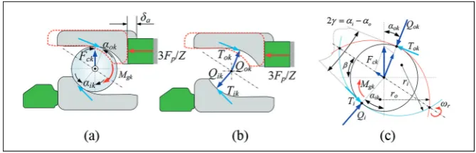
Figure 4 shows the positions of the ball center and raceway groove curvature centers. Figure 5 shows the axial loads equilibrium graph of a single angular con-tact ball bearing. There are a gyroscopic moment and two loads that act on the bearing in rotational state. 3Fp/Z is the axial preload on a single ball,Fck is the centrifugal force. The summed bearing load on a single ball in rotational state will be the summation of 3Fp/
Z, andFck, if the thermal effect is excluded. The equili-brium of the loads acting on thekth ball in the horizon-tal and vertical directions can be stated as29
QiksinaikQoksinaok
Mgk
Dw
licosaiklocosaok
ð Þ=0
QikcosaikQokcosaok
Mgk
Dw
lisinaiklosinaok
ð Þ+Fck=0
8 > > < > > :
ð9Þ
The normal contact force at the inner and outer race-way can be stated as
Qik=Kikdik1:5
Qok=Kokdok1:5
ð10Þ
where Qi(o)k is the contact load between the inner (outer) ring and thekth ball,Ki(o)kis the coefficient of the load-displacement between the inner (outer) ring and thekthball.di(o)kis the contact deformation of the inner (outer) ring. As to outer raceway control,li= 0,
Tik= 0; lo= 2, Tok= 2Mg / Dw. The gyroscopic moment Mgk and centrifugal force Fck acting on the
kth ball can be described by as follows29
Mgk=Jvrvbsinb
Fck=12mdmvb2
vr=vDbdwm 1+Dwdcosm a8
vb=v2R 1Dwcosdm a8
b= tan1 sinao
cosao+Dwdm
8 > > > > > > > > > < > > > > > > > > > :
[image:6.595.63.297.345.471.2]ð11Þ
wherevRis the rotational speed of the rotor,vr is the angular velocity of the ball, andvbis the angular velo-city of the bearing cage.
The axial distance between the position of outer and inner raceway groove curvature centers is
A1k=ðfo+fi1ÞDwsina8+da
A2k=ðfo+fi1ÞDwcosa8 ð
12Þ
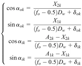
New variablesX1andX2are introduced as seen from
Figure 4(b)
cosaok=
X2k
fo0:5
ð ÞDw+dok
sinaok=
X1k
fo0:5
ð ÞDw+dok
cosaik=
A2kX2k
fo0:5
ð ÞDw+dik
sinaik=
A1kX1k
fo0:5
ð ÞDw+dik
8 > > > > > > > > > > > < > > > > > > > > > > > :
ð13Þ
Using the Pythagorean theorem, it can be seen from Figure 4(b) that
A1kX1k
ð Þ2+ðA2kX2kÞ2½ðfi0:5ÞDw+dik2=0 X1k2+X2k2½ðfo0:5ÞDw+dok2=0
ð14Þ
3Fp
X
k=Z k=1
KikðA1kX1kÞdik1:5liDMwgkðA2kX2kÞ fi0:5
ð ÞDw+dik
!
=0
ð15Þ
Equation (15) is highly coupled and nonlinear, and can be solved by using Newton–Raphson numerical method. As to rigid preload, assume that the stiffness of
Kpis infinite and the negative axial clearancedais given, the actual rigid preloadFacan be calculated. As to elas-tic preload, if the preload is constant, the actual nega-tive axial clearance daa can be calculated. The actual preload of the spindle-bearing system under different speeds is illustrated in Figure 6(a).
The bearing radial stiffness under preload can be cal-culated by equation (16)
Kr=
1 J K½ tJT+Fdaada
acotao
ð16Þ
where
J= cos½ u1 cosu2 cosuZ ð17Þ
½Kt=
Kr1
Kr2
. . .
KrZ
2 6 6 6 4
3 7 7 7 5
Z3Z
[image:7.595.70.515.71.327.2] [image:7.595.100.234.521.628.2]ð18Þ
whereukis the angular position of thekth ball in the global coordinate as shown in Figure 4(a) andFais the actual preload of the bearing. As to rigid preload,daais the axial displacement under preload Fa in the static state anddais the initial negative axial clearance under preload 3Fp. As to elastic preload,daais the axial displa-cement under preload 3Fpin the rotational state andda is the initial negative axial clearance under preload 3Fp. The actual radial stiffness of the spindle-bearing system under different speeds is illustrated in Figure 6(b).
As shown in Figure 6(a), as to elastic preload, the actual preload is a constant value (equal to the assem-bling preload). However, as to rigid preload, the actual preload increases with the speed due to the centrifugal induced preload. Figure 6(b) shows the change regular-ity of radial stiffness with rotational speed under differ-ent preloads and preload methods. It can be seen that with the speed increases, the radial stiffness of the bear-ing drops in both preload methods. The reason is that the bearing stiffness is a series stiffness combination
(ball/inner ring contact stiffness and ball/outer ring contact stiffness). The contact stiffness between ball and outer ring increases while the contact stiffness between ball and inner ring decreases due to the centri-fugal force. Therefore, the total radial stiffness decreases with the rotational speed continuously. The drop phenomenon is more significant under elastic load method as spindle-bearing system with elastic pre-load allows the bearing rings to change their relative axial position as reported in Cao et al.9In other words, compared to elastic preload, the rigid preload is more efficient in achieving higher radial stiffness.
Test method and measurement system
Test method of the rotational accuracy
[image:8.595.136.471.71.179.2]Conventional measurement methods of spindle rotating accuracy include static method, single-direction method, and two-direction method.30 In this article, Figure 5. Axial loads equilibrium graph of a single angular contact ball bearing: (a) loads acting on bearing, (b) equilibrium of bearing rings, and (c) equilibrium of bearing ball.
[image:8.595.84.529.240.455.2]rotation is in the sensitive direction of the rotor, so direction method is utilized. The schematic of two-direction measurement method is shown in Figure 7. Two orthogonal capacitive displacement sensors are applied to inspect the radial error motion. The displa-cement signals acquired by the capacitive displadispla-cement sensor A and B, areDX(u)andDY(u), respectively.
DX(u) =dx+Dex+DRx ð19Þ
DY(u) =dy+Dey+DRy ð20Þ
wheredxanddyare the rotor error motion inXandY
direction,DexandDeyare installation eccentricity error
in X and Y direction, and DRx and DRy are cylinder
error of the rotor. The installation eccentricity error can be eliminated by filtering first harmonic compo-nent. In order to facilitate the analysis, cylinder error of the rotor can be omitted due to its high precision.
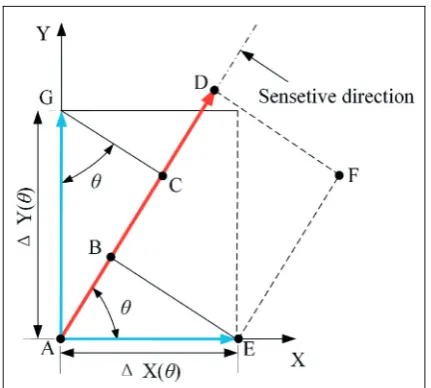
The vector diagram of rotational accuracy for sensi-tive direction is shown in Figure 8.
According to the geometric relationship of the vec-tor diagram, the following equations can be obtained apparently
AB
!
=DX(u)cos (u) ð21Þ
AC
!
=DY(u)sin (u) =EF! ð22Þ
AD
!
=AB!+EF!=DX(u)cos (u) +DY(u)sin (u) ð23Þ
The radial error motion at angular positionucan be calculated by equation (24)
rð Þu =r0+DXð Þ u cosu+DYð Þ u sinu ð24Þ
where r0 is the value of the basic circle radius set by
alignment of the displacement sensors and the rotor. By adjusting the value of r0, the plot of the error motion
would be easy to identify, without affecting error motion value.
Measurement system of rotational performance
Figure 9 shows the monolithic preload measurement and adjustment system as well as radial error measure-ment system used for measuring the rotational accuracy of the test rig. The system consists of NI DAQ Card (USB-6356), force sensors (HBM-C9C from HBM, Inc.) including the amplifier, and capacitive displace-ment sensors (C8-2.0 Lion, Inc.) including the ampli-fier. All the devices are placed on a vibration-isolated table. Table 2 shows the measuring conditions in this experiment. The experiment is conducted under the middle preload (both rigid preload method and elastic preload method) continuously when the temperature is stable, so the thermal effect on the rotational accuracy is neglected.
Experimental analysis
Preload–negative axial clearance experiments for
variable spindle-bearing system
[image:9.595.59.274.68.307.2]The comparisons of the measured and simulated val-ues of the preload and negative axial clearance are
Figure 7. Schematic of two-direction measurement method.
[image:9.595.308.524.69.263.2]shown in Figure 10. It can be seen that, with the pre-load increases from 0 to 826 N, the negative axial clearance of the rear sleeve and rotor increase with a same tendency. For a given preload value, the nega-tive axial clearance of the rear sleeve is approximately twice as large as that of the rotor. The simulated val-ues are in good accordance with the experimental results. However,D1is 3mm larger than D2 andD3.
[image:10.595.139.470.70.379.2]The reason is that the actual bearing preload is distributed non-uniformly along the circumference of the outer bearing ring due to the gravity of the rotor.
[image:10.595.62.553.447.568.2]Figure 9. Photograph of the measurement system.
Table 2. Measuring conditions.
Bearing configuration Double O configuration
Bearing type NSK 65BNR10H SUELP4Y
Preload EL L M
Rigid preload 2.5mm 5mm 10mm
Elastic preload 100 N 280 N 826 N
Preload spring stiffness 100 N/mm
Rotational speed (r/min) 100, 750, 1500, 2250, 3000, 3750, 4500, 5250, 6000 Sample rate (Hz) 5000–15,000
Length of samples 60 revolutions Environment temperature 20°C61°C
[image:10.595.310.547.589.716.2]Evaluation of the radial error for variable
spindle-bearing system
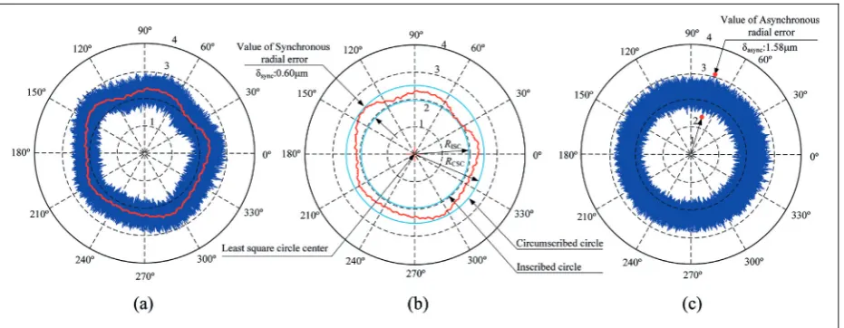
In accordance with ANSI/ASME standard or ISO standard,31,32 total error motion polar plots can be plotted by using the data of displacement sensors as shown in Figure 11(a). Least square circle (LSC) eva-luation method is used to assess the synchronous radial error of the rotor. Actually, the calculation of synchro-nous error motion value is a process of nonlinear least square fitting. The calculation process is expressed in equation (25)
X
R(u)syncRLSC
2
= min ð25Þ
where uis the corresponding angular position of sam-pling andRLSCis the radius of LSC.
From the LSC center, a circumscribed circle and an inscribed circle can be obtained. The radial width between the circumscribed circle and inscribed circle is determined as the synchronous radial error of the spindle-bearing system as illustrated in Figure 11(b).
Synchronous error motion value dsync can be calcu-lated by equation (26)
dsync=RCSCRISC ð26Þ
where RCSC and RISC are the radius of the circum-scribed circle and the incircum-scribed circle, respectively.
Figure 11(c) shows the asynchronous error motion polar plots. Asynchronous error motion value is the maximum scaled width of asynchronous error motion polar plot, measured along a radial line through the polar chart center at any angular position around cir-cumference. Asynchronous error motion valuedsynccan be calculated as follows
dasyn= rð Þumaxrð Þu min
max ð27Þ
wherer(u)minandr(u)maxare the maximum and the min-imum values of the total error motion from the same angular positionu.
Results and discussion
To demonstrate the effects of the preload and preload method on the rotational performance, a series of mea-surements are performed under different speeds and axial preloads.
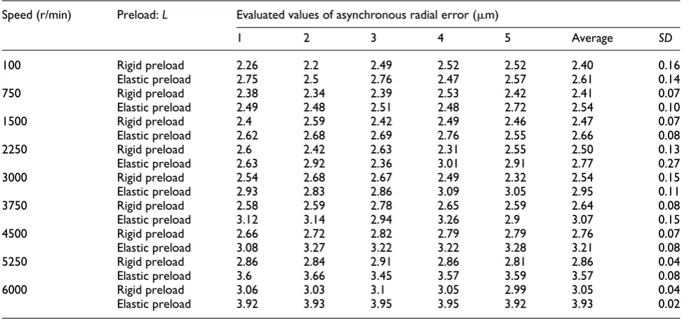
In order to reduce the random errors and increase the reliability and repeatability of the measurement, the radial error motion values were measured five times at the same speed and preload. Tables 3 and 4 show the evaluation of synchronous and asynchronous radial error motion values at different speeds under the light preload (280 N/10mm) in both rigid preload method and elastic preload method. The average values and standard deviations (SD) of five measurements at each speed are also listed in Tables 3 and 4.
Tables 5 and 6 show the synchronous and asynchro-nous error motions values for the variable preload test rig under various spindle speeds and axial preloads.
[image:11.595.60.526.70.251.2]increases, the synchronous and asynchronous radial errors decrease obviously at a given rotational speed.
Synchronous radial error, which represents the repe-titive behavior of spindle-bearing system, is caused due to the roundness of the ball and the raceway of the bearing. Asynchronous radial error is caused by imper-fections and defects in the balls and raceway of the bearing.30From the dynamics point of view, the radial stiffness plays a significant role to reduce the vibration levels of the rotor and consequently results in better
[image:12.595.62.552.86.314.2]rotational accuracy. The general trend of synchronous/ asynchronous radial errors is contrary to the trend of radial stiffness under different preloads and rotational speeds. With the increase of rotating speed, the radial stiffness of the spindle-bearing system decreases gradu-ally for a given preload/negative axial clearance. This decreases the capability of the bearing to reduce rotor vibration levels. That is why the synchronous and asyn-chronous errors increase with the increases of rota-tional speed. When the rotating speed is given, the Table 3. Evaluated values for synchronous radial error at different spindle speeds (Preload:L).
Speed (r/min) Preload:L Evaluated values of synchronous radial error (mm)
1 2 3 4 5 Average SD
100 Rigid preload 1.00 1.12 1.05 1.18 1.14 1.10 0.07
Elastic preload 1.17 1.24 1.21 1.12 1.22 1.19 0.05
750 Rigid preload 1.03 1.05 1.06 1.13 1.11 1.08 0.04
Elastic preload 1.24 1.13 1.12 1.17 1.14 1.16 0.05
1500 Rigid preload 1.19 1.11 1.07 1.13 1.10 1.12 0.04
Elastic preload 1.23 1.13 1.21 1.16 1.17 1.18 0.04
2250 Rigid preload 1.09 1.08 1.14 1.07 1.03 1.08 0.04
Elastic preload 1.18 1.14 1.25 1.28 1.19 1.21 0.06
3000 Rigid preload 1.14 1.19 1.10 1.19 1.05 1.13 0.06
Elastic preload 1.23 1.16 1.17 1.25 1.29 1.22 0.05
3750 Rigid preload 1.16 1.07 1.07 1.13 1.15 1.12 0.04
Elastic preload 1.30 1.26 1.24 1.16 1.23 1.24 0.05
4500 Rigid preload 1.11 1.13 1.23 1.11 1.14 1.14 0.05
Elastic preload 1.36 1.33 1.33 1.36 1.34 1.34 0.02
5250 Rigid preload 1.23 1.23 1.21 1.26 1.20 1.23 0.02
Elastic preload 1.42 1.40 1.44 1.42 1.38 1.41 0.02
6000 Rigid preload 1.25 1.31 1.30 1.26 1.30 1.28 0.03
Elastic preload 1.55 1.52 1.55 1.58 1.56 1.55 0.02
Table 4. Evaluated values for asynchronous radial error at different spindle speeds (Preload:L).
Speed (r/min) Preload:L Evaluated values of asynchronous radial error (mm)
1 2 3 4 5 Average SD
100 Rigid preload 2.26 2.2 2.49 2.52 2.52 2.40 0.16
Elastic preload 2.75 2.5 2.76 2.47 2.57 2.61 0.14
750 Rigid preload 2.38 2.34 2.39 2.53 2.42 2.41 0.07
Elastic preload 2.49 2.48 2.51 2.48 2.72 2.54 0.10
1500 Rigid preload 2.4 2.59 2.42 2.49 2.46 2.47 0.07
Elastic preload 2.62 2.68 2.69 2.76 2.55 2.66 0.08
2250 Rigid preload 2.6 2.42 2.63 2.31 2.55 2.50 0.13
Elastic preload 2.63 2.92 2.36 3.01 2.91 2.77 0.27
3000 Rigid preload 2.54 2.68 2.67 2.49 2.32 2.54 0.15
Elastic preload 2.93 2.83 2.86 3.09 3.05 2.95 0.11
3750 Rigid preload 2.58 2.59 2.78 2.65 2.59 2.64 0.08
Elastic preload 3.12 3.14 2.94 3.26 2.9 3.07 0.15
4500 Rigid preload 2.66 2.72 2.82 2.79 2.79 2.76 0.07
Elastic preload 3.08 3.27 3.22 3.22 3.28 3.21 0.08
5250 Rigid preload 2.86 2.84 2.91 2.86 2.81 2.86 0.04
Elastic preload 3.6 3.66 3.45 3.57 3.59 3.57 0.08
6000 Rigid preload 3.06 3.03 3.1 3.05 2.99 3.05 0.04
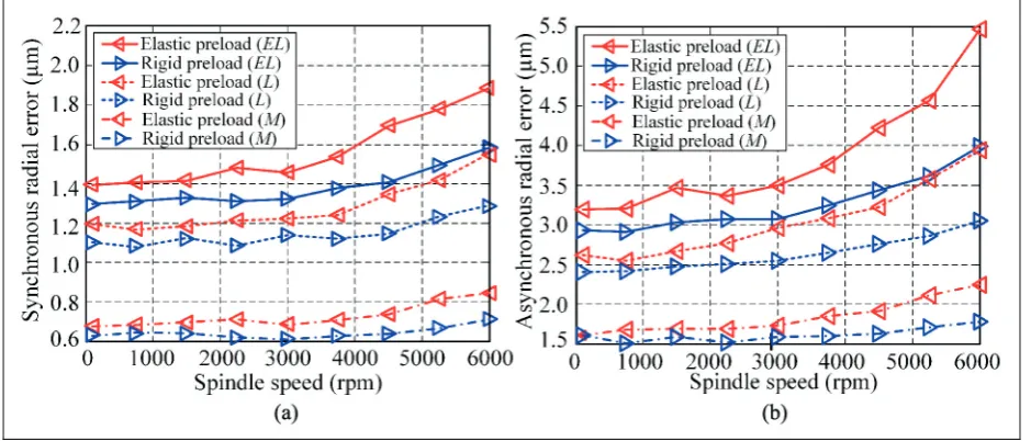
[image:12.595.61.552.361.589.2]Table 5. Evaluated values for synchronous radial error under different spindle speeds and preloads (mm).
Speed (r/min) Evaluated values of synchronous radial error (mm)
Rigid preload Elastic preload Rigid preload Elastic preload Rigid preload Elastic preload
2.5mm 100 N 5mm 280 N 10mm 826 N
100 1.29 1.39 1.10 1.19 0.62 0.67
750 1.31 1.40 1.08 1.16 0.64 0.68
1500 1.33 1.41 1.12 1.18 0.64 0.69
2250 1.31 1.48 1.08 1.21 0.61 0.71
3000 1.32 1.45 1.13 1.22 0.60 0.68
3750 1.37 1.54 1.12 1.24 0.62 0.70
4500 1.41 1.69 1.14 1.34 0.63 0.73
5250 1.49 1.77 1.23 1.41 0.66 0.81
[image:13.595.49.535.285.432.2]6000 1.58 1.88 1.28 1.55 0.71 0.84
Table 6. Evaluated values for asynchronous radial error under different spindle speeds and preloads (mm).
Speed (r/min) Evaluated values of asynchronous radial error (mm)
Rigid preload Elastic preload Rigid preload Elastic preload Rigid preload Elastic preload
2.5mm 140 N 5mm 280 N 10mm 826 N
100 2.92 3.19 2.40 2.61 1.60 1.60
750 2.90 3.20 2.41 2.54 1.50 1.68
1500 3.03 3.46 2.47 2.66 1.59 1.68
2250 3.06 3.36 2.50 2.77 1.51 1.68
3000 3.07 3.49 2.54 2.95 1.58 1.72
3750 3.24 3.76 2.64 3.07 1.59 1.84
4500 3.43 4.22 2.76 3.21 1.62 1.91
5250 3.61 4.57 2.86 3.57 1.70 2.11
6000 3.98 5.45 3.05 3.93 1.77 2.24
[image:13.595.58.528.481.682.2]radial stiffness of the spindle-bearing system increases due to the Hertz contact area between the ball and the raceway being flattened by the increase of preload. Consequently, it leads to the reduction in the evaluated value of synchronous and asynchronous radial errors of the spindle-bearing system.
Attention should be drawn to the deviation value of the synchronous/asynchronous errors between the rigid preload method and elastic preload method. The syn-chronous/asynchronous errors of the spindle-bearing system in rigid preload method is smaller than that in elastic preload method for a given speed. As mentioned above, the rigid preload is more efficient in achieving higher radial stiffness in rotational state due to the cen-trifugal induced preload. For a given rotational speed, the radial stiffness in rigid preload method is larger than in elastic preload method. This is the reason why the synchronous/asynchronous radial errors in elastic preload method is larger than that in rigid preload method. With the speed increase, the deviation value of radial stiffness between the two preload methods is becoming gradually larger due to the spindle-bearing system with elastic preload allowing the bearing rings to change their relative axial position. Consequently, the deviation value of the synchronous and asynchro-nous errors between the two preload methods is becom-ing gradually larger.
Conclusion
This article mainly investigates the effect of preloads and preload methods on the rotational performance of the spindle-bearing system by means of experiment. A new test rig equipped with variable preload spindle-bearing system is developed. Not only rigid preload but also elastic preload can be realized on the test rig. The mechanical model of the variable preload spindle-bearing system under different preload methods is established. Based on the model, the correspondence between preload and negative axial clearance of the spindle-bearing system is provided. The radial stiffness of the spindle-bearing system in rotational state are cal-culated and analyzed. The preload measurement and adjustment system, as well as radial error measurement system are established. Based on the measurement sys-tem, rotating sensitive radial error motion tests are car-ried out for evaluating the radial errors of the spindle-bearing system. The synchronous and asynchronous radial errors are found to be greatly affected by the pre-load. With the preload increases, the synchronous and asynchronous radial errors decrease obviously at the same speed. In addition, as the rotational speed increases, the deviation value of the synchronous and asynchronous errors between the two preload methods is becoming gradually larger, and the rigid preload has
a certain advantage in achieving better rotational performance.
In order to find the optimum preload of the spindle-bearing system under different speeds, the effects of the temperature on the rotational performance in both pre-load methods will be further studied in the future. It is also important to develop a variable preload mechan-ism to control the preload or negative axial clearance in alternating machining process actively.
Acknowledgements
The authors thank the reviewers for their comments.
Declaration of conflicting interests
The author(s) declared no potential conflicts of interest with respect to the research, authorship, and/or publication of this article.
Funding
The author(s) disclosed receipt of the following financial sup-port for the research, authorship, and/or publication of this article: The authors gratefully acknowledge the supports of the fund of national nature science foundation of China No. 51775375, National science and technology major project of China under Grant No. 2017ZX04021001, the fund of nature science foundation of Tianjin No. 17JCZDJC40300.
ORCID iD
Dawei Zhang https://orcid.org/0000-0003-4895-7189
References
1. Marsh ER.Precision spindle metrology. Lancaster:
DES-tech Publications, 2009, pp.1–38.
2. Kim K and Kim SS. Effect of preload on running
accu-racy of spindle.Int J Mach Tool Manu1989; 29: 99–105.
3. Cao HR, Zhang XW and Chen XF. The concept and
progress of intelligent spindles: a review.Int J Mach Tool
Manu2017; 112: 21–52.
4. Ozturk E, Kumar U, Turner S, et al. Investigation of spindle bearing preload on dynamics and stability limit
in milling.CIRP Ann: Manuf Techn2012; 61: 343–346.
5. Alfares MA and Elsharkawy AA. Effects of axial pre-loading of angular contact ball bearings on the dynamics
of a grinding machine spindle system. J Mater Process
Tech2003; 136: 48–59.
6. Cao YZ and Altintas Y. A general method for the
mod-eling of spindle-bearing systems.J Mech Des: T ASME
2004; 126: 1089–1104.
7. Spiewak SA and Nickel T. Vibration based preload
esti-mation in machine tool spindles.Int J Mach Tool Manu
2001; 41: 567–588.
8. Lin CW, Lin YK and Chu CH. Dynamic models and design of spindle-bearing systems of machine tools: a
review.Int J Precis Eng Man2013; 14: 513–521.
different preload mechanisms. Int J Adv Manuf Tech 2011; 57: 871–883.
10. Tu JF and Stein JL. Active thermal preload regulation
for machine tool spindles with rolling element bearings.J
Manuf Sci E: T ASME1996; 118: 499–505.
11. Jiang SY and Mao HB. Investigation of variable
opti-mum preload for a machine tool spindle.Int J Mach Tool
Manu2010; 50: 19–28.
12. Lin CW, Tu JF and Kamman J. An integrated thermo-mechanical-dynamic model to characterize motorized machine tool spindles during very high speed rotation. Int J Mach Tool Manu2003; 43: 1035–1050.
13. Chen J-S and Chen K-W. Bearing load analysis and
con-trol of a motorized high speed spindle.Int J Mach Tool
Manu2005; 45: 1487–1493.
14. Jeng YR and Gao CC. Investigation of the ball-bearing
temperature rise under an oil–air lubrication system.Proc
IMechE Part J: J Engineering Tribology 2001; 215: 139–148.
15. Bossmanns B and Tu JF. A thermal model for high speed
motorized spindles. Int J Mach Tool Manu 1999; 39:
1345–1366.
16. Li HQ and Shin YC. Analysis of bearing configuration effects on high speed spindles using an integrated
dynamic thermo-mechanical spindle model. Int J Mach
Tool Manu2004; 44: 347–364.
17. NSK. Catalogue-Super precision bearings. 2007C-9.
China. NSK, 2011, pp.152–153.
18. Zhang YF, Li XH, Hong J, et al. Investigation of multi-ple spindle characteristics under non-uniform bearing
preload.Adv Mech Eng2017; 9: 1–11.
19. Hwang KY and Lee CM. A review on the preload tech-nology of the rolling bearing for the spindle of machine
tools.Int J Precis Eng Man2010; 11: 491–498.
20. Hwang YK and Lee CM. Development of automatic variable preload device for spindle bearing by using
cen-trifugal force.Int J Mach Tool Manu2009; 49: 781–787.
21. Hwang YK and Lee CM. Development of a newly struc-tured variable preload control device for a spindle rolling
bearing by using an electromagnet.Int J Mach Tool Manu
2010; 50: 253–259.
22. Tsutsui S, Aoyama T and Inasaki I. Development of a spindle system with an adjustable preload mechanism
using a piezoelectric actuator. JSME Int J III-Vib C
1988; 31: 593–597.
23. Yang Z, Hong J, Zhang J, et al. Nano-level instrumenta-tion for analyzing the dynamic accuracy of a rolling
ele-ment bearing.Rev Sci Instrum2013; 84: 125103.
24. Chen Y, Zhao XS, Gao WG, et al. A new method for measuring the rotational accuracy of rolling element
bearings.Rev Sci Instrum2016; 87: 125–102.
25. Kim JD, Zverv I and Lee KB. Model of rotation
accu-racy of high-speed spindles on ball bearings.Eng2010; 2:
477–484.
26. Li XH, Li HF, Zhang YF, et al. Investigation of non-uniform preload on the static and rotational
perfor-mances for spindle bearing system. Int J Mach Tool
Manu2016; 106: 11–21.
27. Fang B, Zhang L, Qu XT, et al. Theoretical and experi-mental research of stiffness of angular contact ball bear-ing.J Jilin U: Technol Ed2012; 4: 840–844.
28. Wang SJ, Zhao JJ, Zhang HJ, et al. A method of
estimat-ing normal stiffness of joint.Chin J Mech Eng2011; 47:
111–115.
29. Harris TA. Rolling bearing analysis. 5th ed. New York:
John Wiley and Sons, 2007.
30. Ashok SD and Samuel GL. Modeling, measurement, and evaluation of spindle radial errors in a miniaturized
machine tool.Int J Adv Manuf Tech2012; 59: 445–461.
31. ANSI/ASME B8934M. Axes of rotation, methods for
specifying and testing, 2004.Int J Mach Tool Manu2008;
41: 1176–1180.
32. Scheslinger G. Testing machine tool: for the use of