© 2019, IRJET | Impact Factor value: 7.211 | ISO 9001:2008 Certified Journal | Page 4784
Comparison of Structural Elements of a Pre-Engineered Building in
Two Different Wind Zone Area
S.SARANYA
1, SHALLINI.P.S
21
Assistant Professor, Department of Civil Engineering, Builders Engineering College, Nathakadaiyur, Tamil Nadu,
India
2
Student, Department of Civil Engineering, Builders Engineering College, Nathakadaiyur, Tamil Nadu, India
---***---Abstract -
Steel industry is growing rapidly in almost all theparts of the world. The use of steel structure is not only economical but also eco friendly. The Pre-Engineered steel building system construction has great advantages to the single storey buildings, practical and efficient alternative to conventional buildings. Pre-Engineered Building (PEB) creates and maintains in real time multi-dimensional data rich views through a project support which is implemented by STAAD.Pro software packages for design and engineering. This paper involves the comparison of dimensions of the structural elements of a PEB built up in two different wind zone area (Hyderabad and Bangalore). Analysis is done as per codal provisions and plan is drafted using AutoCAD.
Key Words: Pre-Engineered Building, STAAD.Pro, AutoCAD
1. INTRODUCTION
Pre-Engineered Buildings (PEB) are the buildings which are engineered at a factory and assembled at site. Usually PEBs are steel structures. Built-up sections are fabricated at the factory to exact size, transported to site and assembled at site with bolted connections. This type of structural concept is generally used to build industrial buildings, metro stations, warehouses, etc. The adoptability of PEB in the place of conventional steel building design concept resulted in many advantages, including economy and easier fabrication. These type of building structure can be finished internally to serve any functions that is actually help in low rise building design. Steel structures also have much better strength to weight ratios than RCC and they can also be reused after dismantling. PEB can be shifted and/or expanded as per the requirements in future. With the improvement in technology, computer software’s have contributed immensely to the enhancement of quality of life through new researches. PEB is one such revolution.
1.1 Components of PEB
Pre-Engineered Buildings consists of different steel structural member which are as follows:
Primary frame – Primary framing of a PEB is an assembly of built-up I shaped steel members and that framing consist trusses or castellated beams
Secondary structural elements – It is actually cold formed members, which can be in different shapes like ‘Z’, ‘C’, etc in general known as purlins
Roof & wall panels – Tin shades and curtain wall made of glass & roll-formed steel sheets usually comes in this category
Sandwich panels – Sandwich panel is made of three layers, in which a non-aluminum core is inserted between two aluminum sheet
Other accessories – Mezzanine floors, bolts, insulation, etc
1.2 Advantages of PEB
There are many advantages of Pre-Engineered Buildings which are as follows:
Quality control is the main advantage as all the structural member are engineered beforehand, standards of different codes also taken into consideration and these components are made in factory under the supervision of quality control Engineer
Lower cost due to the saving in design, manufacturing and on site erection cost
Minimizing time of construction due to the use of software for design of the structural components
Low maintenance due to use of standard quality of paints over steel members, which increases the ability to withstand and finally the maintenance cost will be low as compare to conventional building
Quick erection, as all the members are pre manufactured and skilled labor is used for connections of different components
Warranty on PEB, mostly warranty period of 20 years given by manufactures for PEB
1.3 Disadvantages of PEB
Although PEB have many advantages in the field of industrial structure but still there are some demerits of Pre-Engineered Buildings, which are as follows:
© 2019, IRJET | Impact Factor value: 7.211 | ISO 9001:2008 Certified Journal | Page 4785
Insulation cost as insulating the building to anagreeable benchmark will furthermore add to the construction costs
Appearance, steel sections can be unattractive when left exposed
1.4 PEB by STAAD.Pro
STAAD.Pro software has been used in order to analyze and design Pre-Engineered Building structures. STAAD.Pro is the most popular structural engineering software product for 3D model generation, analysis and multi-material design. It has an intuitive, user friendly and design software products. It is utilized for analyzing and designing practically for the PEB. It implements the Bending Moment, Axial Forces, Shear Forces, Torsion and Beam Stresses.
2. LITERATURE REVIEW
2.1 C.M.Meera (June 2013)
C.M.Meera (June 2013) observes that, Pre-Engineered Building (PEB) concept is a new conception of single storey industrial building construction. This methodology is versatile not only due to its quality pre-designing and prefabrication, but also due to its light weight and economical construction. The concept includes the technique of providing the best possible section according to the optimum requirement. This concept has many advantages over the Conventional Steel Building (CSB) concept of buildings with roof truss. This paper is a comparative study of PEB Concept and CSB concept.
Pre-Engineered Building concept have wide applications including warehouses, factories, offices, workshops, gas stations, showrooms, vehicle parking sheds, aircraft hangars, metro stations, schools, recreational buildings, indoor stadium roofs, outdoor stadium canopies, railway platform shelters, bridges, auditoriums, etc, explicitly as in. PEB structures can also be designed as re-locatable structures. Steel is a material which has high strength per unit mass. Hence it is used in construction of structures with large column-free space.
An industrial warehouse is a storage building and is usually characterized as single storey steel structures with or without mezzanine floors. The enclosures of these structures may be brick masonry, concrete walls or GI sheet coverings. The walls are generally non bearing but sufficiently strong enough to withstand lateral forces caused by wind or earthquake.
The designing of industrial warehouse includes designing of the structural elements including principal rafter or roof truss, column and column base, purlins, sag rods, tie-rods, gantry girder, bracings, etc. A combination of standard hot-rolled sections, cold-formed sections, profiled
sheets, steel rods, etc. are used for the construction of industrial steel structures.
Industrial Buildings can be categorized as Pre-Engineered Buildings (PEB) and Conventional Steel Buildings (CSB), according to the design concepts. The paper starts with the discussion of methods adopted in the study. Introduction to PEB systems and CSB systems are then described followed by the details of case study. Loads and the load combinations adopted for carrying out the analysis of the structure is well defined in the further portions. A section depicting the importance of the software used and the software procedure followed in included. Final portion explains the results obtained from the software analysis of the case study and the inferences from the literature studies. The paper aims at developing a perception of the design concepts of PEB structures and its advantages over CSB structures.
2.2 JATIN D.THAKRA R, Prof. P.G.PATEL (SEP
2013)
Jatin D.Thakra R, Prof. P.G.Patel (Sep 2013) observes that, Pre-engineered building are steel building wherein the framing members and other components are fully fabricated in the factory after designing and brought to the site for assembly, mainly by nut-bolts, thereby resulting into a steel structure of high quality and precision. In conventional steel construction, we have site welding involved, which is not the case in PEB using nut-bolt mechanism. These structures use hot rolled tapered sections for primary framing and cold rolled sections (generally Z and C sections) for secondary framing as per the internal stress requirements, thus reducing wastage of steel and the self-weight of the structure and hence lighter foundations.
International codes are referred in their design as per the MBMA (Metal Building Manufacturers Association) standards which are more flexible allowing the use of built-up sections of minimum 3.5 mm thickness against 6 mm as minimum criteria in conventional steel sections. There is use of steel of high strength which prominently speaks about greater strength with judicious use of steel as a result of tapered profile. The tapered section concept was first adopted in U.S.A keeping in mind the bending diagram. At locations of high bending moment values, greater depth is used while less moment encourages the use of lesser depths. Further unlike the conventional steel sections, where moment of inertia (I) remains constant, it is not as in case of PEB due to varying depths.
2.3 G.SAI KIRAN, A.KAILASA RAO, R.PRADEEP
KUMAR (AUG 2014)
© 2019, IRJET | Impact Factor value: 7.211 | ISO 9001:2008 Certified Journal | Page 4786
of PEB in the place of Conventional Steel Building (CSB)design concept resulted in many advantages, including economy and easier fabrication. In this study, an industrial structure (ware house) is analyzed and designed according to the Indian standards, IS 800 : 1984, IS 800 : 2007 and also by referring MBMA-96 and AISC-89. In this study, a structure with length 187 m, width 40 m, with clear height 8 m and having R-slope 1:10, is considered to carry out analysis and design for 2D frames. The economy of the structure is discussed in terms of its weight comparison, between Indian codes (IS 800 : 1987, IS 800 : 2007) & American code (MBMA-96) & between Indian codes (IS 800 : 1987, IS 800 : 2007).
2.4 S.D.CHARKHA, LATESH S (JUNE 2014)
S.D.Charkha, Latesh S (June 2014) observes that, using of PEB instead of CSB may be reducing the steel quantity. Reduction in the steel quantity definitely reducing the dead load. Reduction in the dead load reducing the size of foundation. Using of PEB increase the aesthetic view of structure.
2.5 U.D.DABHADEL, N.A.HEDAOO, DR.L.M.GUPTA,
DR.G.N (2009)
U.D.Dabhadel, N.A.Hedaoo, Dr.L.M.Gupta, Dr.G.N (2009) observes that, the time savings of 55.3% is achieved due to use of steel framed composite floor construction rather than precast framed with precast concrete floor and 14.3% time than that of steel framed with precast concrete slab.
The construction of steel framed composite floor building saves time, which leads to an overall savings in net cost. The direct cost required for steel framed with composite floor is 23.10%, higher than precast frame with precast concrete floor and only 0.52% higher than steel framed with precast concrete floor.
Considering time related savings, the net cost required for steel framed with composite floor is 12.99%, more than precast frame with precast concrete floor and 2.32% less than steel frame with precast floor.The steel framed with precast concrete floor saves 35.83% construction time than precast frame with precast concrete floor, which required extra 22.7% of direct cost and 14.96% of net cost. However, study is restricted to structural frame only. If other items are also considered in the study like excavation work, finishing items, services, cladding, etc.
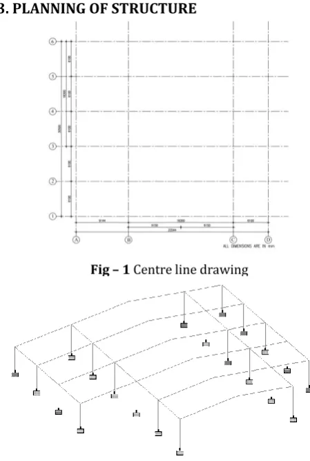
[image:3.595.311.536.100.434.2]3. PLANNING OF STRUCTURE
Fig – 1 Centre line drawing
Fig – 2 Frame STAAD Modeling
4. DIMENSIONAL COMPARISON
4.1 PITCHED ROOF
4.1.1 Columns
Hyderabad Bangalore
Depth of section at
top node, Dt(H) = 450 mm 450 mm
Depth of section at
bottom node, Db(H) = 350 mm 250 mm
Thickness of web, tw = 8 mm 8 mm
Width of flange, bf = 210 mm 160 mm
Thickness of flange, tf = 12 mm 12 mm
4.1.2 Back Columns
© 2019, IRJET | Impact Factor value: 7.211 | ISO 9001:2008 Certified Journal | Page 4787
Depth of section attop node, Dt(H) = 450 mm 450 mm
Depth of section at
bottom node, Db(H) = 350 mm 300 mm
Thickness of web, tw = 8 mm 8 mm
Width of flange, bf = 220 mm 200 mm
Thickness of flange, tf = 13 mm 12 mm
4.1.3 Rafter 01
Hyderabad Bangalore
Depth of section at top
node, Dt(H) = 410 mm 350 mm
Depth of section at
bottom node, Db(H) = 370 mm 330 mm
Thickness of web, tw = 6 mm 6 mm
Width of flange, bf = 150 mm 160 mm
Thickness of flange, tf = 8 mm 8 mm
4.1.4 Rafter 02
Hyderabad Bangalore
Depth of section at
top node, Dt(H) = 370 mm 330 mm
Depth of section at
bottom node, Db(H) = 330 mm 310 mm
Thickness of web, tw = 6 mm 6 mm
Width of flange, bf = 150 mm 150 mm
Thickness of flange, tf = 8 mm 8 mm
4.1.5 Rafter 03
Hyderabad Bangalore
Depth of section at top
node, Dt(H) = 330 mm 310 mm
Depth of section at
bottom node, Db(H) = 290 mm 290 mm
Thickness of web, tw = 6 mm 6 mm
Width of flange, bf = 150 mm 150 mm
Thickness of flange, tf = 8 mm 8 mm
4.1.6 Rafter 04 to 07
Hyderabad Bangalore
Depth of section at
top node, Dt(H) = 290 mm 290 mm
Depth of section at
bottom node, Db(H) = 290 mm 290 mm
Thickness of web, tw = 6 mm 6 mm
Width of flange, bf = 150 mm 150 mm
Thickness of flange, tf = 6 mm 6 mm
4.2 LEFT MONOSLOPE ROOF
4.2.1 Columns
Hyderabad Bangalore
Depth of section at top
node, Dt(H) = 250 mm 225 mm
Depth of section at
bottom node, Db(H) = 200 mm 225 mm
Thickness of web, tw = 6 mm 6 mm
Width of flange, bf = 130 mm 125 mm
Thickness of flange, tf = 8 mm 8 mm
4.2.2 Rafter 01
Hyderabad Bangalore
Depth of section at
top node, Dt(H) = 390 mm 330 mm
Depth of section at
bottom node, Db(H) = 410 mm 350 mm
Thickness of web, tw = 6 mm 6 mm
Width of flange, bf = 150 mm 150 mm
© 2019, IRJET | Impact Factor value: 7.211 | ISO 9001:2008 Certified Journal | Page 4788
4.2.3 Rafter 02
Hyderabad Bangalore
Depth of section at top
node, Dt(H) = 370 mm 310 mm
Depth of section at
bottom node, Db(H) = 390 mm 330 mm
Thickness of web, tw = 6 mm 6 mm
Width of flange, bf = 150 mm 150 mm
Thickness of flange, tf = 8 mm 8 mm
4.2.4 Rafter 03
Hyderabad Bangalore
Depth of section at
top node, Dt(H) = 350 mm 290 mm
Depth of section at
bottom node, Db(H) = 370 mm 310 mm
Thickness of web, tw = 6 mm 6 mm
Width of flange, bf = 150 mm 150 mm
Thickness of flange, tf = 8 mm 8 mm
4.2.5 Rafter 04
Hyderabad Bangalore
Depth of section at top
node, Dt(H) = 330 mm 270 mm
Depth of section at
bottom node, Db(H) = 350 mm 290 mm
Thickness of web, tw = 6 mm 6 mm
Width of flange, bf = 150 mm 150 mm
Thickness of flange, tf = 6 mm 6 mm
4.2.6 Rafter 05
Hyderabad Bangalore
Depth of section at
top node, Dt(H) = 310 mm 250 mm
Depth of section at
bottom node, Db(H) = 330 mm 270 mm
Thickness of web, tw = 6 mm 6 mm
Width of flange, bf = 150 mm 150 mm
Thickness of flange, tf = 6 mm 6 mm
4.2.7 Rafter 06
Hyderabad Bangalore
Depth of section at top
node, Dt(H) = 290 mm 230 mm
Depth of section at
bottom node, Db(H) = 310 mm 250 mm
Thickness of web, tw = 6 mm 6 mm
Width of flange, bf = 150 mm 150 mm
Thickness of flange, tf = 6 mm 6 mm
4.2.8 Rafter 07
Hyderabad Bangalore
Depth of section at
top node, Dt(H) = 270 mm 210 mm
Depth of section at
bottom node, Db(H) = 290 mm 230 mm
Thickness of web, tw = 6 mm 6 mm
Width of flange, bf = 150 mm 150 mm
Thickness of flange, tf = 6 mm 6 mm
4.3 RIGHT MONOSLOPE ROOF
4.3.1 Columns
Hyderabad Bangalore
Depth of section at top
node, Dt(H) = 250 mm 225 mm
Depth of section at
© 2019, IRJET | Impact Factor value: 7.211 | ISO 9001:2008 Certified Journal | Page 4789
Thickness of web, tw = 6 mm 6 mmWidth of flange, bf = 130 mm 125 mm
Thickness of flange, tf = 8 mm 8 mm
4.3.2 Rafter 01
Hyderabad Bangalore
Depth of section at
top node, Dt(H) = 410 mm 350 mm
Depth of section at
bottom node, Db(H) = 390 mm 310 mm
Thickness of web, tw = 6 mm 6 mm
Width of flange, bf = 150 mm 150 mm
Thickness of flange, tf = 8 mm 8 mm
4.3.3 Rafter 02
Hyderabad Bangalore
Depth of section at top
node, Dt(H) = 390 mm 310 mm
Depth of section at
bottom node, Db(H) = 370 mm 270 mm
Thickness of web, tw = 6 mm 6 mm
Width of flange, bf = 150 mm 150 mm
Thickness of flange, tf = 8 mm 8 mm
4.3.4 Rafter 03
Hyderabad Bangalore
Depth of section at
top node, Dt(H) = 370 mm 270 mm
Depth of section at
bottom node, Db(H) = 350 mm 230 mm
Thickness of web, tw = 6 mm 6 mm
Width of flange, bf = 150 mm 150 mm
Thickness of flange, tf = 8 mm 8 mm
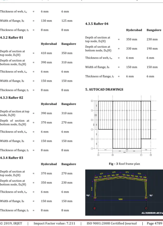
4.3.5 Rafter 04
Hyderabad Bangalore
Depth of section at
top node, Dt(H) = 350 mm 230 mm
Depth of section at
bottom node, Db(H) = 330 mm 190 mm
Thickness of web, tw = 6 mm 6 mm
Width of flange, bf = 150 mm 150 mm
Thickness of flange, tf = 6 mm 6 mm
[image:6.595.36.557.75.795.2]5. AUTOCAD DRAWINGS
© 2019, IRJET | Impact Factor value: 7.211 | ISO 9001:2008 Certified Journal | Page 4790
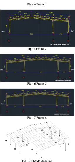
Fig – 4 Frame 1Fig - 5 Frame 2
Fig – 6 Frame 3
Fig – 7 Frame 6
Fig – 8 STAAD Modeling
6. CONCLUSION
Steel is the basic material used for Pre-Engineered Building (PEB). By choosing steel to design a Pre-Engineered Building, it offers low cost, strength, durability, design flexibility, adaptability and recyclability. PEB is the best solution for longer span structures without interior column in between. In this thesis, dimensional comparison of structural elements of a PEB in two different wind zone area (Hyderabad and Bangalore) is done. To conclude, “Pre-Engineered Building construction gives the end users a much
more economical and better solution for long span structures where large column free areas are needed”.
REFERENCES
1. Aijaz Ahmad Zende, Prof.A.V.Kulkarni, Aslam Hutagi (Feb 2013), “Comparative Study of Analysis and Design of Pre-Engineered Buildings and Conventional Frames”, IOSR Journal of Mechanical and Civil Engineering, Volume 5, Issue 1, pp:32-43
2. C.M.Meera (June 2013), “Pre-Engineered Building Design of an Industrial Warehouse”, International Journal of Engineering Sciences & Emerging Technologies, Volume 5, Issue 2, pp:75-82
3. G.Sai Kiran, A.Kailasa Rao, R.Pradeep Kumar (Aug 2014), “Comparision of Design Procedures for Pre-Engineered Buildings (PEB) : A Case Study”, International Journal of Civil, Architectural, Structural & Construction Engineering, Volume 8, No. 4
4. IS 800:2007, “General construction in steel-code of Practice (Third Revision)”, Bureau of Indian Standards, New Delhi, India
5. IS 875:2015, “Design loads (other than Earthquake) for Buildings and Structures, Part 3-Wind Loads”, Bureau of Indian Standards, New Delhi, India
6. Jatin D. Thakar, Prof.P.G.Patel (Sep 2013), “Comparative Study of Pre-Engineered Steel Structure by Varying Width of Structure”, International Journal of Advanced Engineering Technology, Volume 4, Issue 3
7. S.D.Charkal and Latesh S (June 2014), “Economizing Steel Building using Pre-Engineered Steel Sections”, International Journal of Research in Civil Engineering, Architecture & Design, Volume 2, Issue 2
8. SP 64 : 2001, “Explanatory Handbook on Indian Standard Code of Practice for Design loads (other than Earthquake) for Buildings and Structures, Part 3 –Wind Load”, Bureau of Indian Standards, New Delhi, India
9. Syed Firoz, Sarath Chandra Kumar B, S.Kanakambara Rao (Apr 2012), “Design concept of Pre-Engineered Building”, International Journal of Engineering Research & Applications, Volume 2, Issue 2, pp:267-272