ISSN Online: 2327-5901 ISSN Print: 2327-588X
DOI: 10.4236/jpee.2018.611004 Nov. 26, 2018 40 Journal of Power and Energy Engineering
Stabilization of Wind Farm by Using PMSG
Based Wind Generator Taking Grid Codes
into Consideration
Md. Rifat Hazari
1*#, Mohammad Abdul Mannan
2, Atsushi Umemura
1, Rion Takahashi
1,
Junji Tamura
11Department of Electrical and Electronic Engineering, Kitami Institute of Technology (KIT), 165 Koen-cho, Kitami, Hokkaido
090-8507, Japan
2Department of Electrical and Electronic Engineering, American International University-Bangladesh (AIUB), 408/1, Kuratoli,
Khilkhet, Dhaka, Bangladesh
Abstract
This paper presents a new operational strategy for a large-scale wind farm (WF) which is composed of both fixed speed wind turbines with squirrel cage induction generators (FSWT-SCIGs) and variable speed wind turbines with permanent magnet synchronous generators (VSWT-PMSGs). FSWT-SCIGs suffer greatly from meeting the requirements of fault ride through (FRT), be-cause they are largely dependent on reactive power. Integration of flexible ac transmission system (FACTS) devices is a solution to overcome that problem, though it definitely increases the overall cost. Therefore, in this paper, a new method is proposed to stabilize FSWT-SCIGs by using VSWT-PMSGs in a WF. This is achieved by injecting the reactive power to the grid during fault condition by controlling the grid side converter (GSC) of PMSG. The con-ventional proportional-integral (PI)-based cascaded controller is usually used for GSC which can inject small amount of reactive power during fault period. Thus, it cannot stabilize larger rating of SCIG. In this paper, a suitable fuzzy logic controller (FLC) is proposed in the cascaded controller of GSC of PMSG in order to increase reactive power injection and thus improve the FRT capabil-ity of WF during voltage dip situation due to severe network fault. To evaluate the proposed controller performance, simulation analyses are performed on a modified IEEE nine-bus system. Simulation results clearly show that the pro-posed method can be a cost-effective solution which can effectively stabilize the larger rating of SCIG compared to conventional PI based control strategy.
*http://orcid.org/0000-0002-1398-3013
How to cite this paper: Hazari, M.R., Mannan, M.A., Umemura, A., Takahashi, R. and Tamura, J. (2018) Stabilization of Wind Farm by Using PMSG Based Wind Generator Taking Grid Codes into Consid-eration. Journal of Power and Energy Engi-neering, 6, 40-52.
https://doi.org/10.4236/jpee.2018.611004
Received: October 25, 2018 Accepted: November 23, 2018 Published: November 26, 2018 Copyright © 2018 by authors and Scientific Research Publishing Inc. This work is licensed under the Creative Commons Attribution International License (CC BY 4.0).
http://creativecommons.org/licenses/by/4.0/
DOI: 10.4236/jpee.2018.611004 41 Journal of Power and Energy Engineering
Keywords
Wind Turbine Generator, Fuzzy Logic Controller, Power System Stability, Power Converter, PI Controller
1. Introduction
Global warming is one of the serious problems that the world faces recently due to the use of fossil fuel-based power plants to generate electricity [1]. Owing to the drawbacks of conventional power plants, clean energy has grown signifi-cantly since the last decade. Wind power (WP) is one of the clean energy sources which grow significantly since the last decade. According to the global wind energy council (GWEC), the cumulative installation size of WP was 539.1 GW at the end of 2017 and it will reach 840.9 GW by 2022 [2]. This huge installation of WP into the power system has serious impacts on system stability. In order to continue the smooth operation of power grid including WP, FRT necessities have been executed all over the world. It demands that the WF must remain connected to the power grid during a fault event and support the system in a similar way as conventional synchronous generators (SGs) [3].
Most of the WFs are constructed using FSWT-SCIG due to their superior characteristics, e.g., brushless operation, robust construction, operational sim-plicity and low cost [4]. However, the SCIG is directly coupled with the grid sys-tem and does not have FRT capability during network disturbance situation [4]. In addition, the SCIG necessitates large reactive power during fault situations to recover air gap flux. If sufficient reactive power is not injected, the developed electromagnetic torque drops significantly. Usually, a capacitor bank is placed near the SCIG terminal to inject the reactive power. However, the SCIG requires large amount of reactive power during transient period than steady state condi-tion and the capacitor bank is unable to inject this high amount of reactive pow-er during transient ppow-eriod.
In order to improve the FRT capability during network fault situation, some supplementary devices, for example, an energy capacitor system (ECS) [5], super-conducting magnetic energy storage (SMES) [6], and a static synchronous com-pensator (STATCOM) [7] are installed in WFs with FSWT-SCIGs. However, the overall system cost increases.
DOI: 10.4236/jpee.2018.611004 42 Journal of Power and Energy Engineering
reactive power in all grid conditions (normal or disturbed); 5) The converter can fully control the amplitude and frequency of the generator voltage. How-ever, the only drawbacks of VSWT-PMSG are expensive cost due to use of full rating power electronic AC/DC/AC converter. Thus, combined installation of small-scale VSWT-PMSG along with large-scale FSWT-SCIG could be an ef-fective solution. The VSWT-PMSG system can supply additional amount of reactive power during transient period to the FSWT-SCIG. Therefore, the FRT capability of SCIG can be ensured at lower cost. The power converters of PMSG consist of machine side converter (MSC) and GSC. The GSC is respon-sible to inject reactive power to the grid system [11]. Thus, the designing of GSC control strategy is very crucial and equally important. Normally, cascaded con-trol strategy based on four conventional PI concon-trollers is used in the inner and outer loops of GSC controller [11]. But the accomplishment of the conventional PI controller is insufficient during transient period and it cannot provide effec-tive amount of reaceffec-tive power [12]. This is because, for example, conventional PI controller cannot deal with the system non-linearity due to parameter changes in the grid system. According to the deviation of the grid system impedances, gain margin and phase margin of the control system should be changed.
On the other hand, the FLC can handle nonlinear systems very effectively be-cause it offers variable gain during transient conditions. Compared with conven-tional PI controller, FLC has the potential to provide an improved method even in the wide parameter variations. The FLC can take the place of conventional PI controller.
Thus, using an FLC in the inner loop of GSC controller to provide efficient amount of reactive power to stabilize SCIG-based WF during fault periods is convenient. Therefore, the main contribution of this paper is the design of a novel FLC-based GSC controller of PMSG to improve the FRT capability and stabilize the gird-connected SCIG-based WF. Detailed design procedure and control strategies of the overall system are presented in this paper. The effec-tiveness of the proposed control strategy is verified by both transient and dy-namic simulation analyses. Real wind speed data measured in Hokkaido Island, Japan, are used for dynamic study.
The transient performance of the overall system composed of proposed GSC controller controlled PMSG, SCIG, and conventional SGs is compared with that composed of a PMSG controlled by conventional PI-based cascaded controller presented in [11]. Finally, it is found that the proposed FLC-based GSC control-ler is very effective to improve the FRT capability of SCIG-based WF.
DOI: 10.4236/jpee.2018.611004 43 Journal of Power and Energy Engineering
2. Description of Power System Model
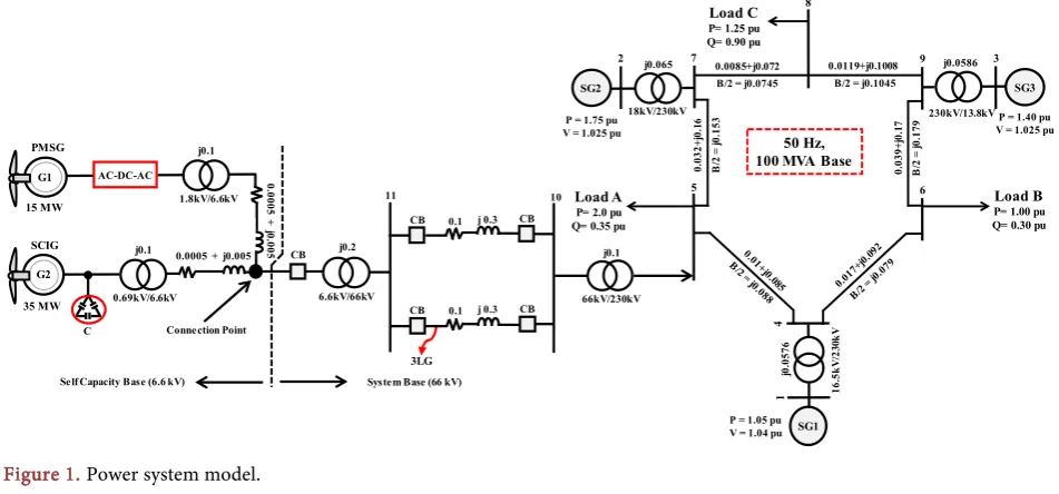
This study employed the power system model illustrated in Figure 1 for tran-sient stability and dynamic performance analyses. It is composed of IEEE nine-bus main model and a WF. The main system consists of three conventional SGs (SG1 rating: 150 MVA, SG2 rating: 250 MVA and SG3 rating: 200 MVA). IEEE type AC4A exciter model presented in [13] is considered for all SGs. The SG1 and SG2 are thermal power plants whereas SG3 is a hydro power plant. The models and parameters of thermal and hydro governor systems are taken from
[13]. The WF is connected to bus 5 through double circuit transmission lines, transformers, and it consists of one SCIG (rated capacity: 35 MW) and one PMSG (rated capacity: 15 MW) as shown in Figure 1. The total capacity of WF is 50 MW. Each PMSG and SCIG are denoted by an aggregated equivalent single generator to decrease computational time [14] [15]. The parameters of conven-tional SGs, SCIG, and PMSG are presented in Appendix.
3. Wind Turbine Model
The extracted mechanical power from a wind turbine can be expressed as [8]:
(
)
2 3
0.5 ,
w w p
P =
ρπ
R V Cλ β
(1)where,
(
)
2 51 3 4 6
, i
c p
i
c
C
λ β
c cβ
c eλ cλ
λ
−
= − − +
(2)
3
1 1 0.035
0.08 1
i
λ =λ− β β− + (3)
r
w
R V
ω
λ= (4)
[image:4.595.64.540.507.729.2]where, Pw = Captured wind power, ρ = Air density (KG/m3), R = Radius of the
Figure 1. Power system model.
18kV/230kV 230kV/13.8kV 16. 5k V/ 23 0k V j0.065 j0.0586 j0. 0576
2 7 9 3
5 6 4 1 SG2 SG1 SG3 Load C
P= 1.25 pu Q= 0.90 pu
Load B
P= 1.00 pu Q= 0.30 pu
Load A
P= 2.0 pu Q= 0.35 pu
8
0.0085+j0.072 B/2 = j0.0745
0.0119+j0.1008 B/2 = j0.1045
0. 032+ j0. 16 B /2 = j0. 153 0. 039+ j0. 17 B /2 = j0. 179 50 Hz, 100 MVA Base
P = 1.75 pu V = 1.025 pu
P = 1.40 pu V = 1.025 pu
P = 1.05 pu V = 1.04 pu G1 1.8kV/6.6kV j0.1 AC-DC-AC G2 0.69kV/6.6kV j0.1 PMSG SCIG 6.6kV/66kV j0.2
Self Capacity Base (6.6 kV) System Base (66 kV)
0.0005 + j0.005
0. 0005 + j0. 005 Connection Point C
0.1 j 0.3
0.1 j 0.3
DOI: 10.4236/jpee.2018.611004 44 Journal of Power and Energy Engineering
rotor blade (m), Vw= Wind speed (m/s), Cp = Power coefficient, β = Pitch
an-gle,and λ = Tip speed ratio. In addition, c1 to c6 are characteristic coefficients of
wind turbine [16], and ωr = rotational speed of wind turbine (rad/s).
The maximum power point tracking (MPPT) technique shown in Equation (5) is adopted in this work [8].
(
)
22
MPPT 0.5 r opt p opt_
P =
ρπ
Rω λ
C (5)The rotating mass of variable speed wind turbine is composed of rotor hub with blades and generator shaft. The two-mass drive train model is considered in this work [11] [17].
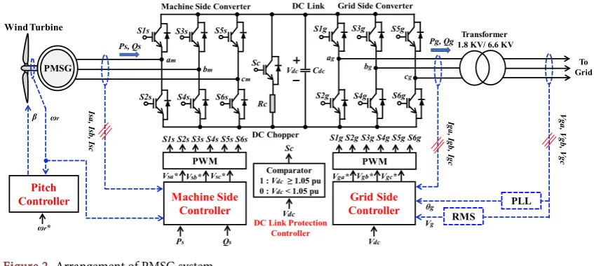
4. PMSG Model and Control System
An arrangement of VSWT-PMSG and control scheme is illustrated in Figure 2. The complete system comprises wind turbine with drive train models, PMSG without gearbox, MSC, GSC, and pitch angle controller. The both converters are built by using two levels of insulated gate bipolar transistor (IGBT), and the machine side controller and the grid side controller are responsible for control-ling them. The MSC is directly associated to the stator terminal of PMSG whe-reas the GSC is attached to the grid system through step up transformers. PMSG model available in PSCAD library is used in this work [18]. A DC chopper is lo-cated in the DC-Link circuit. It is controlled by the comparator block. When the DC-link voltage (Vdc) ≥ 1.05 pu, the comparator activates the DC chopper and
protect the DC-Link circuit. The pulse width modulation (PWM) method is used in this work and the carrier frequency is taken 3.0 kHz for both converters. The rated Vdc is 3.0 kV.
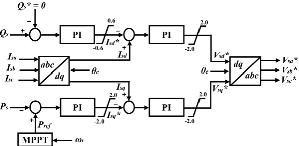
4.1. Machine Side Controller
[image:5.595.116.540.530.720.2]The MSC transforms the three phase AC voltage generated by PMSG to DC vol-tage. The controller for MSC is composed of four conventional PI controllers as depicted in Figure 3. The controller is consisting of two loops; upper loop is for
Figure 2. Arrangement of PMSG system.
PWM Machine Side Controller PWM Ps, Qs Isa , Isb , Isc Grid Side Controller PLL Vga, V gb, V gc Iga, Ig b, Ig c RMS Pg, Qg Vdc Vg θg
Ps Qs
To Grid
S1s S2s S3s S4s S5s S6s S1g S2g S3g S4g S5g S6g S1s S2s S3s S4s S5s S6s S1g S2g S4g S3g S5g S6g Comparator 1 : Vdc≥ 1.05 pu 0 : Vdc< 1.05 pu
Sc
Rc
Cdc Vdc
Sc
Vsa*
PMSG
Wind Turbine Transformer
1.8 KV/ 6.6 KV
Pitch Controller
ωr β
ωr*
Machine Side Converter DC Link Grid Side Converter
DC Chopper
DC Link Protection Controller Vdc am bm cm ag bg cg
DOI: 10.4236/jpee.2018.611004 45 Journal of Power and Energy Engineering
Figure 3. Machine side controller.
reactive power whereas lower one is for active power. The q-axis current (Isq)
and the d-axis (Isd) current control the active power (Ps) and reactive power (Qs)
of the PMSG system, respectively. The reference active power (Pref) is obtained
by the MPPT algorithm described in Section 3. The unity power factor operation is performed by setting the reference reactive power ( *
s
Q ) to zero.
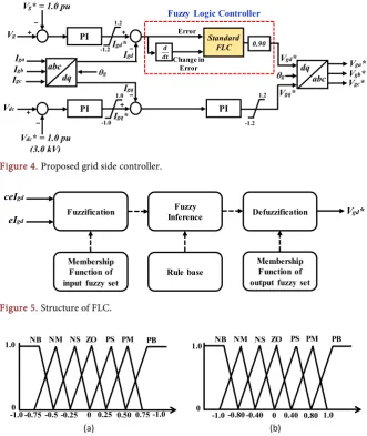
4.2. Grid Side Controller
This chapter describes the proposed controller of GSC and detail design proce-dure of FLC.
4.2.1. Proposed Grid Side Controller Operation
The GSC transforms the DC voltage into three phase AC voltage of the grid fre-quency. Figure 4 depicts the proposed controller for GSC. It is composed of three PI controllers and one FLC. The controller is used to control the reactive power (Qg) delivered to the grid and keep the Vdc constant by using the d-axis
(Igd) and q-axis (Igq) currents of GSC. The FLC is used in the inner loop of the
GSC controller to supply reactive power more efficiently during fault condition. Based on the system parameters, the FLC can provide variable gain. Therefore, it is possible to inject effective amount of reactive power during transient period. Thus, the terminal voltage can quickly be going back to the pre-fault value. In addition, the proposed control strategy can effectively stabilize the SCIG-based WF compared to conventional PI based cascaded GSC controller of PMSG.
4.2.2. Fuzzy Logic Controller Design
In order to design the proposed FLC, the error of the grid d-axis current (eIgd)
and rate of change of the eIgd (ceIgd) are considered as the controller inputs. The
grid d-axis voltage reference ( * gd
V ) is chosen as the controller output. The main structure of the FLC consists of fuzzification, rule base, fuzzy inference, and de-fuzzification as illustrated in Figure 5 [19]. For fuzzification, the triangular membership functions with overlap are used for inputs and output as shown in
Figure 6, in which the linguistic variables NB, NM, NS, ZO, PS, PM, and PB stand for negative big, negative medium, negative small, zero, positive small,
Qs* = 0
PI PI
PI PI
MPPT abc
dq
ωr Qs
Pref Ps
Isa Isd
Isq
Vsd*
Vsq*
Vsa*
θe dqabc
0.6
-0.6
2.0
-2.0
2.0
-2.0
2.0
-2.0
Isq* Isd*
Isb
Isc θ VVscsb**
DOI: 10.4236/jpee.2018.611004 46 Journal of Power and Energy Engineering
Figure 4. Proposed grid side controller.
[image:7.595.209.540.76.207.2]Figure 5. Structure of FLC.
Figure 6. Membership functions: (a) inputs (eIgd, ceIgd), and (b) output (Vgd*).
positive medium, and positive big, respectively. The membership functions have been determined by trial and error approach to obtain the best system perfor-mance.
The rules of fuzzy mapping of the input variables to the output are specified in the form below:
IF <eIgd is PB> and <ceIgd is NS > THEN < Vgd* is PM>
The entire rule base is presented in Table 1, which includes a total of 49 rules. In this work, Mamdani’s max-min method is used as the inference mechanism
[19]. For defuzzification, the center of gravity method is used in order to obtain
* gd
V [19].
5. Simulation Results and Discussion
5.1. Transient Stability Analysis
In this study, simulations were conducted by using PSCAD/EMTDC software on
Vg* = 1.0 pu
PI
PI
abc dq Vg
Iga Igd
Igq θg
1.2
-1.2
1.0
-1.0Igq*
Igd*
Igb Igc
PI
Vgd*
Vgq*
Vga* dq
abc
1.2
-1.2
Vgb* Vgc*
Vdc
Vdc* = 1.0 pu (3.0 kV)
Fuzzy Logic Controller
Standard FLC
𝒅
𝒅𝒕 Change in
Error Error
0.90
θg
Fuzzification InferenceFuzzy Defuzzification
Membership Function of
input fuzzy set Rule base
Membership Function of output fuzzy set
eIgd ceIgd
Vgd*
NB NM NS ZO PS PM PB
-1.0 -0.80 -0.40 0 0.40 0.80 1.0 1.0
0
NB NM NS ZO PS PM PB
-0.75 -0.5 -0.25 0 0.25 0.50 0.75
-1.0 -1.0
1.0
0
DOI: 10.4236/jpee.2018.611004 47 Journal of Power and Energy Engineering
Table 1. Fuzzy rules.
*
gd
V ceIgd
PB PM PS ZO NS NM NB
eIgd
PB PB PB PB PM PM PS ZO PM PB PB PM PM PS ZO NS PS PB PM PM PS ZO NS NM ZO PM PM PS ZO NS NM NM NS PM PS ZO NS NM NM NB NM PS ZO NS NM NM NB NB NB ZO NS NM NM NB NB NB
the power system model illustrated in Figure 1. The FLC was designed using FORTRAN code. For transient stability analysis, three line to ground (3LG) fault near bus 11 was considered as depicted in Figure 1. The fault is considered to happen at 0.1 s, the duration of fault is 0.1 s (5 cycles), the circuit breakers (CBs) on the faulty line are opened at 0.2 s in order to isolate the faulty line from the entire power system and reclosed at 1.0 s. The simulation time is 10.0 s with a solution time step of 5 µs. The wind speed applied to each wind turbine is kept constant at 11.0 m/s based on the assumption that the wind speed does not change dramatically within this short period. Simulations were performed for two cases in order to validate the effectiveness of the proposed FLC controlled GSC controller of PMSG.
Case 1: with conventional cascaded GSC controller of PMSG presented in [11]. Case 2: with proposed cascaded FLC-based GSC controller of PMSG pre-sented in Section 4.2.
The grid code of FRT requirement for WF which is considered in this study is illustrated in Figure 7 [3]. Based on the curve, the wind turbine must stay con-nected with the power system if the voltage dip is within the defined range.
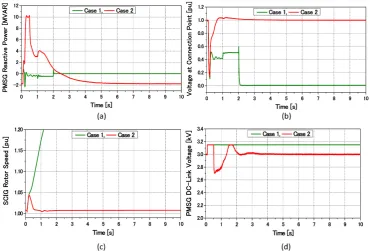
The simulation results of PMSG, SCIG, and SGs are depicted in Figure 8 and
Figure 9, respectively. The reactive power injected by PMSG to the SCIG system in Case 2 is greater than that in Case 1 after a severe network fault as shown in
DOI: 10.4236/jpee.2018.611004 48 Journal of Power and Energy Engineering
[image:9.595.167.538.288.539.2]Figure 7. FRT requirement for WF.
Figure 8. Responses of wind generators: (a) PMSG reactive power, (b) voltage at connection point of
wind generators, (c) SCIG rotor speed, and (d) PMSG DC-Link voltage.
Figure 9. Responses of conventional SGs: (a) SGs rotor speed, and (b) SGs load angle.
time when a fault occurs limit line 1
highest value of the three line-to-line grid voltage U/UN
time in ms 0 150 700 1500 3000
15% 45% 70% 100%
limit line 2
selective disconnection of generators depending on their condition range in which a disconnection is only
permissible by the automatic system lowest value of the
voltage band
(a) (b)
0 1 2 3 4 5 6 7 8 9 10
0.994 0.996 0.998 1.000 1.002 1.004 1.006
S
G
s
Rot
or S
p
e
e
d
[
p
u
]
Time [s]
SG1: Case 1, Case 2 SG2: Case 1, Case 2 SG3: Case 1, Case 2
0 1 2 3 4 5 6 7 8 9 10 0.00
0.04 0.08 0.12 0.16 0.20 0.24 0.28
S
G
s
L
o
a
d A
n
g
le
[
ra
d]
Time [s]
[image:9.595.172.537.589.706.2]DOI: 10.4236/jpee.2018.611004 49 Journal of Power and Energy Engineering Figure 9(a) and Figure 9(b) illustrate the rotor speed and power angle res-ponses of conventional SGs (δSGs) with respect to SG1 load angle (δSG1). It is
clearly seen from the figures that the rotor speed and power angle responses of SGs are more stable in Case 2 than Case 1. As a result, it can be concluded that the VSWT-PMSG with proposed FLC controlled GSC can enhance the transient stability of SGs as well as the voltage stability of the WF during transient condi-tion.
5.2. Dynamic Performance Study
[image:10.595.122.538.402.695.2]In this chapter, analysis about dynamic performance about the proposed GSC controller of PMSG is presented. The same power system model depicted in
Figure 1 is used in this study. The total simulation time is 250.0 s. The real wind speed data measured at Hokkaido Island, Japan, shown in Figure 10(a), is used in the simulation. Figure 10(b) shows the reactive power output of each wind generator. The PMSG supplies the necessary reactive power to the SCIG for vol-tage regulation. Thus, the connection point volvol-tage is approximately constant, as shown in Figure 10(c). Due to the fluctuations in the wind speed of wind gene-rators, the frequency response of the power system is varying as shown in Figure 10(d). But, the frequency fluctuations lie within the permissible limit in Japan (±0.2 Hz).
The dynamic simulation study confirmed that the proposed FLC-controlled
Figure 10. Responses of power system: (a) applied wind speeds to wind generators, (b) reactive power output of
DOI: 10.4236/jpee.2018.611004 50 Journal of Power and Energy Engineering
PMSG system can effectively supply reactive power and thus maintain the con-nection point voltage constant under a randomly varying wind speed.
6. Conclusions
This study proposes the application of fuzzy logic in GSC controller of PMSG to enhance the FRT capability of SCIG-based WF during transient period. The ef-fectiveness of the proposed controller is tested by considering severe 3LG fault. The transient performance of the overall system composed of the proposed FLC-controlled PMSG, SCIG, and conventional SGs is compared with that of PMSG with the conventional control strategy. It is found that the proposed con-trol strategy can ensure the FRT capability of WF as well as power system tran-sient and steady-state stability. Therefore, it can be concluded that the proposed GSC controller for PMSG can be an effective solution to augment the transient stability of the grid-connected WF.
Application of adaptive neuro-fuzzy inference system (ANFIS) based control strategy of GSC for PMSG is strong candidate for future study.
Acknowledgements
This study was supported by the Grant-in-Aid for Scientific Research (B) from The Ministry of Education, Science, Sports and Culture of Japan.
Conflicts of Interest
The authors declare no conflicts of interest regarding the publication of this paper.
References
[1] Ula, A. (1991) Global Warming and Electric Power Generation: What Is the Con-nection? IEEE Transactions on Energy Conversion, 6, 599-604.
https://doi.org/10.1109/60.103631
[2] Global Wind Energy Council (GWEC) (2017) Annual Market Update 2017, Global Wind Report. http://www.gwec.net/
[3] E. ON NETZ GmbH (2006) Grid Connection Regulation for High and Extra High Voltage. E. ON NETZ GmbH, Essen, Germany.
[4] Muyeen, S.M., Mannan, M.A., Ali, M.H., Takahashi, R. and Tamura, J. (2006) Stabi-lization of Wind Turbine Generator System by STATCOM. IEEJ Transactions on Power and Energy, 126-B, 1073-1082.
[5] Muyeen, S.M., Takahashi, R., Ali, M.H., Murata, T. and Tamura, J. (2008) Transient Stability Augmentation of Power Systems Including Wind Farms Using ECS. IEEE Transactions on Power Systems, 23, 1179-1187.
https://doi.org/10.1109/TPWRS.2008.920082
[6] Elshiekh, M.E., Mansour, D.A., Zhang, M., Yuan, W., Wang, H. and Xie, M. (2018) New Technique for Using SMES to Limit Fault Currents in Wind Farm Power Sys-tems. IEEE Transactions on Applied Superconductivity, 28, 1-5.
DOI: 10.4236/jpee.2018.611004 51 Journal of Power and Energy Engineering
[8] Muyeen, S.M., Tamura, J. and Murata, T. (2009) Stability Augmentation of a Grid Connected Wind Farm. Springer-Verlag, London.
[9] Arani, M.F.M. and Mohamed, Y.A.I. (2016) Assessment and Enhancement of a Full-Scale PMSG-Based Wind Power Generator Performance under Faults. IEEE Transactions on Energy Conversion, 31, 728-739.
https://doi.org/10.1109/TEC.2016.2526618
[10] Zhao, Y., Qiao, W. and Qu, L. (2015) A Discrete-Time Direct Torque Control for Direct-Drive PMSG-Based Wind Energy Conversion Systems. IEEE Transactions on Industry Applications, 51, 3504-3514. https://doi.org/10.1109/TIA.2015.2413760 [11] Rosyadi, M., Umemura, A., Takahashi, R., Tamura, J., Uchiyama, N. and Ide, K.
(2015) Simplified Model of Variable Speed Wind Turbine Generator for Dynamic Simulation Analysis. IEEJ Transactions on Power and Energy, 135, 538-549. [12] Ferdi, B., Benachaiba, C., Dib, S. and Dehini, R. (2010) Adaptive PI Control of
Dy-namic Voltage Restorer Using Fuzzy Logic. Journal of Electrical Engineering: Theory and Application, 1, 165-173.
[13] Kundur, P. (1994) Power System Stability & Control. McGraw-Hill Inc., 2 Pennsyl-vania Plaza New York City.
[14] Ackerman, T. (2005) Wind Power in Power System. John Wiley & Sons, UK. https://doi.org/10.1002/0470012684
[15] WECC Renewable Energy Modeling Task Force (2014) WECC Wind Power Plant Dynamic Modeling Guide.
[16] Matlab Documentation Center (2018) http://www.mathworks.co.jp/jp/help/ [17] Miller, N.W., Pric, W.W. and Samches-Gasca, J.J. (2003) Dynamic Modeling of GE
DOI: 10.4236/jpee.2018.611004 52 Journal of Power and Energy Engineering
Appendix
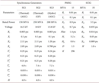
[image:13.595.209.538.152.426.2]The SGs, PMSG, SCIG, and drive train parameters used in this study are given in
Table A1.
Table A1. Parameters of conventional SGs and wind generators.
Synchronous Generators PMSG SCIG
Parameters
SG1 SG2 SG3 MVA 15 MVA 35 (Thermal)
(AGC) (Thermal) (GF) (Hydro) (AGC)
Rs 0.01 pu R1 0.01 pu
Ls 0.1 pu X1 0.1 pu
Rated Power 150 MVA 250 MVA 200 MVA Xd 0.9 pu Xm 3.5 pu
Voltage 16.5 kV 18 kV 13.8 kV Xq 0.7 pu R21 0.035 pu
Ra 0.003 pu 0.003 pu 0.003 pu Flux 1.4 pu R22 0.014 pu
Xl 0.1 pu 0.1 pu 0.1 pu Ht 5.2 s X21 0.03 pu
Xd 2.11 pu 2.11 pu 1.20 pu Hg 0.8 s X22 0.089 pu
Xq 2.05 pu 2.05 pu 0.700 pu D 1.5 H 1.0 s
d
X′ 0.25 pu 0.25 pu 0.24 pu K 296
d
X′′ 0.21 pu 0.21 pu 0.20 pu
q
X′′ 0.21 pu 0.21 pu 0.20 pu
do
T′ 6.8 s 7.4 s 7.2 s
do
T′′ 0.033 s 0.033 s 0.031 s
qo
T′′ 0.030 s 0.030 s 0.030 s