ISSN Online: 2327-5227 ISSN Print: 2327-5219
DOI: 10.4236/jcc.2018.69008 Sep. 21, 2018 106 Journal of Computer and Communications
The Performance Analysis of Multi-Layer
Split-Protocol
Bharat S. Rawal
Department of Information Science and Technology Pennsylvania State University, Abington, PA, USA
Abstract
The growing need for high-performance networking is achieved with parallel processing; several networking functions are processed concurrently in order to accomplish a performance Networking Architecture. Open systems inter-connection (OSI) model is an example of multi-layering structure, and each layer performs definite function unique to that layer. OSI model works on pass it on principle, and it is divided in two stacks lower stack and upper stack. Layers 4 - 7 represent upper stack and responsible for data applications. The remaining 1 - 3 layers represent the lower stack and mostly involve in data movement. There are many techniques are available for server optimiza-tion enhancing the availability by distributing the load among peer servers. According to our knowledge, nobody has implemented such splitting archi-tecture across the entire OSI model. In this paper, we present multilayer Split-protocol (MLSP) a high performance, reliable and secure technique for spiting an application or network protocol across OSI model, and we present the design, implementation, and empirical performance evaluation of MLSP. It is the ideal choice for Cloud services where each functional component is considered an independent of each other.
Keywords
OSI Model, Bare Machine Computing, Split-Protocol, M-TCP, Web Server, Reliability, Availability, Performance
1. Introduction
Web server security and load delivery between Web servers are significant chal-lenges that remain to be resolved using a range of methods. In specific, load-balancing and splitting techniques are employed at numerous layers of the protocols tack to segment the load among a cluster of Web servers [1] [2]. A P2P How to cite this paper: Rawal, B.S. (2018)
The Performance Analysis of Multi-Layer Split-Protocol. Journal of Computer and Communications, 6, 106-125.
https://doi.org/10.4236/jcc.2018.69008
Received: July 19, 2018 Accepted: September 18, 2018 Published: September 21, 2018
Copyright © 2018 by author and Scientific Research Publishing Inc. This work is licensed under the Creative Commons Attribution International License (CC BY 4.0).
http://creativecommons.org/licenses/by/4.0/
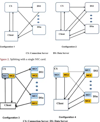
DOI: 10.4236/jcc.2018.69008 107 Journal of Computer and Communications application such as Bitterant (or anything else named “torrent”), Gnutella, Lime Wire, and KaZaA are some examples of P2P applications. P2P applications work by letting your computer down load parts of files from multiple sources on the Internet at the same time [3]. We propose a technique for splitting web request at various layers. At upper layers (5 - 7) an application data and bottom layers (1 - 4) mostly moving data around. HTTP/TCP connection between Web servers permits one server to manage a connection establishment and others to accom-plish data transfer. We are splitting TCP connections in such way that it allows servers to distribute the load without the central authority or any client’s help. Each server has multiple NIC cards. These NIC cards can function unidirection-al or bi-directionunidirection-ally based on a server’s unidirection-algorithm. Details of different type’s HTTP splitting into two servers are explained in [4] [5]. Figures 1-3 describes splitting in to multiple servers with a different configuration. Split-protocol is used for improving security, availability, and reliability of server system [6] [7]. Jaliya and Fox have described several different studies of clouds and cloud technolo-gies on both real applications and standard benchmark. They found that cloud technologies work well for most pleasingly-parallel problems (“Map-only” and “Map-reduce” classes of applications) [8].
[image:2.595.211.538.501.693.2]Novelty and our original contribution: According to our knowledge we have not found any existing technique which splits a single web service on multiple servers, and each server performs the function of an individual or multiple OSI layers. The OSI reference model illustrates the layered architecture, at every layer specific actions, functions, and services take place. We can divide network func-tionality into seven subprocesses and implement similar to the OSI model. The multi-layer splitting offers an efficient load balancing; minimizing the depen-dency; improves the reliability by distributing the functionality over numerous servers; reduces the system complexity and improves performance and the sys-tem security.
Figure 1. Split architecture.
Inter- Server Packet
Network SYN
ACK GET DATA-ACK FIN-ACK
DATA
SYN-ACK GET-ACK FIN-ACK-ACK
CS DS
Client
DOI: 10.4236/jcc.2018.69008 108 Journal of Computer and Communications Figure 2. Splitting with a single NIC card.
Figure 3. Splitting between two NIC cards.
The remainder of the paper is organized as follows. Section II exhibits related work and Section III talks about some performance enhancing techniques. IV describes multilayer splitting architecture. Section V presents M/M/1 and M/M/S Queuing systems. Section VI outlines the MLSP implementation, and Section VII defines performance metrics. Section VIII presents performance. Section IX details the signification of MLSP. And section X highlights an ac-knowledgment. Section XI holds the conclusion.
2. Related Work
DOI: 10.4236/jcc.2018.69008 109 Journal of Computer and Communications has not been introduced earlier. Splitting is comparable to the M-TCP protocol to transfer TCP connections from one server to another [10]. TCP connection splitting and the in [11], staticanalys is techniques are used to analyze the code of Linux device drivers. Also, the communication between controllers, the OS, and the hard ware is monitored. In [12], hard ware abstraction and APIs for de-vices and software interfaces are employed as a foundation for producing device drivers [13]. The Uniform Driver Interface (UDI) is designed for generating de-vice drivers that are manageable concerning platforms and OSs [14]. The Net-work Driver Interface Specification (NDIS) separates the NIC from its driver and defines a standard interface between upper and lower layer controllers [15]. The NDIS library is supported by many Windows versions, while the NDIS wrapper [16] enables Windows drivers to be used with Linux. [17] uses TCP slicing for performance guarantee for cluster-based internet services. In [18], an approach for driver reuse is proposed, where a virtual machine is used to run a driver with its original OS. Various methods applied for load balancing share some essential features. For example, both load balancing and TCP connection splitting enable a server load to be allocated between servers. In layer-2 (link layer) load balancing, various links function as a unique virtual connection, and in layer-4 (transport layer) load balancing, applications are processed based on port numbers and IP addresses. In layer-7 load balancing [17], content know-ledge from the HTTP request is accepted to perform load-balancing judgments. In this case, there are two TCP connections that are spliced [18]. G. Anastasi [19] examined the BitTorrent scheme and completed the preliminary study. Gummadi et al. [20] investigated the prevalence of P2P content across the In-ternet and described the “download at most once” feature of P2P clients. Saroiu [21] [22] characterized the P2P traffic over the Internet, including Napster, Gnutella, and KaZaa systems. Izal [21] investigated a five-month workload of an individual BitTorrent method for software delivery that required thousands of peers. Bellissimo and Izal each estimated the realization of BitTorrent at the flash crowd period [22] [23]. The security aspect of the splitting technique is demon-strated in earlier publications [7] [24] [25]. Most of the existing related work splitting needs some shorts of client involvements and requires some central controlling mechanism for communicating between peers. Existing techniques heavy weight communication overhead affects the performance of overall sys-tems. In our technique there is only two packets of 168 byte are involved for in-ter server communication and it does not require any client’s involvement. Spit-ing process is entirely transparent to client.
3. Performance Enhancing Techniques
3.1. Pipeline
DOI: 10.4236/jcc.2018.69008 110 Journal of Computer and Communications create a pipe. Typically, pipeline does not reduce the proper time execution; in-stead, it improves performance, throughput. A computer processor pipeline is from time to time shared with an instruction pipeline and an arithmetic pipe-line. The instruction pipeline signifies the phases in which a step is progressed through the processor, including it is being drawn, possibly buffered, and then executed. Moreover, the arithmetic pipeline embodied the portions of a mathe-matic operation that can be broken down and overlapped as they are performed [18]. A similar technique used in dynamic random-access memory (DRAM), in which the memory loads the required memory subjects into a small cache com-posed of static random-access memory (SRAM) and then immediately begins fetching the next memory contents. This makes a two-stage pipeline, wherein read instruction is one stage written to memory is in the other phase [14]. The Uniform Driver Interface (UDI) is designed for generating device drivers that are manageable concerning platforms and OSs [6].
3.2. Parallel Computing & Distributed Computing
Distributed computing and parallel computing are frequently deliberated simi-lar, though there is a trivial difference between them. Parallel computing denotes a tightly coupled system with each other. If we look closely at parallel compu-ting, it relates to the technique in which computation is divided between various processors who are sharing the collective memory. The uniformity describes the design of parallel computing. The cluster of nodes connected through an InfiniB and network which is configured with shared memory. Distributed computing, on the other hand, comprises any design or scheme in that computation is frag-mented into parts and are performed simultaneously on unalike computing components, they may be multiprocessors on the same node, another computer or cores within the same CPU [26] [27].
4. Multilayer Split Architecture
DOI: 10.4236/jcc.2018.69008 111 Journal of Computer and Communications without using the DS. In general, there can be a set of n (≥2) servers that can delegate requests to each other.
A given request is split at the GET command as shown in Figure 1. The CS handles the connections, and the DS handles the data transfer. In addition to connections, the CS also handles the data ACKs and the connection closing. The CS has complete knowledge of the requested file, its name, size, and other attributes, but it may or may not have the file itself. However, the DS has the file and serves the data to the client. When a TCP connection is split in this manner, the TCP sliding window information is updated by S1 based on received ACKs even though the data file is sent by S2. Likewise, S2 knows what data has been sent, but it lacks knowledge of what data has been actually received by the client. Thus, retransmissions require that ACK information be forwarded by S1 to S2 using delegate messages as described below. The number of delegate messages exchanged should be kept to a minimum since they add overhead to the system and degrade performance.
When a client makes a request to S1, its connection is based on (IP3, Source-Port) (IP1, 80). S1 can serve this request to a client directly, or it can utilize its DS, which is S2, to serve data. The decision to use a DS can be made based on several factors such as the maximum number of requests that can be processed at S1, the maximum CPU utilization at S1, or resource file location. Alternative-ly, a load balancing algorithm could be used. When S1 chooses to use S2 as a DS, it proceeds as follows. After the GET command is received, it sends an ACK to the client and also sends a delegate message DM1 to S2 (e.g. DM1). The message DM1 contains the state of the request that is stored in S1 in the form of an entry in the TCP table (referred to as a TCB entry). When DM1 reaches the DS, it creates its own TCB entry and starts processing this request as if it was initiated in the DS itself. When a DS sends data to the client it uses the CS’s IP (IP1).
DOI: 10.4236/jcc.2018.69008 112 Journal of Computer and Communications are both on the same LAN, S1 can simply encapsulate the message in a MAC layer frame addressed to MAC S2 (i.e., it does not need an IP address to receive delegate messages from S1). Thus, with these assumptions, switches and routers do not need any special configuration for split connections to work.
However, if S1 and S2 are on LANs with different subnet prefixes (or in gen-eral, on WANs or different networks) and communicate through routers, S2 is not reachable using IP address IP1 since its prefix is not consistent with the network it is on. So, it will need to use its own IP address IP2 to receive packets including delegate messages from S1. This means that the router for S2 must have an ARP entry (IP2, MAC S2) for forwarding to S2, which will only be present if S2 has responded to ARP request for IP address IP2 with its MAC S2. But in this case, if S2 is also sending data to a client using IP address IP1 as source, it raises a security issue due to IP address spoofing. Such IP address spoofing may cause problems with firewalls due to sending topologically incor-rect packets. For splitting to work in this case, note that S1 must send and re-ceive with IP address IP1, whereas S2 must send with IP address S1 and rere-ceive with IP address S2. Now S1 and S2 cannot both delegate to each other, since it is not possible for both machines to send and receive using both IP addresses IP1 and IP2. There are also TCP issues with splitting due to its sliding window, dup-licate acks, fast retransmit, and congestion control that need further study. More delegate messages could be used to address some of these TCP issues, but this would have a negative performance impact.
As the connection and data transfer are split in the architecture, there is a need to send one or more DM messages (DM2s) to DS. At least one DM2 mes-sage is needed to indicate that CS received the FIN-ACK. If a received ACK in-dicates that data is lost, retransmission is needed. One or more DM2s are needed to handle retransmissions since the DS does not receive any data ACKs. The CS monitors the data ACKs and decides to send DM2s as needed. Throughout the splitting process, the client is not aware of DS, and there is no need to involve the client (unlike M-TCP). The last DM2 message to DS is used to terminate when all data has been acknowledged by the client.
Splitting results in two possible overheads. Network traffic due to sending DMs to DS, and the latency encountered at the client due to DM transmission on the LAN (or WAN) from CS to DS. In a LAN environment, this latency is negligible, but may be larger in a WAN or Internet environment. The network traffic generated for each request is at least two DM packets; in most cases it is two packets assuming no retransmissions. If the DM packet is small (168 bytes in a bare PC), the network overhead will be reduced. However, one needs to consider the above two overheads of the split request architecture for a given ap-plication.
DOI: 10.4236/jcc.2018.69008 113 Journal of Computer and Communications clients do not require any prior knowledge of DSs. The CS can also process a given request without using the DS. In general, there can be a set of n (≥2) serv-ers those can delegate requests to each other.
When a client requests CS, its connection is based on (IP, Source Port) (IP1, 80). S1 can serve this request to a client directly, or it can utilize its DS, which is DS1, to serve data. The decision to use a DS can be made based on several fac-tors such as the maximum number of requests that can be administered at CS, the maximum CPU utilization at CS, or resource file location. Alternatively, a load-balancing algorithm could be used. When CS chooses to use DS, it proceeds as follows. After the GET command is received, it sends an ACK to the client and sends a delegate message (DM1) to DS. The message DM1 encompasses the state of the request that is kept in CS as TCB records. When DM1 reaches the DS, it creates its TCB entry and starts processing this application as if it was initiated in DS itself. When a DS directs data to the client, it uses the CS’s IP (IP1).
Figure 2 represents two split configurations 1 & 2 with only one NIC card. In configuration 1, DSs just sends data packets to the clients and does not send any other kinds of packets to the clients.
[image:8.595.211.535.491.704.2]In configuration 2, the DSs dose sends other types of packets to clients. Figure 3 represents two split configurations 3 & 4 with two NIC cards. In configuration 3, DSs only sends data packets to the clients and does not send any other types of packets to the clients. CS and DSs both receive all packets through NC1 and transmit through NC2. In configuration 4, DSs do receive/send other types of packets to the clients. Also, CS and DSs both receive all packets through NC1 and transmit through NC2 respectively [28].
Figure 4 represents partial delegation CS and DS both can send data packets and NIC1 & NIC2 both can receive and transmit data (full duplex).
DOI: 10.4236/jcc.2018.69008 114 Journal of Computer and Communications
5. M/M/1 and M/M/S Queuing System
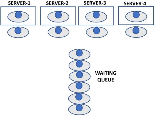
As shown in Figure 5, MLSP system with a single queue with more than one parallel server, then we have M/M/S queuing system, in the diagram below four identical servers severing a request coming into a single queue [19].
The arrival rate λ, Service rate is µ, the ratio of traffic intensity
Ρ = λ/µ (1) Lq = Ls − LB (2) Lq is average number costumer in the waiting line for services, Wq is average time customer spend in the waiting line for services
Ws = Wq + (1/µ) (3) We are reproducing hear the analytical model of split-system as shown in Figures 5-8, represents a Non-split system. It has to perform both tasks of CS and DS (establishing a connection and serving data) [29]; which is similar to single-channel, multiphase system. For one http request, the system is locked for entire time t and can offer µ = mean service rate. A split system become sidle af-ter t/2 time and offers 2 µ mean service rate.
Figure 7 shows the non-resource sharing systems non-split system and Figure 7. Illustrate the resource sharing non-split system and Multichannel, sin-gle-phase system.
Figure 8 demonstrates split system two hardware systems and each hardwares has two software components CS and DS. This system is similar to Multichan-nel, multiphase system.
We will consider the case that the server can serve limited http requests. The waiting queue is regarded as a finite queue.
[image:9.595.233.509.500.706.2]Where λ = mean arrival rate, µ = mean service rate, and n = the number of request in the waiting line system and the probability is described in (1).
Figure 5. M/M/s queuing system.
V
Vs1 V V
SERVER-1 SERVER-2 SERVER-3 SERVER-4
DOI: 10.4236/jcc.2018.69008 115 Journal of Computer and Communications Figure 6. Non-split and split systems.
Figure 7. Non-recourse sharing non-split system.
Figure 8. Resource sharing non-split system.
Non-Split system; Single-channel, multiphase system 5a.
5b.
[image:10.595.242.510.508.702.2]DOI: 10.4236/jcc.2018.69008 116 Journal of Computer and Communications
(
) (
)
( 1)0 1 1
M
µ µ
λ
λ
+Π = − −
[ ]
0n
n
λ
µΠ = Π where n ≤ M
[ ]
(
) (
)
( 1)(
)
( 1)( 1)
1 M M 1 M
E N λ µ λ µ λ µ + λ µ +
− +
= − − (4)
Πn is the probability of n http request being in the server system. Let M is the
maximum requests in the system, and ΠM is a value Πn when n = M.
We can define the probability that a http request (job) not join the system [28] in (2).
[ ]
[ ]
(
1)
E Nq =E N −λ −π M µ
[ ]
[ ]
(
1)
E R =E N λ −πM
[ ]
[ ]
1E Rq =E R − µ (5) We will compare the average response E [Rs] shown in (3), (4) and (5) and E [Rc] time described (6) and (7) by for the separate and non-split queuing sys-tems respectively as illustrated in Figure 7 and Figure 8. The first system cor-responds to two independents M/M/1 queues, with ρ = λ/2µ [29].
[ ]
( ) (
1 1 2)
2 2(
)
E Rs = µ −λ µ = µ λ− (6)
On the other hand, the shared queue sharing system in Figure 10 is represented by M/M/2 system. To obtain E [Rc] first, we will calculate E [Nc].
[ ]
( )
2(
)
20
2 2 2! 1
E Nc =
ρ ρ ρ
+ −π
−ρ
(7)where π0 = −
(
1 ρ) (
1+ρ)
(8)[ ]
2(
1 2)
E Nc =
ρ
−ρ
[ ]
[ ]
1(
(
1 2)
)
4(
4 2 2)
E Rc =E Nc = µ −ρ = µ µ −λ (9)
We have
[ ]
2 2(
)
4 2(
4 2 2)
[ ]
E Rs =
µ λ
− =µ
+λ
µ
−λ
>E Rc (10)This indicates the common queue system is better than a separate-queue sys-tem [29]. Figure 9 represents a Split-system with a balanced (optimized) source sharing common queue system. Therefore, it naturally offers a better re-sponse time than the non-split system.
6. Multilayer Splitting Protocol Implementation
For simplicity, we have implemented the division of functionality according to the TC/IP layering structure. For this experiment, we have spliced server func-tionality between Connection Server (CS) and data servers (DSs).
1) At the Application Layer: HTTP protocol and encryption/decryption splitting have been performed.
2) Host-to-Host Transport Layer: TCP/UDP code is split between CS and DS.
DOI: 10.4236/jcc.2018.69008 117 Journal of Computer and Communications Figure 9. Resource sharing split-system.
Figure 10. Lan Network topology.
Address Resolution Protocol (ARP) performed between CS/DS.
4) At the Network Interface, Layer: Ethernet and implementation of soft-ware as a driver for a network interface card (NIC) shared between CS and DS.
DOI: 10.4236/jcc.2018.69008 118 Journal of Computer and Communications parameters are also different from the driver. In essence in the NIC and the driver, send and receive paths can be treated as two separate entities. In the BMC Web server implementation send and receive, paths are also different. When a packet is received in RDL, its Ethernet header is removed and sent to IP. Then an IP header is removed and sent to TCP. For a given client’s IP address and Port#, a different request is formed at the TCP and a unique entry is created at a TCP block table (TCB). This unique entry is kept in the TCB until the comple-tion of a client’s request. The Ethernet card will send packets from TDL and re-ceive packets into RDL. As it is observed, send and rere-ceive paths are isolated in BMC Web server design.
7. Performance Metrics
1) Peak rate: the maximal processing rate that can be theoretically achieved when all processors (CPUs) are fully consumed [29].
2) Speedup: measures the gain we can achieve by using certain parallel processing to run a given parallel application in order to solve an explicit prob-lem [29].
S = Ts/Tp = 838.829/220.78625 = 3.799280979 (11) TS: execution time needed with the sequential algorithm; Tp: execution time required with the parallel algorithm.
3) Efficiency: this metric narrates the speedup to the number of processors used; by this, it provides a quantity of the ability with which the processors are used [29].
E = S/P = 3.7999280979/4 = 0.949820245 (12) S: speedup; P: number of processors.
For the ideal situation, in theory: S = P; which means E = 1.
We can notice that if we increase the number of processors (DSs) in the MLSP system, practically we can approach closer to the ideal efficiency of 1.
8. The Performance Analysis of MLSP and Non-MLSP
Systems
8.1. Experimental Setup
DOI: 10.4236/jcc.2018.69008 119 Journal of Computer and Communications
8.2. Measurements and Analysis
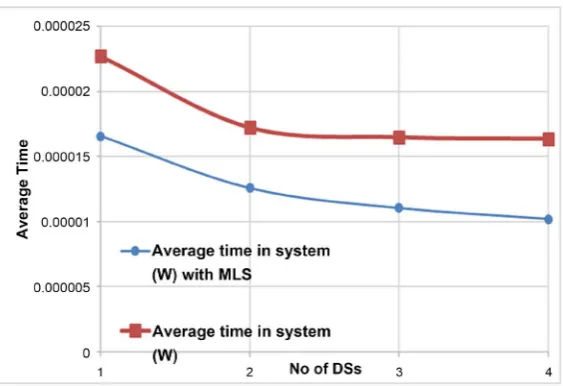
[image:14.595.218.535.469.700.2]In Figures 10-14, a red line represents M/M/s queuing system with four parallel arrangements, and the blue line serve M/M/s queuing system with MLSP. The resource file size is 16 KB bytes and the rate of arrival 2000 requests/sec. From Figure 11, we can see that the CPU utilization reduces exponentially with an in-crease in a number of servers.
From Figure 12, we can notice that with a system of two server numbers in the waiting line is higher in the MLSP system due to inter-server communication overhead. It drastically reduces the increase in the number of servers almost all requests are allocated to the server without any significant delay.
In Figure 13, the average number of requests in the system is always less with the MLSP system. From Figure 14, we can notice that each request spent fewer average time in the MLSP system than regular M/M/s queuing system.
In Figure 15, we can notice that the probability of no requests in the system increases with an increase in a number of servers. The probabilities of all servers are busy in the system is roughly around 0.3. And the likelihood of at least one server is ideal in the system reduces with an increase in a number of servers in a system which is what expected with M/M/s queuing system.
1) Internal Timing Comparison: The HTTP protocol timing results, includ-ing the TCP interactions for non-split and split servers. A client request is issued to CS, and it can delegate the request to the DS. The client request involves a re-source file size of 4K to 1GB. A Wireshark packet tracer was used to capture and measure protocol transaction timings. The Wireshark results were used to define the latency overhead incurred in the splitting. The usual latency measured be-tween GET-ACK and Header data is about 20 microseconds without splitting
DOI: 10.4236/jcc.2018.69008 120 Journal of Computer and Communications Figure 12. An average number of requests waiting in line.
Figure 13. Average number of requests in the system.
[image:15.595.234.516.514.707.2]DOI: 10.4236/jcc.2018.69008 121 Journal of Computer and Communications Figure 15. System Probabilities with MLSP system.
and 25 microseconds with splitting into two cards. Due to the inter-server mes-sage, the latency is about 55 microseconds.
2) Connection Times: Figure 16 shows the connection time for various MLSP configuration and varying file sizes. We can notice that Split/Two NIC configuration offers the shortest connection time and No-split/One NIC has the most significant connection timing. Split/Two NIC connection time is on aver-age 88% lower than No-split/One NIC configuration.
3) Response Times: Figure 17 shows the response time for different HTTP request rates. For the small size of 4 K resource file size, the non-split server can process maximum up to 8500 requests/sec.
We can notice that the behavior of connection and response times are similar. We can see that Split/Two NIC configuration offers the lowest connection time and No-split/One NIC has the highest connection timing. Split/Two NIC con-nection time is on an average 59% lower than No-split/One NIC configuration. However, response times start increasing rapidly at the 100 K file size. The rapid surge in response time and connection times due to the accumulation of a large number of HTTP requests under substantial load conditions, and also due to the higher CPU utilization as discussed below.
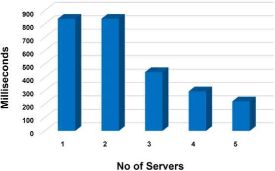
4) Protocol Transaction Time: Figure 18 shows that protocol transaction time for 5965717-byte resource file with two NIC card system.
With a single server, the complete transaction took 838.761 Millisecond, and with two MLSP servers, it took 838.829 Millisecond slightly higher. When we added 4DSs with two NIC cards, it took only 220.78625 MS. In another word, it took only 26% of the time to complete the transaction. We can notice that with MSL we can significantly reduce the file transfer time.
9. Signification of MLSP
DOI: 10.4236/jcc.2018.69008 122 Journal of Computer and Communications Figure 16. Connection time.
Figure 17. Response times.
[image:17.595.235.514.532.705.2]DOI: 10.4236/jcc.2018.69008 123 Journal of Computer and Communications to any application that uses TCP/IP layering protocol. Furthermore, it can be applied to a protocol other than TCP/IP to split the functionality of a protocol across machines or processors). In particular, splitting the HTTP protocol has many impacts on the area of load balancing. We discuss some of these impacts below. MLSP protocol configurations can be used to achieve better response and connection times while providing scalable performance. Splitting also eliminates the need for (overhead/cost associated with) external load balancers such as a dispatcher or a particular switch. There are definite security advantages of hav-ing server component dispersed from central servers. Keephav-ing DSs invisible to clients avoids the direct attack on database or security services. Lower CPU uti-lization of the system makes more resilient and responsive to any unwanted at-tack from malignant clients on the Internet. Besides the intrinsic sequentially of parts OSI algorithm also, other factors limit the available speedup [29]:
1) communication cost; 2) load balancing of processors;
3) costs of creating and scheduling processes; and 4) I/O operations (mostly sequential in nature).
There are many algorithms with a high degree of parallelism. 1) The value of f is very small and can be ignored;
2) Suited for massively parallel systems; and
3) The other restraining aspects, like the overhead of communications, be-come critical, in such algorithms.
10. Conclusion
Our empirical results demonstrate that MLSP is feasible in an Internet setting and can be used in the load distribution without client’s assistance or central control. The high-performance technique MLSP shows scalability, and MLSP architecture offers highly reliable and secure service for Client/Server protocols. Multilayered security is a network security approach which is widely used to protect customers’ operations with multiple levels of security measures. Distri-buting services to specialized unit offers better performance since it has to deliv-er the only kind of task. So thdeliv-ere is no communication delay. According to the economic principle of specialization of services offers higher degrees of produc-tive efficiency within the entire system of businesses or areas. In conclusion, the MLSP system offers better performance than systems whose function is centra-lized in a single location. By splitting the various tasks across different layers on a different machine, each device is under less stress. This allows each node to perform more efficiently. Because MLSP systems work across a variety of differ-ent machines, they are inherdiffer-ently scalable and reliable.
Acknowledgements
sug-DOI: 10.4236/jcc.2018.69008 124 Journal of Computer and Communications gestions that helped to improve the paper.
Conflicts of Interest
The author declares no conflicts of interest regarding the publication of this paper.
References
[1] Cohen, A., Rangarajan, S. and Slye, H. (1999) On the Performance of TCP Splicing for URL-Aware Redirection. Proceedings of the 2nd Conference on USENIX Sym-posium on Internet Technologies and Systems, Boulder, Colorado, 11-14 October 1999, 11.
[2] Jiao, Y. and Wang, W. (2010) Design and Implementation of Load Balancing of a Distributed-System-Based Web Server. 3rd International Symposium on Electronic Commerce and Security (ISECS), Guangzhou, China, 29-31 July 2010, 337-342. [3] Fan, B., Chiu, D.-M. and Lui, J. (2006) The Delicate Tradeoffs in BitTorrent-Like
File Sharing Protocol Design. Proceedings of the 2006 IEEE International Confe-rence on Network Protocols, Santa Barbara, CA, USA, 12-15 November 2006, 239-248. https://doi.org/10.1109/ICNP.2006.320217
[4] Rawal, B.S., Karne, R.K. and Wijesinha, A.L. (2011) Splitting HTTP Requests on two Servers. In Communication Systems and Networks (COMSNETS), 2011 Third International Conference on Communication Systems and Networks (COMSNETS
2011), Bangalore, India, 4-8 January 2011, 1-8. https://doi.org/10.1109/COMSNETS.2011.5716484
[5] Rawal, B.S., Berman, L. and Ramcharan, H. (2013) Multi-Client/Multi-Server Split Architecture. The International Conference on Information Networking 2013 (ICOIN), Bangkok, Thailand, 28-30 January 2013, 697-701.
[6] Amar, A., Joshi, S. and Wallwork, D. (2017) Generic Driver Model. http://www.designreuse.com/articles/a8584/generic-driver-model.html
[7] Rawal, B., Kumar, H. and Pandey, K. (2016) The Disintegration Protocol: The Ul-timate Technique for Secure Data Storage in Cloud Computing. 2016 IEEE Interna-tional Conference on Smart Cloud (Smart Cloud), New York, USA, 18-20 Novem-ber 2016, 27-34.
[8] Ekanayake, J. and Fox, G. (2009) High Performance Parallel Computing with Clouds and Cloud Technologies. International Conference on Cloud Computing, Munich, Germany, 19-21 October 2009, 20-38.
[9] Karne, R.K., Jaganathan, K.V. and Ahmed, T. (2005) DOSC: Dispersed Operating System Computing. Proceedings of OOPSLA ’05 Companion to the 20th Annual ACM SIGPLAN Conference on Object-Oriented Programming, Systems, Languag-es, and Applications, San Diego, CA, 16-20 October 2005, 55-61.
https://doi.org/10.1145/1094855.1094870
[10] Sultan, K., Srinivasan, D., Iyer, D. and Lftod, L. (2002) Migratory TCP: Highly Available Internet Services using Connection Migration. Proceedings of 22nd In-ternational Conference on Distributed Computing Systems, Vienna, Austria, Aus-tria, 2-5 July 2002, 469.
[11] Zagorodnov, D., Marzullo, K., Alvisi, L. and Bressourd, T.C. (2009) Practical and Low Overhead Masking of Failures of TCP-Based Servers. ACM Transactions on Computer Systems, 27, Article No. 4.
DOI: 10.4236/jcc.2018.69008 125 Journal of Computer and Communications Programming Languages and Operating Systems, London, England, UK, 3-7 March 2012, 87-98. https://doi.org/10.1145/2150976.2150987
[13] Chipounov, V. and Gandea, G. (2006) Reverse Engineering of Binary Device Driv-ers with RevNIC, Proceedings of 5th ACM European Conference on Computer Systems, Paris, France, 13-16 April 2010, 167-180.
[14] http://www.webopedia.com/TERM/P/pipeline.html
[15] (2016) Network Driver Interface Specification.
https://msdn.microsoft.com/windows/hardware/drivers/network/ndis-drivers [16] (2016) NDIS Wrapper.
http://ndiswrapper.sourceforge.net/wiki/index.php/Main_Page
[17] Li, C., Peng, G., Gopalan, K. and Chiueh, T.-C. (2002) Performance Guarantee for Cluster-Based Internet Services. In Parallel and Distributed Systems,Proceedings of Ninth International Conference on Parallel and Distributed Systems, Taiwan, Chi-na, 17-20 December 2002, 327-332.
[18] http://web.cs.iastate.edu/~prabhu/Tutorial/PIPELINE/pipe_title.html
[19] Gummadi, K.P., Dunn, R.J., Saroiu, S., Gribble, S.D., Levy, H.M. and Zahorjan, J. (2003) Measurement, Modeling, and Analysis of a Peer-to-Peer File-Sharing Work-load. Proceedings of the Nineteenth ACM Symposium on Operating Systems Prin-ciples, Bolton Landing, NY, USA, 19-22 October 2003, 314-329.
[20] Saroiu, S., Gummadi, K. and Gribble, S. (2002) A Measurement Study of Peer-to-Peer Files Sharing Systems. Proceedings of ACM/SPIE MMCN, San Jose, CA, USA, January 2002, 156-170.
[21] Saroiu, S., Gummadi, K., Dunn, R., Gribble, S. and Levy, H. (2002) An Analysis of Internet Content Delivery Systems. Proceedings of the 5th Symposium on Operat-ing Systems Design and Implementation, Boston, Massachusetts, 9-11 December 2002, 315-327. https://doi.org/10.1145/1060289.1060319
[22] Izal, M., Urvoy-Keller, G., Biersack, E., Felber, P., Hamra, A. and Garces-Erice, L. (2004) Dissecting BitTorrent: Five Months in a Torrent’s Lifetime. 5th Annual Pas-sive & Active Measurement Workshop, Antibes Juan-les-Pins, France, 19-20 April 2004, 1-11.
[23] Bellissimo, A., Levine, B. and Shenoy, P. (2004) Exploring the Use of BitTorrent as the Basis for a Large Trace Repository. Technical Report 04-41, University of Mas-sachusetts Amherst, Amherst.
[24] Vivek, S.S., Ramasamy, R., Rawal, B.S. and George, P. (2017) Dynamic Verifiable Encrypted Keyword Search Using Bitmap Index. 2017 IEEE 4th International Con-ference on Cyber Security and Cloud Computing (CSCloud),New York, NY, USA, 26-28 June 2017, 357-362.
[25] Rawal, B., Ramcharan, H. and Tsetse, A. (2013) Emergent of DDoS Resistant Aug-mented Split Architecture. 2013 High Capacity Optical Networks and Emerg-ing/Enabling Technologies, Magosa, Cyprus, 11-13 December 2013, 37-43.
[26] https://www.cs.gsu.edu/
[27] Rawal, B. (2018) Multilayer Splting Protocol. 2018 10th International Conference on Communication Systems & Networks (COMSNETS),Bengaluru, India, 3-7 Jan-uary 2018, 357-362.
[28] https://www.ida.liu.se/~TDTS08/lectures/12/lec7.pdf