This is an Accepted Manuscript, which has been through the
Royal Society of Chemistry peer review process and has been
accepted for publication.
Accepted Manuscripts are published online shortly after
acceptance, before technical editing, formatting and proof reading.
Using this free service, authors can make their results available
to the community, in citable form, before we publish the edited
article. We will replace this Accepted Manuscript with the edited
and formatted Advance Article as soon as it is available.
You can find more information about Accepted Manuscripts in the
author guidelines
.
Please note that technical editing may introduce minor changes
to the text and/or graphics, which may alter content. The journal’s
standard
Terms & Conditions
and the ethical guidelines, outlined
in our
author and reviewer resource centre
, still apply. In no
event shall the Royal Society of Chemistry be held responsible
for any errors or omissions in this Accepted Manuscript or any
consequences arising from the use of any information it contains.
Accepted Manuscript
Journal of
Materials Chemistry A
Materials for energy and sustainabilitywww.rsc.org/MaterialsA
ISSN 2050-7488
Volume 4 Number 1 7 January 2016 Pages 1–330
PAPER
Kun Chang, Zhaorong Chang et al.
Bubble-template-assisted synthesis of hollow fullerene-like MoS2 nanocages as a lithium ion battery anode material
Journal of
Materials Chemistry A
Materials for energy and sustainability
Journal name
ARTICLE
Received 00th January 20xx, Accepted 00th January 20xx
DOI: 10.1039/x0xx00000x
www.rsc.org/
Modification of the LSCM-GDC cathode to enhance performance
for high temperature CO
2electrolysis via solid oxide electrolysis
cells (SOECs)
X. Yue,
aand J. T. S. Irvine
a,*Extensive efforts have been made to find new fuel electrode materials for solid oxide cells with high activity and durability to provide more robust materials than the state-of-the-art material, the Ni-cermet . In the present study, a Ni-free cathode is presented with competitive performance and higher durability than a well-behaved Ni-YSZ cermet for CO2 electrolysis
via SOEC. A (La, Sr)(Cr, Mn)O3/(Gd, Ce)O2 (LSCM/GDC) cathode fabricated by vacuum infiltration of GDC nitrate solutions
into a LSCM/YSZ (8 mol% yttria stabilised zirconia) skeleton is reported. A porous YSZ layer introduced between the dense electrolyte and this cathode helps to maintain a good cathode/electrolyte interface, whilst the nano-structured GDC phase introduced on the surface of LSCM/YSZ backbone is advantageous to boost the cathode electrochemical and catalytic properties towards CO2 reduction by SOEC. Vacuum impregnation therefore offers an effective means to modify
the microstructure of LSCM/GDC material set used as cathode for high temperature CO2 electrolysis. With the doping of Pd
co-catalyst after GDC impregnation, the cathode activity of the GDC impregnated LSCM material is further enhanced for high temperature CO2 electrolysis, and the 0.5wt% Pd and GDC co-impregnated LSCM cathode achieves an Rp value of
0.24 Ω cm2 at OCV at 900oC in CO2-CO 70-30 mixture, a comparable level to a high performance Ni-YSZ cathode operated in
the identical conditions.
1.
Introduction
The electrochemical conversion of CO2 for chemicals and fuels
production is an attractive proposition for CO2 utilization/recycling,
not only because of its possibility of reducing greenhouse gas emissions but also of the opportunities it offers to mitigate human dependence on non-renewable fossil fuels consumption, thus, it will direct us towards a more sustainable carbon-neutral economy. What is more, carbonaceous fuels from CO2 conversion are
compatible with the existing petroleum infrastructure, which avoids the need to build an entirely new infrastructure as the H2 fuel encounters. When renewable energy is utilized, the resulting fuels from CO2 conversion can be viewed as energy carriers with higher
energy density, in comparison with H2 which has a lower volumetric
energy density.[1]
The electrochemical reduction of CO2 has been extensively
studied in aqueous solutions at ambient temperature.[2-8] These low temperature processes utilised various metal/metal oxide electrodes and underwent several critical problems, [8] such as low reaction kinetics due to the low CO2 solubility in aqueous electrolyte,[3, 9] catalyst deactivation from graphite and/or hydroxide poisons, [2, 5] and the requirement of pH control for desirable product selectivity etc.[2]Compared with low temperature
electrolysis, the high temperature CO2 electrolysis via SOECs has a number of positive traits. [10-12] It employs an all-ceramic device, thereby avoids the problems associated with utilizing aqueous electrolyte, e.g. leakage and corrosions. The ability to use gas diffusion electrodes affords abundant availability of CO2 to active
sites, and additionally, the high temperature (700-1000oC) operation accelerates electrode kinetics. The high temperature operation, on the other hand, greatly decreases the electric demand by utilising thermal energy, e.g. waste heat as well as Joule heating from the system itself. Working in the reverse manner of solid oxide fuel cells (SOFCs), the advances in technology and material in SOFCs can be readily applied in SOECs. These positive features have motivated extensive research into CO2 electrolysis by
SOECs in recent years.
To realise efficient CO2 electrochemical reduction through SOEC, a high performance and durable negative electrode is crucial. Apparently, the state-of-art Ni cermet is not a satisfactory cathode material for high temperature CO2 electrolysis because it requires
strict controlling of fuel compositions to maintain metallic catalyst and to avoid carbon deposition. [13-16] Previously, we have examined several SOEC cathode materials for CO2 reduction, including
LSCM-YSZ and LSCM-GDC composite. [17] Comparisons to Ni-YSZ cathode showed that the carbon-tolerant LSCM based ceramic cathodes suffered from insufficient electro-catalytic activity towards CO2
dissociation reaction. The LSCM-GDC composite cathode exhibited promise in operation conditions in CO2 electrolysis. However, it displayed large polarization resistance (Rp) at open circuit, due to the restricted triple phase boundaries (TPBs) from high
Journal
of
Materials
Chemistry
A
Accepted
Manuscript
Published on 13 March 2017. Downloaded by University of St Andrews Library on 27/03/2017 16:10:38.
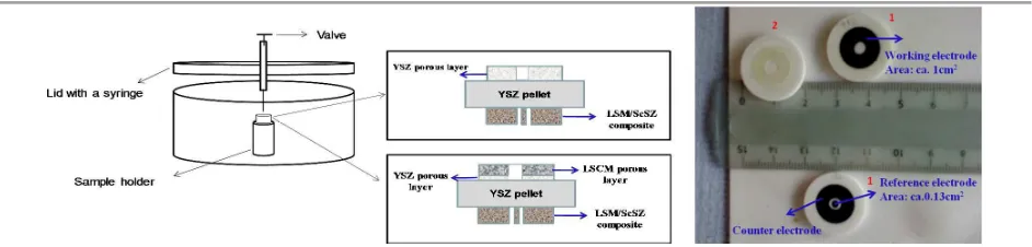
Figure. 1 Schematic representation of a home-made setup for wet vacuum impregnation and sample SOECs prepared by vacuum impregnation and an image of the freshly made GDC impregnated LSCM cathode cell (No. 1) and GDC impregnated YSZ cathode cell (No. 2)
temperature fabrication.[17-18] Wet impregnation is a frequently used technique in SOFC to obtain high electrode activities. [19] Attempts to seek cathode materials that can compete with Ni towards steam and CO2 electrolysis were also reported using the impregnation technique; [20-23] however, this has not been fully successful. Gorte et al reported an excellent electrode with 0.5wt% Pd, 5wt% Ce0.48Zr0.48Y0.04O2, and 45wt% LSCM infiltrated into YSZ
scaffold which performed better than Ni-YSZ cermet in fuel cell operation, however, the comparison in electrolyser mode was not available, nor the stability of the system in CO2-CO mixture.
[20] K. Xie et al successively investigated LSCM based electrode impregnated with V2O5 and Ni for CO2 and steam electrolysis, but the reported
Faradaic efficiencies were not satisfying with the durability being another concern, especially with Ni.[21-22] Cu was also studied to provide electronic conductivity and catalytic activity in the aid of LSCM electrode for H2O-CO2 co-electrolysis, yet the system suffered from increased resistance with increasing CO2 feed. [23] Due to the low melting temperature of Cu, stability of the Cu-LSCM material is again an issue. Efforts here will be made to modify the LSCM/GDC cathode fabrication procedures, aiming to enhance its performance for CO2 dissociation to a comparable level to Ni-cermet, by means
of vacuum impregnation. The microstructure and performance of the impregnation-derived cathode will be characterized and compared with the counterpart cathode prepared from screen-printing. A durability study will be carried out on the impregnation-derived LSCM-GDC cathode in CO2-CO mixture for high temperature
CO2 electrolysis.
2.
Experimental
2.1 Single cell fabrication
The SOECs prepared were with three-electrode configuration. The cathode of interest, fabricated by various procedures, was on one side of YSZ electrolyte as working electrode whereas, the LSM-ScSZ (scandium stabilised zirconia) composite was screen-printed on the other side of electrolyte as both counter and reference electrode, and the electrochemical contribution of the LSM-ScSZ oxygen electrode is revealed in Figure S1. The initial fabrication steps involved the preparation of YSZ pellets, YSZ and LSCM ((La0.75Sr0.25)0.97Cr0.5Mn0.5O3±δ)
screen-printing inks and GDC (Gd0.1Ce0.9O1.95) nitrate solution. The YSZ screen-printing ink was prepared by mixing the oxide powder,
dispersant and organic binders via ball milling with spherical zirconia grinding media (8mm in diameter). Glassy carbon and graphite, with a ratio of 20:80, were used as pore formers. The amount of pore formers was 30 wt%, lower than which did not give a sufficiently porous layer for subsequent infiltration and higher than which made the YSZ ink too thick to be printed on the surface of YSZ electrolyte. The LSCM ink was prepared in a similar fashion. The as-prepared YSZ ink was printed on the dense YSZ pellet, followed by printing a relatively thick LSCM porous layer on top and co-firing these two layers at 1300oC. GDC nitrate solution (2M) was prepared, for which Gd(NO3)3∙6H2O (Aldirch) and Ce(NO3)3∙6H2O (Fisher Scientific)
nitrates in stoichiometric ratio were dissolved into distilled water. The following steps were adding GDC aqueous nitrate solution into LSCM/YSZ porous layers in vacuum condition (0.22bar) and heat treatment at 500oC to decompose nitrates. The impregnation was carried out in a home-built vessel with pressure control, as illustrated in Figure 1. The impregnation steps were repeated until the GDC loading reached 50% with respect to the weight of LSCM/YSZ bilayers. Finally, the sample was calcined at 1100oC, and LSM-ScSZ positive electrode was printed and fired at 1100oC afterwards.
An SOEC with GDC impregnated YSZ cathode was also fabricated by infiltrating GDC nitrate solution into a solely YSZ porous skeleton, similar to the preparation of the GDC impregnated LSCM cathode. An image of the freshly made GDC impregnated LSCM cathode (Marked as No.1 in Fig. 1) and GDC impregnated YSZ cathode (Marked as No. 2 in Fig. 1) SOEC is presented in Fig. 1.
Dopant levels of Pd catalyst (0.5-1 wt%) were introduced into cathode by wet atmospheric impregnation and thermal treatment at 500oC after GDC impregnation, and comparisons were made to the cathode without Pd co-catalyst. In parallel, infiltration of Ni (1 wt%) or Pd (0.5 wt%) co-catalyst was conducted in a similar manner into the LSCM-GDC (weight ratio 50-50) composite cathode manufactured via screen-printing and high temperature sintering (at 1200-1300oC), in order to screen the cathode material with the highest performance towards CO2 electrolysis.
2.2 Electrochemical characterization and post-mortem measurement
Pt paste and wires were fired at 900oC to function as current
Journal
of
Materials
Chemistry
A
Accepted
Manuscript
Journal Name
ARTICLE
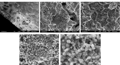
Figure. 2 Cross-sectional view (a, b and c) and surface view (d, e) of a freshly made GDC impregnated LSCM cathode applied in high temperature SOEC (a: cross-section of the whole cathode/electrolyte interface; b: the inner cathode, i.e the GDC impregnated YSZ zone; c: the outer cathode area, i.e. the GDC impregnated LSCM region; d: surface view of the GDC impregnated LSCM cathode; e: a close-up look of d.).
collectors before electrochemical characterizations. The testing set-up and gas flows used were explained elsewhere. [17]
Briefly, a gas mixture with different CO2-CO ratios
(controlled by mass flow controllers) at a flow rate of 30ml/min was used as fuel for CO2 electrolysis. Polarization curves and Ac-impedance spectra of the as-prepared SOECs were measured in CO2-CO mixtures from 900 to 750oC at an
interval of 50oC, using a ZAHNER IM6e Electrochemical Workstation. The scanning frequency in impedance measurement ranged from 105 to 0.1Hz at an amplitude of 20mV. Impedance comparisons were made between the LSCM/GDC cathodes manufactured via different approaches for CO2 electrolysis. Polarization resistance (Rp) from different
cathode was estimated from the values at lowest frequency and the intercept of the impedance arc with the real axis at high frequency. This was done as the impedance arc did not intersect with the real axis even at a frequency as low as 0.015Hz and there was no extra arc due to the downward tendency of the low frequency arc as frequency decreased. A stability test on the 0.5wt%Pd and GDC co-impregnated LSCM cathode working in CO2-CO 50-50 mixture for CO2
electrolysis was carried out by recording the voltage variations as a function of operating time at a constant current density of -0.15 Acm-2 at 900oC, and the impedance responses before and after the stability test were recorded.
Scanning electron microscopy (SEM) was employed to study the microstructure of the GDC impregnated LSCM cathode before and after electrochemical characterization, and the
equipment used were Jeol JSM 5600 (with tungsten filament) and Jeol JSM-6700F (with field emission gun). The energy-dispersive X-ray spectroscopy (EDX) was incorporated for element identification, and an Oxford INCA Energy 2000 device was coupled with SEM instrument for this purpose.
3.
Results and discussion
3.1 Microstructure of the GDC impregnated LSCM cathode
Figure 2 shows the SEM images of a freshly made GDC impregnated LSCM cathode. From the cross-section view (Fig. 2(a)), it can be seen that a fairly good cathode/electrolyte interface is obtained due to the introduction of a porous YSZ layer between electrolyte and the bulk cathode. A total thickness of 60-70μm is identified for the cathode, with ~20μm for porous YSZ layer and ~40μm for porous LSCM layer (confirmed by EDX). For this cathode, it is the large sized LSCM particles, and/or the YSZ particles in the region close to the dense YSZ electrolyte, serve as the backbone for cathode. In Fig. 2(b) and (c), it is clear that the infiltrated GDC particles are highly dispersed on the surface of LSCM/YSZ skeleton with GDC particles sized at ~ 50-100 nm. It is noteworthy from Fig. 2 (b) and (c) that the morphology of the GDC coatings over YSZ and LSCM seem different. The GDC particles are well interconnected with each other on YSZ surfaces, whereas they are rather scattered over the LSCM. Gorte et al reported the interfacial interactions between ceria and YSZ in a similar structure (i.e. ceria coated porous YSZ substrate) and the
Journal
of
Materials
Chemistry
A
Accepted
Manuscript
Figure 3. Polarization curves (a) and the Tafel-plots (b) of a SOEC with the GDC impregnated LSCM cathode operating in CO2-CO mixtures at 900oC. The inset in (b) is the comparison of ASR (values calculated from Tafel plot) between SOEC and SOFC operations at an overpotential of 0.5V.
Figure 4. (a) Nyquist plots and (b) Bode plots of the impedance data from the GDC impregnated LSCM cathode working under OCV at 900oC in CO2-CO mixtures. considerable mobility of ceria films over YSZ as a function of
temperature and reducing/oxidizing environment. [24-25] The discrete distribution of GDC particles over LSCM is more notable from the surface view in Fig. 2 (d) and (e), where the GDC nano-particles locate on the surface of the cathode backbone in a high dispersion. And impressively, the highly dispersed GDC particles bridge the large LSCM particles, which are believed to be ideal for expanding surface areas and providing extra active sites for cathode reaction. The impregnation-derived cathode is thus advantageous for extending triple phase boundaries and boosting the cathode electrochemical activity.
The cathode microstructure revealed in Fig. 2 is significantly different from those prepared via screen-printing. [17] The wet impregnation gives more flexibility for optimising the electrode microstructure in SOFCs/SOECs, as the electrode components can be added separately and fired at different temperatures to tune their properties according to their functions.Here, the vacuum impregnation enables the addition of a large amount of highly active GDC into cathode substrate and the uniform
distribution of the infiltrated GDC phase (confirmed by EDX), without sacrificing the electrolyte/cathode interfacial contacting, as encountered in the cathode prepared from the traditional ceramic mixing method, e. g., screen-printing.
3.2 High temperature CO2 electrolysis performance of the
impregnation-induced cathode
The GDC impregnated LSCM cathode.Figure 3 and 4 display the electrochemical results of the GDC impregnated LSCM cathode SOEC working in various CO2-CO mixtures at 900
o
C. In Fig. 3(a), a fairly linear relation between potential and current density can be seen. Due to the employment of a 2mm thick YSZ electrolyte, it is expected that the ohmic resistance (Rs) would be the dominant limitation for the cell performance. Also in Fig. 3(a), only marginal difference in performance is observed on the cell working in varying CO2-CO mixtures. A similar phenomenon is noticed from Fig. 3(b), in which the Tafel-like behaviour is shown for the cell overpotential vs. logarithm of current density. An increase in CO2 concentration from 50% to
90% does not impact the polarization losses in operational
Journal
of
Materials
Chemistry
A
Accepted
Manuscript
Journal Name
ARTICLE
Table 1. Comparisons between theoretical and measured OCV values from a three-electrode SOEC with the GDC impregnated LSCM cathode working in CO2-CO mixtures at 900oC.
OCV (V)
Theoretical value Measured value
CO2-CO 90-10 0.785 0.784
CO2-CO 70-30 0.853 0.848
CO2-CO 50-50 0.896 0.891
Figure 5. Polarisation curves (a) and impedance spectra (b) of the SOEC with the GDC infiltrated LSCM cathode working in CO2-CO 70-30 atmosphere at temperature ranging from 900oC to 750oC at an interval of around 50oC.
conditions for the GDC/LSCM cathode fabricated via vacuum impregnation, meaning that it is able to work in a wide range of CO2-CO ratios without affecting its output significantly in
CO2 electrolysis.
Great asymmetry in polarization behaviour is found for CO oxidation and CO2 reduction reaction from the infiltration
derived GDC/LSCM electrode in Fig. 3(b). At a potential of 0.5V (vs OCV) at 900oC, the area specific resistance (ASR) is 3.85, 3.70, and 3.64 Ω cm2 for CO2 reduction in CO2 concentration of
90%, 70%, and 50% respectively, whilst it is 4.09, 3.75, and 3.66 Ω cm2 for CO oxidation. These suggest a higher performance in SOEC than in SOFC operation from the impregnation derived GDC/LSCM electrode. P. Kim-Lohsoontorn et al. reported a similar trend from Ni-GDC cathode used for steam electrolysis, stressing that ceria-based electrode favours operation in electrolysis mode.[26-27] Consistent result was also reported on La0.35Sr0.65TiO3-δ
-Ce0.5La0.5O1.75-δ electrode at 800 o
C in H2-H2O atmospheres.
[28]
Noting the difference between the ASR from SOEC and that from SOFC in 90% CO2 is more distinct than in lower CO2
concentrations, which indicates that the infiltration-originated GDC/LSCM cathode is beneficial for efficient electrolysis at CO2-rich fuels.
The open circuit voltage (OCV) values from the cell with the GDC impregnated LSCM cathode working in varying CO2-CO
atmospheres are shown in Table 1. These values were obtained from the three-electrode measurement; and they are very close to the theoretical values expected from the Nernst equation. In addition, the experimental OCV values in Table 1
are much higher than those obtained from the screen-printed
LSCM-GDC composite cathode in identical conditions, [17] which probably originates from the expanded reaction areas and the accelerated electrode kinetics from the optimised microstructure offered by vacuum impregnation of GDC into LSCM/YSZ scaffold.
The impedance results of the GDC impregnated LSCM cathode operated in CO2-CO mixtures at 900oC at OCV are
compared in Figure 4. The ohmic loss in Fig. 4(a) is significant, with a dominant contribution from the 2mm thick electrolyte applied in the present study and a minor lateral contribution from cathode due to the introduction of a porous YSZ interlayer. Optimisation in the thickness of the interlayer is thus necessary to minimize the cathode ohmic loss in future work. It can be seen from Fig. 4(a) that the Rs does not vary with gas compositions, whereas the Rp reduces against increasing CO concentration. These observations are similar to those found from the screen-printed LSCM-GDC cathode,[17-18] therefore, can be explained likewise by the reinforced electro-catalytic properties, such as oxide ion mobility and surface exchange rate, from LSCM-GDC composite in increasingly reducing atmosphere.
However, the impedance behaviour from the GDC impregnated LSCM cathode is in great contrast with those from the screen-printed LSCM-GDC counterpart in identical conditions. Instead of the Gerischer-like impedance dispersion from the latter,[18] two distinct arcs with the high frequency arcs overlapped in various atmospheres and the low frequency arc diminished against increasing CO concentration are seen from the former. This can be attributed to the microstructure diversities from the cathodes manufactured in different procedures, which affect their electrochemical behaviour accordingly. The Bode plots in Fig. 4(b) show that the characteristic frequencies are around 102 Hz and 1 Hz respectively for the high frequency and low frequency arc respectively for the infiltration derived GDC/LSCM cathode. The performance of the GDC impregnated LSCM cathode operated in CO2-CO 70-30 mixture during cooling from 900
o
C to 750oC is illustrated in Figure 5. In Fig. 5(a), it is observed that the polarization losses increase with lowering operation temperature, confirmed by the impedance spectra in Fig. 5(b)
Journal
of
Materials
Chemistry
A
Accepted
Manuscript
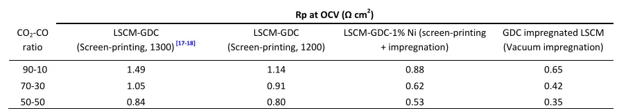
Table 3. Summary of Rp values from the different routes-induced LSCM/GDC cathode for CO2 electrolysis at 900oC in CO2-CO systems.
Rp at OCV (Ω cm2)
CO2-CO
ratio
LSCM-GDC (Screen-printing, 1300) [17-18]
LSCM-GDC (Screen-printing, 1200)
LSCM-GDC-1% Ni (screen-printing + impregnation)
GDC impregnated LSCM (Vacuum impregnation)
90-10 1.49 1.14 0.88 0.65
70-30 1.05 0.91 0.62 0.42
50-50 0.84 0.80 0.53 0.35
Table 2. ASR at an overpotential of 0.5V from electrolysis and fuel cell operations on the GDC impregnated LSCM cathode working in CO2-CO 70-30 at 900-750oC.
ASR at an overpotential of 0.5V (Ω cm2)
Temperature (o
C) Electrolysis mode Fuel cell mode
900 3.70 3.75
850 4.33 4.41
802 5.41 5.54
751 6.88 7.52
which sees enlarged impedance arcs and a decreasing characteristic frequency for the low frequency arc as a result of retarded surface kinetics with lowering temperature. The asymmetry in polarization losses from electrolysis mode and fuel cell mode is presented over the whole temperature range.
Table 2 shows the ASR values of the impregnation-produced LSCM/GDC cathode at 0.5V vs OCV for both electrolysis and fuel cell operation in CO2-CO 70-30 at different temperatures.
The trend that the impregnation derived electrode performs better in electrolysis than in fuel cell mode becomes more significant with declining temperature. At 750oC, the ASR at 0.5V is 6.88 Ω cm2 for CO2 reduction and 7.52 Ω cm2 for CO oxidation respectively. Besides, the polarization curves were recorded while scanning potential from OCV to 1.4V (vs OCV), then to -0.5V (vs OCV) and backwards to OCV finally. Clearly there are no hysteresis on the polarization curves in Fig. 3(a) and Fig. 5(a), indicating the stability of the GDC impregnated LSCM material in a wide range of operating conditions. To compare the performance of the LSCM/GDC composite fabricated via different procedures, the Rp values of each cathode working in the same conditions are summarized in
Table 3. Detailed CO2 electrolysis performance of the
screen-printed LSCM-GDC (fired at 1300oC) composite cathode has been reported in Ref 17-18. In Table 3, the Rp values of the LSCM-GDC composite manufactured by screen-printing decline slightly upon lowering sintering temperature from 1300oC to 1200oC, due to the mitigation in particle growth and agglomeration, and the Rp values decrease further against introducing 1wt% Ni co-catalyst. The introduction of 0.5wt% Pd to screen-printed LSCM-GDC composite displayed marginally smaller Rp compared to 1 wt% Ni analogy (results not included here). However, the decreases in Rp by lowering sintering temperature and introducing co-catalyst to screen-printed cathodes are limited. Also, the electrolyte/cathode interfaces deteriorated when sintering temperature dropped for screen-printed cathodes.
Such problems were prevented in the GDC/LSCM cathode prepared via vacuum impregnation, by which means the cathode components were introduced and fired separately at temperatures suitable for each of them. Meanwhile, the GDC impregnated LSCM cathode presents markedly smaller Rp values compared to the screen-printed cathodes in Table 3. The Rp values from the GDC impregnated LSCM cathode are 0.65, 0.42, and 0.35 Ω cm2 for CO2 electrochemical reduction
in CO2-CO 90-10, 70-30 and 50-50 fuels at OCV at 900 o
C respectively, more than two-fold smaller than those from the screen-printed LSCM-GDC composite cathode in the identical conditions. The extraordinary electro-catalytic activity of the GDC/LSCM cathode fabricated by vacuum impregnation is undoubtedly due to the modified microstructure featuring with nano-sized GDC particles in highly dispersion over the surface of the LSCM/YSZ backbone, which is desirable for increasing active reaction sites, extending the cathode TPBs and therefore promoting the cathode electrochemical properties. Additionally, the enhancement in GDC properties in an active SOEC operation such as CO2 reduction is
significant, especially when the material is in nano scale.[24, 29] Thiscan be verified by the increasingly reduced Rp values with increasing CO fraction, compared to screen-printed cathodes. LSCM is a p-type conductor and shows predominantly electronic conductivity, therefore, the addition of oxygen ion conducting phase, such as YSZ and/or GDC, would tremendously promote the ionic conductivity, and enhance cathode performance, which could be demonstrated by the overall reaction of CO2 electrochemical reduction expressed in
Equation (1) where
.., , and
stand for an oxygen
vacancy provided by electrolyte, free electron from cathode, and an oxygen ion in the YSZ electrolyte lattice, respectively.[30]
+ ..
+ 2=
+ (1)
+ ,
.. + 2 → + ,
(2)
+ ,.. + 2 → + , (3)
In LSCM-YSZ and LSCM-GDC composite cathodes, the CO2
electrochemical reduction could be realised through Equation (2) and (3) where ,
.. ,
, .. and
,
,
,
represent
oxygen vacancies supplied by YSZ/GDC phase and oxygen ions in YSZ/GDC lattice in composite cathode, respectively. Indicated by Equation (1-3), the active reaction area for CO2
reduction is significantly extended by adding the high oxygen ion conducting phase to LSCM, and this is particularly the case when the introduced phase is in nano-sized particles as in the
Journal
of
Materials
Chemistry
A
Accepted
Manuscript
[image:7.612.81.539.613.692.2]Journal Name
ARTICLE
Figure 7. (a) Nyquist and (b) Bode impedance of impregnation derived GDC/LSCM cathode with and without Pd operating in CO2-CO 70-30 at OCV at 900oC.
Figure 6. Comparison between the GDC impregnated LSCM and the GDC impregnated YSZ negative electrode for SOEC working in CO2-CO 70-30 at OCV at 900oC. Note the Rs was subtracted assuming its similar contributions for both cells.
GDC impregnated LSCM cathode investigated here.
Doped ceria is a well-known mixed electronic and ionic conductor, and it possesses good catalytic properties towards a lot of oxidation/reduction reactions.[28, 31-35] To clarify the roles of LSCM and GDC on the impregnation-induced cathode, an impedance comparison was performed on the GDC infiltrated LSCM cathode and the GDC impregnated YSZ cathode operating at 900oC in CO2-CO 70-30 mixture, as
exhibited in Figure 6. Both cathodes present two distinguishable impedance arcs, yet the arcs from the GDC/LSCM cathode are clearly smaller than those from the GDC/YSZ set. As a result, it is the synergistic contributions from both components, i.e. the GDC nanoparticles and the LSCM phase that account for the outstanding performance from the GDC infiltrated LSCM cathode towards CO2 electrolysis via
SOEC. Oxygen vacancies have been reported to be beneficial for not only the mobility of oxygen ions, but also the favourable accommodation of CO2 chemical adsorption. [36-37] This can interpret the catalytic contributions from LSCM phase in SOEC operation, based on the fact that the charge compensation as a result of the substitution of Sr into the A-site of LSCM perovskite is achieved by the formation of oxygen vacancies rather the transition of Cr3+/Mn3+ to Cr4+/Mn4+ at low oxygen partial pressure (i.e. at high CO concentrations). [38]
GDC impregnated LSCM cathode with Pd co-catalyst.
Transition metals, such as Ni, Fe, Cu, Pt, Pd etc., have been reported to be essential for electrode catalytic properties improvement in SOFC applications.[35, 39-42] It also has been found in previous section that the introduction of Ni/Pd co-catalyst appreciably improved the catalytic properties of the cathode prepared by screen-printing. In this part, 0.5-1wt% Pd was added to the GDC impregnated LSCM cathode by atmospheric impregnation to further enhance the cathode activity. The performance of the Pd and GDC co-impregnated LSCM cathode for CO2 electrolysis in CO2-CO 70-30 at 900
o
C is displayed in Figure 7, in comparison to the cathode without Pd. As expected, the addition of Pd co-catalyst notably diminishes the impedance arcs of the GDC infiltrated LSCM cathode in Fig. 7(a), compared to the cathode without Pd. This means that the cathode properties towards CO2 electrolysis are more intensified by the aid of Pd co-catalyst. In Fig. 7(a),
the smallest Rp, i.e. the highest performance, occurs on the cathode with 0.5wt% Pd, and increasing Pd loading to 1wt% does not provide further improvement in cathode activity. The introduction of Pd co-catalyst substantially decreases the low frequency arc of the GDC infiltrated LSCM cathode, meaning the relevant processes, e.g. the surface exchange and diffusion of reactant species, are facilitated with adding Pd co-catalyst. Furthermore, a characteristic frequency value of 18.6 and 3.39Hz was presented in Fig. 7(b) for the low frequency arc from the 0.5wt% and 1wt% Pd assisted GDC coated LSCM cathode, respectively, whereas a corresponding value of 1.43Hz is seen on the cathode without Pd. The higher summit frequencies observed again can be attributed to the accelerated surface kinetics, as a result of adding Pd co-catalyst.
Y. Ye and S. Jiang et al investigated the Pd impregnated LSCM-YSZ composite anode in methane fuelled SOFCs, and found the Rp associated with the low frequency arc decreased upon adding Pd. [43] The enhancing effect of Pd on the surface exchange and diffusion was proposed to be related to the co-existence of Pd and Pd/PdOx on the anode surface, favoured
by the presence of water, leading to accelerated oxygen species diffusion in LSCM-YSZ composite. Similarly, the formation of Pd/PdOx is possibly promoted by the appearance of CO2 in our study, resulting in the boosted cathode catalytic
properties for CO2 electrolysis consequently. However, the
Pd/PdOx, formed as a result of the interaction between
LSCM/GDC and Pd, is a semiconductor which may impact the
electrode conductivity adversely. This might explain the
Journal
of
Materials
Chemistry
A
Accepted
Manuscript
Figure 8. Results from the 0.5 wt% Pd-GDC co-impregnated LSCM cathode SOEC working in CO2-CO 50-50 atmosphere at 900oC for CO2 electrolysis with (a) cell potential vs. time at a constant current density of -0.15 Acm-2 in a galvanostatic operation and (b) cathode impedance comparison at the beginning and the end of stability measurement at -0.15 Acm-2.
Table 4. Comparison of Rp values from different SOEC cathodes working in CO2-CO atmospheres at OCV at 900oC.
CO2-CO ratio Ni-YSZ
[17]
0.5Pd-GDC co-impregnated LSCM
90-10 0.33 0.34
70-30 0.23 0.24
50-50 0.24 0.22
enlarged impedance from the 1.0wt% Pd-GDC co-infiltrated LSCM cathode compared to the counterpart with less Pd. The Rp values from the 0.5wt% Pd and GDC co-infiltrated LSCM cathode working in varying CO2-CO atmospheres at
900oC at OCV are listed in Table 4, together with those from the conventional Ni-YSZ cermet cathode working in identical conditions. The detailed electrochemical performance of Ni-YSZ cermet cathode towards high temperature CO2 electrolysis was covered in Ref 17. Notably, with the introduction of 0.5wt% Pd co-catalyst, the cathode performance of the GDC impregnated LSCM material is doubled compared to that without Pd revealed in Table 3. In Table 4, the 0.5wt% Pd and GDC penetrated LSCM cathode exhibits competitive Rp values with those from a well-behaved state-of-the-art Ni-YSZ cermet cathode under the same conditions. Yet unlike Ni-YSZ, both LSCM and GDC are considered excellent carbon resistant materials,[32, 38, 42 and 44] therefore, the Pd-GDC co-impregnated LSCM material can be regarded as a promising alternative
cathode in the application of high temperature CO2
electrolysis.
3.3 Durability of the GDC impregnated LSCM cathode for CO2 electrolysis via SOEC
The durability of the 0.5wt% Pd and GDC co-infiltrated LSCM material was evaluated at a constant current density, -0.15A cm-2, in CO2-CO 50-50 at 900oC for a period of time, during
which the variation in cell potential was recorded.Figure 8(a) exhibits the cell voltage evolution as a function of operating time. The initial voltage fluctuation observed in Fig. 8(a) is due to the switching of fuel gas from H2O-H2-CO2-CO to CO2-CO
mixture, which will be explained in the following part. Apart from that, there are hardly any degradations during 23hrs’ operation. The impedance spectra of the 0.5wt% Pd and GDC co-impregnated LSCM cathode were recorded before and after the stability test at-0.15A cm-2, as shown in Figure 8(b). Apparently, the impedance spectra almost overlap and no difference can be seen before and after the durability test. This is consistent with the observations in Fig. 8(a), suggesting a fairly stable performance from the 0.5wt% Pd and GDC co-impregnated cathode operating in CO2-CO 50-50 mixture.
It should be mentioned that before switching to CO2-CO
mixture, the Pd-GDC co-impregnated LSCM cathode was run in H2O-H2-CO2-CO systems for steam-carbon dioxide
co-electrolysis for ca. 140hrs, during which evident increase in Rs (from 3.75 to 4.05 Ω cm2) with slight increase in low frequency arc was found (results shown in Figure S2). An obvious increase in Rs with unchanged Rp was also reported previously from screen-printed LSCM-GDC cathode operated in CO2-CO
system for ~200hrs at -0.25A cm-2, caused by the deterioration in the interface between cathode and Pt current collector. [17] Similarly, the degradation in current collector is probably the main reason for the apparent increase in Rs during co-electrolysis, besides the possible increase in cathode lateral resistance due to agglomerations in GDC nanoparticles. A cell potential decay from initially 1.525V to 1.585V happened during co-electrolysis operation. However, the potential recovered back to 1.54V upon switching to CO2 electrolysis.
Corresponding impedance measurements saw a slight decrease in Rs upon the switching. It has been reported that the appearance of moisture in air negatively impacted the stability of the (La,Sr)MnO3 (LSM) material in SOFC operation,
resulted from a possible enhancement in removal of manganese from LSM/YSZ interfaces when humidity was introduced.[45-46] The presence of steam may affect the property of LSCM in a similar manner as in LSM, however, this is not in the scope of the present study.
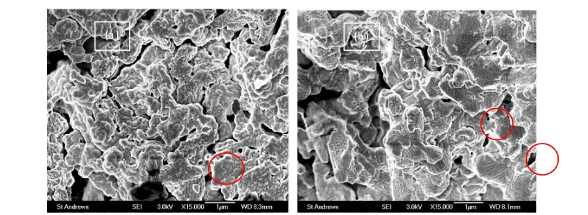
The microstructure of the 0.5%Pd-GDC penetrated LSCM cathode was examined after durability test, shown in Figure 9. A good cathode/electrolyte interface is sustained after stability test. From the inner cathode area where the cathode composition is Pd-GDC infiltrated YSZ (Fig. 9(a)), different morphology can be seen in contrast to the fresh cathode (shown in Fig. 2(b)). There are slight agglomerations and growth in the nano particles after prolonged operation. Similar observations can be seen from the outer cathode area (Fig.
Journal
of
Materials
Chemistry
A
Accepted
Manuscript
Journal Name
ARTICLE
Figure 9. SEM images of the cross-sectional view of the 0.5% Pd and GDC co-impregnated LSCM cathode after durability test with (a) the inner side area, i.e. GDC impregnated YSZ layer, and (b) the outside area, i.e. GDC impregnated LSCM layer. The highlighted areas in (a) and (b) shows observable features in contrast to those in Fig. (b) and (c) respectively.
9(b)), i.e. the Pd- GDC impregnated LSCM layer, except that the particle size growth is less apparent compared to that in the inner cathode. The morphology of ceria when in contact with YSZ substrate has been reported to be sensitive to the environment to which ceria was exposed, and restructuring was observed from ceria films in intimate contact with YSZ upon annealing under different conditions. [24-25, 33] The contrast in the inner cathode area from the Pd-GDC impregnated LSCM material before and after durability test may be understood, as the cathode underwent complex fuel compositions in the co-electrolysis and CO2 electrolysis
stability measurement. The microstructure variations in the GDC infiltrated LSCM layer (the outer cathode area) suggest that the interaction between GDC nanoparticles and LSCM backbone might play a role different from that between GDC and YSZ backbone, which will be studied in the future. Despite the microstructure changes and increased Rs values after stability test, the 0.5wt% Pd-GDC penetrated LSCM cathode exhibited a Rp of 0.25 Ωcm2 in CO2-CO 50-50 mixture
at 900oC (Fig. 8(b)), the same magnitude as the value before the prolonged operation for co-electrolysis and CO2
electrolysis (Table 4), which again indicates its promise in the application of CO2 electrochemical reduction through SOECs.
4.
Conclusions
Impregnation strategy was applied in this work to tailor the microstructure and therefore to enhance the performance of the LSCM-GDC cathode material in SOECs used for high temperature CO2 electrolysis. A high performance and durable
cathode material for CO2 electrolysis was realized by vacuum
impregnation of GDC into a two-layered LSCM and YSZ skeleton, which gave excellent electrochemical performance and durability in CO2-CO mixture. The modified microstructure from the GDC/LSCM electrode fabricated via vacuum impregnation featured highly dispersed GDC nano-particles over the porous LSCM and YSZ skeleton. The incorporation of the porous YSZ layer between the electrolyte and LSCM layer
avoided the deterioration of cathode/electrolyte interface. Vacuum impregnation offered an effective means to introduce electrochemical and catalytic active component in the form of nano-particles, especially when larger amounts of catalyst were desired.
The impregnation derived GDC/LSCM cathode afforded a facile CO2 electrochemical reduction process, compared to the
screen-printed LSCM-GDC cathode. The Rp from the GDC impregnated LSCM cathode for the CO2 electrolysis reached
0.42 Ωcm2at OCV at 900oC in CO2-CO 70-30 mixture, more
than two-fold smaller than the value from the screen-printed counterpart operated in identical conditions. The superior performance from the impregnation-derived GDC/LSCM cathode was believed to be associated with the enhanced electrochemical and catalytic activity from the nano-structured GDC phase and the synergistic electro-catalytic properties from the LSCM phase besides GDC nanoparticles. Moreover, the infiltration introduced GDC/LSCM material performed better for CO2 reduction than CO oxidation in the device as a
solid oxide cell, especially in CO2-rich environment.
A comparable cathode activity with a well-behaved Ni-YSZ cermet cathodes was achieved on the 0.5wt% Pd and GDC co-impregnated LSCM material, which exhibited an Rp of 0.22 Ω cm2at OCV at 900oC in CO2-CO 70-30 mixture. Durability study
of the Pd-GDC co-infiltrated LSCM cathode in CO2 electrolysis at a constant current density of -0.15A cm-2 presented a stable potential over a period of ~23 hrs at 900oC in CO2-CO 50-50
mixture. Although slight agglomerations were observed, the cathode Rp did not change much after prolonged operation in H2O-H2-CO2-CO as well as CO2-CO mixtures. The Pd-GDC
infiltrated LSCM material can thus be considered as a potential cathode for high temperature CO2 electrolysis and H2O-CO2
co-electrolysis.
Acknowledgements
This work was funded by Overseas Research Students Awards Scheme (ORSAS), University of St Andrews and by RCUK Energy
Journal
of
Materials
Chemistry
A
Accepted
Manuscript
Supergen programme on H-Delivery and EPSRC Platform and Senior fellowship programs (EP/G01244X/1). JTSI acknowledges the Wolfson Research Merit Award (WRMA 2012/R2).
References
1 Z. Zhan, W. Kobsiriphat, J. R. Wilson, M. Pillai, I. Kim, and S. A. Barnett, Energy Fuels, 2009, 23, 3089.
2 H. Yano, F. Shirai, M. Nakayama, K. Ogura, J. Electroanal.
Chem., 2002, 533, 113.
3 K. Hara, A. Kudo, T. Sakata, J. Electroanal. Chem., 1995, 391, 141.
4 T. Yamamoto, D. A. Tryk, A. Fujishima, H. Ohata,
Electrochem. Acta, 2002, 47, 3327.
5 D. W. DeWulf, T. Jin, and A. J. Bard, J. Electrochem. Soc., 1989, 136, 1686.
6 Y. Hori, H. Wakebe, T. Tsukamoto and O. Koga, Electrochim. Acta, 1994, 39, 1833.
7 S. R. Narayanan, B. Haines, J. Soler, and T. I. Valdez, J.
Electrochem. Soc., 2011, 158, A167.
8 Y. Chen and M. W. Kanan, J. Am. Chem. Soc., 2012, 134, 1986.
9 G. Centi, S. Perathoner, Catal. Today, 2009, 148, 191. 10 S. D. Ebbesen, M. Mogensen, J. Power Sources, 2009, 193,
349.
11 C. Graves, S. D. Ebbesen, M. Mogensen, K. S. Lackner, Renew. Sust. Energy Rev., 2011, 15, 1.
12 A. O. Isenberg, Solid State Ionics, 1981, 3/4, 431.
13 Y. Jiang and A. Virkar, J. Electrochem. Soc., 2003, 150, A942. 14 Y. Matsuzaki and I. Yasuda, J. Electrochem. Soc., 2000, 147,
1630.
15 J. Koh, Y. Yoo, J. Park, H. C. Lim, Solid State Ionics, 2002, 49, 157.
16 P. Holtappels, L. G. J. de Haart, U. Stimming, I. C. Vinke, and M. Mogensen, J. Appl. Electrochem., 1999, 29, 561.
17 X. Yue and J. T. S. Irvine, J. Electrochem. Soc., 2012, 159, F442.
18 X. Yue and J. T. S. Irvine, Electrochem. Solid-State Lett., 2012,
15, B31.
19 S. Jiang, Mater. Sci. Eng. A, 2006, 418, 199.
20 F. Bidrawn, G. Kim, G. Corre, J. T. S. Irvine, J. M. Vohs, and R. J. Gorte, Electrochem. Solid-State Lett., 2008, 11, B167. 21 Y. Li, Y. Gan, Y. Wang, K. Xie, and Y. Wu, Int. J. Hydrogen
Energy, 2013, 38, 10196.
22 X. Zhang, L. Ye, J. Ju, J. Li, W. Jiang, C. Tseng, and K. Xie,
Electrochem. Acta, 2016, 212, 32.
23 R. Xing, Y. Wang, Y. Zhu, S. Liu, C. Jin, J. Power Sources, 2015,
274, 260.
24 G. Kim, J. M. Vohs and R. J. Gorte, J. Mater. Chem., 2008, 18, 2386.
25 O. Costa-Nunes, R. J. Gorte and J. M. Vohs, J. Mater. Chem., 2005, 15, 1520.
26 P. Kim-Lohsoontorn, N. Laosiripojana, J. Bae, Curr. Appl.
Phys., 2008, 11, S223.
27 P. Kim-Lohsoontorn, J. Bae, J. Power Sources, 2011, 196, 7161.
28 O. A. Marina, L. R. Pederson, M. C. Williams, G. W. Coffey, K. D. Meinhardt, C. D. Nguyen, and E. C. Thomsen, J.
Electrochem. Soc., 2007, 154, B452.
29 K. Chen, N. Ai, and S. Jiang, J. Electrochem. Soc., 2010, 157, P89.
30 G. Tao, K. R. Sridhar, C. L. Chan, Solid State Ionics, 2004, 175, 615.
31 J. Kaspar, P. Fornasiero, M. Graziani, Catal. Today, 1999, 50, 285.
32 R. J. Gorte, S. Park, J. M. Vohs and C. Wang, Adv. Mater., 2000, 12, 1465.
33 E.S. Putna, T. Bunluesin, X. L. Fan, R. J. Gorte, J. M. Vohs, R. E. Lakis, T. Egami, Catal. Today, 1999, 50, 343.
34 R. D. Green, C. Liu, S. B. Adler, Solid State Ionics, 2008, 179, 647.
35 M. D. Gross, J. M. Vohs, and R. J. Gorte, J. Electrochem. Soc., 2007, 154, B694.
36 Y. Zhang, J. Li, Y. Sun, B. Hua, and J. Luo, ACS Appl. Mater.
Interfaces, 2016, 8, 6457.
37 W. Qi, Y. Gan, D. Yin, Z. Li, G. Wu, K. Xie, and Y. Wu, J. Mater.
Chem. A, 2014, 2, 6904.
38 S. Tao and J. T. S. Irvine, J. Electrochem. Soc., 2004, 151, A252.
39 G. Kim, S. Lee, J. Y. Shin, G. Corre, J. T. S. Irvine, J. M. Vohs, and R. J. Gorte, Electrochem. Solid-State Lett., 2009, 12, B48. 40 J. Kim, V. V. Nair, J. M. Vohs, and R. J. Gorte, Scripta Mat.,
2011, 65, 90.
41 A. Babaei, S. Jiang, and J. Li, J. Eletrochem. Soc., 2009, 156, B1022.
42 S. Jiang, X. Chen, S. H. Chan, and J. T. Kwok, J. Electrochem. Soc., 2006, 153, A850.
43 Y. Ye, T. He, Y. Li, E. H. Tang, T. L. Reitz, and S. Jiang, J.
Electrochem. Soc., 2008, 155, B811.
44 X. C. Lu, J. H. Zhu, Solid State Ionics, 2007, 178, 1467. 45 J. Nielsen, A. Hagen, Y. L. Liu, Solid State Ionics, 2010, 181,
517.
46 J. Nielsen, M. Mogensen, Solid State Ionics, 2011, 189, 74.