Accurate high-resolution 3D surface
reconstruction and localisation using a
wide-angle flat port underwater stereo
camera
Towards autonomous ship hull inspection
Robert Schattschneider
A thesis submitted in partial fulfilment of the requirements for the Degree of
Doctor of Philosophy
University of Canterbury, Christchurch, New Zealand
2014
Abstract
The goal of this thesis is to scan a ship hull with high 3D accuracy and resolution using an underwater stereo camera so as to enable the future autonomous detection of invasive biofouling organisms with autonomous underwater vehicles (AUVs). However, turbidity in most harbours necessitates being within a metre of the hull and thus requires ultra wide-angle camera lenses. But such ultra wide-wide-angle lenses embedded in an underwater housing with a flat port lead to significant distance dependent image distortions. Prior research in this area has only considered narrower fields of view and so has not solved for the significant image distortions arising from wide-angle high resolution flat port underwater cameras. This thesis proposes a solution to modelling and calibrating the underwater camera for accurate 2D imaging and 3D reconstruction, and additionally demonstrates an accurate underwater real-time pose estimation system required for future ship hull relative AUV navigation.
In this thesis an ultra wide-angle, short-baseline stereo camera is used, which is embedded in a flat port underwater housing. Flat port underwater housings represent a cost efficient way to use arbitrary in-air cameras underwater. However, the flat port of the underwater housing is subject to light refraction and causes distance dependent distortion, which is particularly visible at the large angles of the ultra wide-angle stereo camera used. To incorporate the effects of refraction, the thesis uses the well-known and accurate physics-based refractive underwater camera model. In contrast to the perspective camera-based underwater camera model, the refractive underwater camera model accurately describes the distance dependency of distortion. In the beginning of this thesis, the effects of refraction caused by a thick flat port underwater housing are summarised and extended. In this context, the fundamental magnification function is proposed, which enables the description of numerous known and also newly discovered effects. An additional quantitative analysis is carried out in which the importance to model the thickness of the port and the wavelength of light is revealed.
The thesis also investigates the impact of the port and the impact of the indices of refraction on the camera’s projection and reconstruction accuracy. A novel investigation shows that the water pressure, water salinity, water temperature, air pressure and the wavelength of light significantly affect the projection and reconstruction accuracy of wide-angle flat port underwater stereo cameras and should not be neglected by standard refractive indices.
Moreover, this thesis proposes an accurate and efficient calibration method for thick flat port underwater stereo cameras. The proposed calibration method mainly achieves its high accuracy by the use of a significantly higher number of calibration images. In contrast to prior research, the computation of the reprojection error does not represent a bottleneck if the proposed refractive forward projection method is used. In this way, the calibration is similar to standard in-air camera calibration techniques and minimises the reprojection error.
In combination with the proposed more accurate indices of refraction and refractive cal-ibration, the underwater reconstruction accuracy of the novel configuration of a wide-angle flat port underwater short baseline stereo camera is evaluated under real-world conditions. In this context, a method is proposed, which enables the evaluation of the accuracy of the reconstructed 3D object space.
Both chromatic aberration and pincushion distortion are effects of refraction and are par-ticularly visible at the large angles of wide-angle underwater cameras. In order to obtained distortion-free images with minimised chromatic aberration to texturize reconstructed 3D ship hull surfaces, this thesis proposes accurate real-time methods to minimise chromatic aberration and to correct the distortion in the underwater camera images.
The refractive camera model is based on image coordinates of images, which are distortion-free in air. But these in-air undistorted images are strongly distorted in-water by refraction, particularly at the large angles of wide-angle flat port underwater cameras. Image correspon-dence in these images is difficult. For that reason, this thesis proposes pseudo rectified images in which these distortions are minimised. Moreover, an accurate and efficient representation of epipolar curves is presented, which enables, for example, real-time constrained correspondence search or dense stereo.
Acknowledgements
I would like to thank the University of Canterbury, the Department of Mechanical En-gineering and the Department of Computer Science and Software EnEn-gineering, which made my research for this PhD possible. I thank the University of Canterbury for the UC Doctoral Scholarship.
I also would like to thank the university for the technical equipment and the helpful support by the technicians, which all helped to make this research possible.
Moreover, I would also like to thank New Zealand and its people for the personal expe-riences in a new country and culture.
I especially thank my supervisor Dr Richard Green for the outstanding support during the last years. His excellent expertise, personal commitment, and valuable discussions strongly contributed to the quality of this thesis.
Contents
Acronyms xv
Notations xvii
1. Introduction 1
1.1. Autonomous ship hull inspection for the detection of invasive marine species 1
1.2. Thesis overview . . . 3
1.3. Research contributions . . . 5
2. Underwater positioning and mapping for ship hull inspection 9 2.1. Underwater positioning and mapping sensor technologies . . . 9
2.1.1. Compass . . . 9
2.1.2. Depth sensor . . . 9
2.1.3. IMU . . . 10
2.1.4. Sonar-based systems . . . 11
2.1.4.1. Underwater acoustic positioning system . . . 11
2.1.4.2. Doppler Velocity Log . . . 12
2.1.4.3. Imaging sonars . . . 12
2.1.5. Vision-based systems . . . 13
2.1.5.1. Monocular and stereo cameras . . . 13
2.1.5.2. Structured light, Time-of-flight and Lidar . . . 13
2.1.6. SLAM . . . 15
2.2. Ship hull inspection systems . . . 15
2.2.1. Underwater vehicles . . . 15
2.2.2. Sonar-based ship hull inspection . . . 16
2.2.2.1. AquaMap Shiphull . . . 16
2.2.2.2. Hovering AUV . . . 17
2.3. Related vision-based projects . . . 20
2.3.1. Damn inspection . . . 20
2.3.2. Reconstruction of a sunken barge . . . 22
2.4. Proposed system design . . . 22
2.4.1. Wide-angle flat port underwater stereo camera . . . 22
2.4.2. Discussion of the terms wide-angle and ultra wide-angle . . . 24
3. Front port systems and wet-lenses 27 3.1. Introduction . . . 27
3.2. Flat port . . . 27
3.3. Dome port . . . 28
3.4. Ivanoff Corrector . . . 29
3.5. Wet lenses . . . 29
4. Effects of refraction 31 4.1. Introduction . . . 31
4.2. Related literature . . . 31
4.3. Proposed visualisation and clarifications of background literature . . . 34
4.4. Proposed refractive magnification function for the analysis of refraction . 37 4.4.1. Newly discovered properties and methods . . . 38
4.4.2. Proposed extensions of the radial distortion correction function for arbitrary thick ports . . . 38
4.4.3. Existing properties and methods . . . 39
4.4.4. Derivation of the refractive magnification function . . . 39
4.5. Newly observed and extended characteristics of refractive magnification of a thick port . . . 41
4.6. Proposed quantative analysis of chromatic aberration . . . 48
4.7. Proposed quantitative analysis of the refractive effect caused by the thick-ness of the port . . . 51
4.8. Conclusion . . . 52
5. Real-time, memory efficient, accurate refractive forward projection 53 5.1. Introduction . . . 53
Contents
5.3. Background . . . 57
5.3.1. Coordinate transformations between 3D object space and 2D plane of incidence . . . 57
5.3.2. Refractive back-projection in the plane of incidence . . . 59
5.4. Proposed evaluation of the size of the lookup table of prior refractive forward projection methods . . . 60
5.4.1. Maas’ 2D lookup table . . . 61
5.4.1.1. Results . . . 63
5.4.2. Kawahara et al.’s 1D lookup table . . . 64
5.4.2.1. Results . . . 65
5.5. Proposed refractive forward projection methods . . . 66
5.5.1. Proposed back projection-based refractive forward projection method 66 5.5.2. Proposed 2D lookup table-based refractive forward projection method 69 5.5.2.1. Results . . . 73
5.6. Proposed evaluation of polynomial equation-based refractive forward pro-jection methods . . . 73
5.6.1. Results . . . 74
5.7. Proposed benchmarking of various refractive forward projection methods 74 5.7.1. Results . . . 75
5.8. Conclusion . . . 75
6. Minimising projection and reconstruction errors using accurate system knowl-edge 77 6.1. Introduction . . . 77
6.2. Refractive 3D reconstruction from a single point correspondence . . . 77
6.2.1. Introduction . . . 77
6.2.2. Proposed 3D reconstruction . . . 78
6.3. Computation of the dominating wavelengths . . . 80
6.3.1. Introduction . . . 80
6.3.2. Proposed wavelength computation . . . 80
6.4. Effects of inaccurate port modelling on projection and reconstruction . . 81
6.4.1. Introduction . . . 81
6.4.2. Proposed evaluation . . . 81
6.5. Effects of the index of refraction on projection and reconstruction . . . . 83
6.5.1. Related literature . . . 83
6.5.2. Proposed evaluation of variations in the indices of refraction . . . 84
6.5.2.1. The index of refraction of water . . . 84
6.5.2.1.1. Salinity . . . 84
6.5.2.1.2. Temperature . . . 84
6.5.2.1.3. Pressure . . . 85
6.5.2.2. The index of refraction of PMMA . . . 86
6.5.2.3. The index of refraction of air . . . 86
6.5.3. Results . . . 87
6.5.3.1. Errors by neglecting the wavelength of light . . . 87
6.5.3.2. Errors by an inaccurate refractive index of water . . . . 87
6.5.3.3. Errors by an inaccurate refractive index of PMMA . . . 89
6.5.3.4. Errors by an inaccurate refractive index of air . . . 89
6.6. Conclusion . . . 90
7. Accurate and time-efficient calibration of underwater cameras with a flat thick port 93 7.1. Introduction . . . 93
7.2. Related literature . . . 94
7.3. Proposed calibration method . . . 102
7.3.1. Initial guess of the port and checkerboard poses . . . 103
7.3.2. Refining the port and checkerboard poses by sparse bundle adjust-ment . . . 104
7.3.3. Calibration of the dominating red and blue wavelengths . . . 106
7.4. Results . . . 107
7.4.1. Simulation . . . 107
7.4.2. Water tank experiment . . . 109
7.4.2.1. Proposed additional calibration of the stereo baseline . . 111
7.4.2.2. Wavelength calibration . . . 112
7.5. Conclusion . . . 112
8. Underwater 3D reconstruction accuracy 115 8.1. Introduction . . . 115
Contents
8.3. Proposed evaluation of the underwater 3D reconstruction accuracy . . . . 119
8.3.1. Experimental setup . . . 119
8.3.2. Constrained calibration of the checkerboard poses . . . 119
8.3.3. Comparing the reconstructed 3D object points with the 3D point grid . . . 122
8.4. Results . . . 123
8.5. Conclusion . . . 126
9. Improving the single interface approximation 129 9.1. Introduction . . . 129
9.2. Related literature . . . 129
9.3. Proposed method . . . 130
9.3.1. Equivalent single interface model for a single radial distance . . . 130
9.3.2. Proposed optimal single interface approximation for projection and reconstruction using the viewing volume . . . 132
9.4. Results . . . 134
9.5. Conclusion . . . 135
10.Underwater surface image restoration 137 10.1. Introduction . . . 137
10.2. Minimisation of chromatic aberration . . . 137
10.2.1. Background . . . 137
10.2.2. Proposed image processing pipelines to minimise chromatic aber-ration . . . 139
10.2.3. Proposed pixel-wise calculation of chromatic aberration for the red and blue colour channel . . . 141
10.2.4. Results . . . 143
10.3. Correction of refractive image distortion for texture mapping . . . 147
10.3.1. Introduction . . . 147
10.3.2. Related literature . . . 148
10.3.3. Proposed method . . . 149
10.3.4. Results . . . 149
10.4. Conclusion . . . 150
11.2. Related literature . . . 154
11.3. Proposed methods . . . 156
11.3.1. Proposed pseudo rectified image coordinate system . . . 156
11.3.2. Proposed coordinate transformations . . . 161
11.3.3. Proposed modelling of epipolar curves in pseudo rectified images . 163 11.4. Results . . . 165
11.5. Conclusion . . . 166
12.Ship hull relative pose estimation 169 12.1. Introduction . . . 169
12.2. Related literature . . . 169
12.3. Extended Kalman filter simultaneous localisation and mapping . . . 170
12.3.1. State description . . . 171
12.3.2. State transition model . . . 172
12.3.3. Observation model . . . 174
12.3.4. State prediction and update step . . . 175
12.3.5. Inverse observation model and map expansion . . . 176
12.3.6. Discussion of the advantages and disadvantages of EKF-SLAM . . 176
12.4. Image processing . . . 177
12.4.1. From distorted raw images to correspondences for visual odometry and SLAM . . . 177
12.4.2. Visual odometry . . . 178
12.4.2.1. Outlier removal with RANSAC . . . 178
12.4.2.2. Bundle adjustment . . . 180
12.4.3. Data association . . . 181
12.4.4. Potential stereo correspondence list . . . 182
12.5. Results . . . 182
12.6. Conclusion . . . 191
13.Conclusion 193 13.1. Future research . . . 195
A. Appendix 197 A.1. Detailed derivation of the refractive magnification function . . . 197
A.2. The pose compounding operator ⊕ and the inverse pose operator . . . 198
Contents
Acronyms
ACA axial chromatic aberration
AHRS attitude and heading reference system
AOV angle of view
AUV autonomous underwater vehicle
CA chromatic aberration
CUDA compute unified device architecture
DFOV diagonal FOV
DIDSON dual-frequency identification sonar DOF degree of freedom
DVL Doppler velocity log
EKF extended Kalman filter
FOG fibre optic gyroscope FOV field of view
GPS Global Positioning System GPU graphics processing unit
HAUV hovering AUV
HFOV horizontal FOV
IMU inertial measurement unit INS inertial navigation system
LBL long baseline
LCA lateral chromatic aberration LED light-emitting diode
Lidar light detection and ranging system
MEMS microelectromechanical systems MIT Massachusetts Institute of Technology
MP megapixel
MSIS mechanically scanning imaging sonar
PeRL Perceptual Robotics Laboratory PMMA polymethyl methacrylate
POI plane of incidence
RANSAC random sample consensus RLG ring laser gyroscope
RMS root mean square
ROV remotely operated vehicle
SBL short baseline
SIFT scale-invariant feature transform SIMD single instruction, multiple data
SLAM simultaneous localisation and mapping SSE Streaming SIMD Extensions
SURF speeded up robust features SVP single view point
ToF time-of-flight
USBL ultra-short baseline
Notations
s A scalar
v A vector
M A matrix
aπ
b A poseπb with respect to the coordinate systema ⊕ The pose compounding operator (see section A.2)
The inverse pose operator (see section A.2) f(x) A function and its argument
1. Introduction
The goal of this thesis is to scan a ship hull with high 3D accuracy and resolution using an underwater stereo camera so as to enable the future autonomous detection of invasive biofouling organisms with autonomous underwater vehicles (AUVs). However, turbidity in most harbours necessitates being within a metre of the hull and thus requires ultra wide-angle camera lenses. But such ultra wide-angle lenses embedded in an underwa-ter housing with a flat port lead to significant distance dependent image distortions. Prior research in this area has only considered narrower fields of view and so has not solved for the significant image distortions arising from wide-angle high resolution flat port underwater cameras. This thesis proposes a solution to modelling and calibrating the underwater camera for accurate 2D imaging and 3D reconstruction, and addition-ally demonstrates an accurate underwater real-time pose estimation system required for future ship hull relative AUV navigation.
In this thesis an ultra wide-angle short-baseline stereo camera is used, which is em-bedded in a flat port underwater housing. Flat port underwater housings represent a cost efficient way to use arbitrary in-air cameras underwater. However, the flat port of the underwater housing is subject to light refraction and causes distance dependent distortion, which is particularly visible at the large angles of the ultra wide-angle stereo camera used. To incorporate the effects of refraction, the thesis uses the well-known and accurate physics-based refractive underwater camera model. In contrast to the perspec-tive camera-based underwater camera model, the refracperspec-tive underwater camera model accurately describes the distance dependency of distortion.
1.1. Autonomous ship hull inspection for the detection
of invasive marine species
Figure 1.1.: The Asian kelp is an invasive marine species, which has established in New Zealand’s waters and displaces indigenous life forms [3].
Figure 1.2.: Ship hulls are a major vector for the introduction of invasive marine species: The figure shows different degrees of biofouling from extensive to very heavy biofouling [4].
Zealand and is displacing the seabed’s life forms (see Fig. 1.1). In addition to that, the reduced bio-diversity also endangers the fishing industry. Moreover, the congestion of water systems and the additional flow resistance of ships caused by fouling species influence the coastal infrastructure and reduce the ships’ efficiency. Also the human health is endangered if introduced toxic species invade the food chain.
Shipping is the main reason for the introduction of non-indigenous aquatic life forms. The two main vectors are biofouling and ballast water. About three-quarter of the organisms are brought in by fouling on the hulls of vessels (see Fig. 1.2), whereas a further part is transported in the water intake systems, like ballast tanks or cooling water pipes. [5, 3, 6, 4, 7, 8, 9, 10]
1.2. Thesis overview
Figure 1.3.: The possible results of a proposed, future ship hull inspection system for the 3D reconstruction of the whole ship hull and the identification of the degree and level of fouling (images from [4])
such a ship hull localisation systems and image processing algorithms, will also enable the coverage of the whole hull, the generation of full 3D ship hull surfaces and the automatic detection of the degree and level of fouling (see Fig. 1.3). This thesis focuses on the accurate 3D reconstruction of the hull and a localisation system for such underwater vehicles.
1.2. Thesis overview
Chapter 2 This thesis begins with an introduction of state-of-the-art sensor technolo-gies for underwater positioning and mapping, and then elaborates on more specialised technologies from industry and research for the inspection of ship hulls. Subsequently, the underwater camera technology, which is used in this thesis, is proposed and compare with prior research.
Chapter 4 The thesis proposes a fundamental magnification function for thick flat port underwater cameras, which enables the description of numerous known but also newly discovered effects of refraction.
Chapter 5 In contrast to the perspective projection in air, refractive forward projection is non-linear and computationally more expensive, but essential in real-time applications, which use, for example, fast refractive calibration, bundle adjustment, structure from motion, simultaneous localisation and mapping (SLAM) or image restoration. This thesis shows that in contrast to prior research refractive forward projection is actually possible in real-time applications.
Chapter 6 The thesis also investigates the impact of the port and the impact of the indices of refraction on the camera’s projection and reconstruction accuracy. The pro-posed investigation shows that the water pressure, water salinity, water temperature, air pressure and the wavelength of light significantly affects the projection and recon-struction accuracy of wide-angle flat port underwater stereo cameras and should not be neglected by standard refractive index values. The investigation also reveals that in addition to the orientation and distance of the port, the thickness of the port should also be modelled for wide-angle underwater stereo cameras.
Chapter 7 This thesis then proposes an accurate and efficient calibration method for thick flat port underwater stereo cameras. The proposed calibration method leads to higher accuracies than prior calibration methods and is similar to standard in-air camera calibration techniques. In contrast to prior research, it is shown that the computation time of the reprojection error does not represent a bottleneck if the proposed efficient and accurate refractive forward projections method is used.
Chapter 8 The thesis also evaluates the underwater reconstruction accuracy of the novel configuration of a wide-angle flat port short baseline underwater stereo camera under real conditions. In this context, a method is also proposed which enables the evaluation of the 3D distortion of the reconstructed object space.
1.3. Research contributions
3D reconstruction had not been evaluated. This thesis evaluates these errors, proposes a more accurate single interface approximation and shows that for high accuracies with wide-angle underwater cameras single interface approximation is not recommended.
Chapter 10 In order to texturize reconstructed ship hull models, the thesis then pro-poses accurate real-time methods to minimise chromatic aberration and to correct the distortion in the underwater camera images. Both chromatic aberration and pincush-ion distortpincush-ion are effects of refractpincush-ion and particularly visible at the large angles of the wide-angle underwater camera used.
Chapter 11 Methods for simplified image correspondence are proposed. Refractive camera models are based on in-air undistorted or rectified images, but these images are strongly distorted by refraction, particularly with wide-angle flat port underwater cameras. A method to minimise the distortion and to create pseudo rectified images is proposed. Moreover, the thesis proposes epipolar curves, which can be used in real-time, for example, for constrained correspondence search or dense stereo.
Chapter 12 The thesis concludes with the demonstration of a ship hull relative pose estimation system. The proposed pose estimation system is a novel underwater SLAM system, which incorporates the more accurate physics-based refractive underwater cam-era model. Moreover, the thesis also demonstrates that the novel solution of ship hull relative pose estimation based entirely on computer vision is possible. Furthermore, the proposed pose estimation system is very accurate and efficiently works in real-time, and thus is superior to prior underwater SLAM research, which is based on the less accurate perspective camera-based underwater camera model.
1.3. Research contributions
1. Refractive magnification function Evaluation of the effects of refraction of a flat thick port underwater camera by a novel fundamental refractive magnification function, which enabled the descriptions of numerous known but also newly discovered effects. The evaluation also showed that lateral chromatic aberration and the thickness of the port should not be neglected in wide-angle underwater 2D imaging.
2. Fast and memory-efficient refractive forward projection methods Evaluation of the computationally efficiency of various refractive forward projection methods includ-ing a novel fast back projection-based refractive forward projection method and a novel memory efficient 2D lookup table-based refractive forward projection method. The eval-uation revealed that refractive forward projection can be performed efficiently and does not represent a bottleneck in applications such as reprojection error-based calibration, bundle adjustment, SLAM or image restoration.
3. Identifying projection and reconstruction errors Evaluation of the projection and reconstruction errors caused by natural variations in the indices of refraction of water (salinity, temperature, pressure, wavelength), polymethyl methacrylate (PMMA) (tem-perature, wavelength) and air (tem(tem-perature, pressure, altitude, humidity, CO2,
wave-length), and inaccurate thickness, orientation and distance of the port.
4. Accurate and fast calibration of the port pose and the dominating wavelengths Novel accurate and time-efficient calibration of the pose of the port of an underwater housing and of the dominating red and blue wavelengths. Here, the previously proposed fast back projection-based refractive forward projection method was used, which enabled the efficient minimisation of the reprojection error from multiple images.
5. Method to evaluate 3D distortion Evaluation of the 3D reconstruction accuracy of the proposed wide-angle flat port underwater stereo camera system, including a novel method to evaluated the distortion in the reconstructed underwater object space.
6. Improved single interface approximation Improvement of the single interface ap-proximation including the evaluation of the imaging and reconstruction accuracy of the single interface approximation.
1.3. Research contributions
lateral chromatic aberration and to correct refractive image distortion
8. Facilitated and fast correspondence search Novel pseudo undistorted and rectified images and novel real-time epipolar curves to facilitate (stereo) correspondence search for a wide-angle flat port underwater (stereo) camera.
2. Underwater positioning and
mapping for ship hull inspection
In this chapter, we firstly introduce common underwater sensor technologies for underwa-ter positioning and mapping, then elaborate on ship hull inspection related technologies, and finally present the proposed positioning and mapping system for ship hull inspection.
2.1. Underwater positioning and mapping sensor
technologies
2.1.1. Compass
Compasses enable absolute the measurement of the heading with the aid of the Earth’s magnetic field [12]. The accuracy of compasses is 1-3°. Strong magnetic fields or struc-tures with ferromagnetic materials considerably distort the measurements. Compensa-tion methods are known to counteract static magnetic disturbances. However, no means are known to protect compasses against dynamic disturbances like electromagnetic fields caused by electrical motors. In [13], for example, a compass was used to determine the heading of an underwater vehicle within a harbour. For getting a distortion free signal, the motors of the vehicle had to be switched off and a distance to the metallic walls of at least 1-2 m had to be kept. Due to the interference with ferromagnetic materials, compasses are not useful for close-range ship hull inspection.
2.1.2. Depth sensor
quartz crystal-based pressure sensors one order of magnitude higher (∼0.01 %).
2.1.3. IMU
Today’s inertial measurement units (IMUs) are strapdown systems, which consist of rigidly mounted gyroscopes and accelerometers [15]. Depending on their accuracy, IMUs are deployed as inertial navigation systems (INSs) to determine the position and ori-entation, or as attitude and heading reference systems (AHRSs) to measure only the orientation. To determine the orientation and the position of an IMU, the sensor infor-mation of the gyroscopes and the accelerometers is often fused. Here, the gyroscopes are mainly used to calculate the orientation by integrating the measured angular ve-locity. The position of the IMU is computed by double integration of the acceleration measured. To eliminate the acceleration vector of the Earth’s gravity, the orientation of the IMU needs to be known with high accuracy. Hence, the positioning accuracy of an IMU mainly depends on the accuracy of the gyroscope.
Fibre optic gyroscopes (FOGs) are the second most accurate gyroscopes. Using a large coil of optical fibre, the angular velocity of FOGs is measured by the interference of two light beams travelling in opposite directions. Ring laser gyroscopes (RLGs) are the most accurate gyroscopes and work similarly to FOGs, but use mirrors. RLGs and FOGs are part of INSs, but are expensive and are mostly integrated in military grade devices. Microelectromechanical systems (MEMS) gyroscopes are significantly cheaper and determine the angular velocity by measuring the Coriolis effect with vibrating parts. In general, MEMS IMUs are only eligible as AHRSs, since the accuracy of the gyroscopes is too low. The drift in position of standard MEMS IMUs after 60 s is more than 150 m and in combination with magnetometers more than 5 m [15].
2.1. Underwater positioning and mapping sensor technologies
2.1.4. Sonar-based systems
Sonar is a common technique used in underwater positioning and measurement systems. Sonar-based technologies measure the propagation time, the direction or the energy of sound. The resolution and attenuation of the received signal depends on the sound’s frequency. The signal’s resolution increases with higher frequencies while the maximum detection distance decreases.
2.1.4.1. Underwater acoustic positioning system
Long baseline (LBL) systems consist of a network of transponders and a hydrophone [12, 16, 17]. The transponder network is usually moored to the seafloor. The name of this acoustic positioning system originates from the large baseline, which ranges from a hundred to several thousand metres. The position of the hydrophone is determined by the round trip times of the acoustic signal between the hydrophone and each transponder using multilateration in a non-linear optimisation approach. Depending on the acoustic frequency used, LBLs can, on the one hand, achieve accuracies in the order of sub-centimetres (300 kHz) with high update rates of up to 10 Hz, or, on the other hand, long distances of up to 10 km with a lower precision between 0.1-10 m. The disadvantage of LBLs is the require time for the installation, calibration and maintenance, which is particularly necessary due to biofouling.
Short baseline (SBL) systems consist of hydrophones, which are often lowered from ships or floating platforms, and additionally consist of a transponder to which the posi-tion shall be determined [16, 17]. The distance between the hydrophone is 20-50 m. The positioning accuracy of SBLs is generally better than one metre.
Ultra-short baseline (USBL) systems are similar to SBLs and consist of a device, which incorporates an array of transducers. The transducer array is often attached to the bottom of a ship or a floating platform [12, 16, 17]. The distance between the transducers is 10 cm or less. The distance of the transponder to the array is determined by the signal runtime and its direction to the array by the phase shift measured in the array. USBLs have a much lower accuracy than LBLs due to the smaller baselines, but require a modest infrastructure compared to LBLs.
two acoustic devices, so that an underwater vehicle to be positioned always depends on an external infrastructure. Another disadvantage lies in the small update rate when multiple participants have to share the same frequency bands.
2.1.4.2. Doppler Velocity Log
The Doppler velocity log (DVL) is an acoustic system, which measures the velocity with respect to the sea bottom, ship hulls or the water column [17] using the Doppler effect. The DVL consists of three to four beam transducers. The DVL is a dead-reckoning positioning system, where the position is calculated by integrating the measured velocity. The sample rate is up to 5 Hz and the accuracy in bottom velocity is about 0.4 % [18]. Limitations arise if the system operates too close to the tracked objects or in confined spaces [13].
2.1.4.3. Imaging sonars
A mechanically scanning imaging sonar (MSIS), as used in [13], scans the vertical 2D plane by a fan-shaped sonar beam and iteratively rotates the beam after each scan. In this way a 2D representation of the environment is generated. In general, mechanically scanned imaging sonars are relatively slow. In [13], the generation of a complete 360° scan took at least 6 s.
2.1. Underwater positioning and mapping sensor technologies
2.1.5. Vision-based systems
2.1.5.1. Monocular and stereo cameras
In contrast to acoustic underwater camera or imaging sonars, respectively (see sec-tion 2.1.4.3), optical cameras provide a rich set of informasec-tion, such as a high resolusec-tion, a high accuracy, a high sampling rate and the ability to detect colours. On the other hand, the absorption and scattering of light rays by particles or water molecules [23] results in poor contrast, distance dependent and wavelength dependent attenuation of light and noise. The attenuation of sun light may require additional lighting, which can increase the backscattering of light by suspended particles in turbid water. Dynamic lighting conditions of shadow patterns cast by the water surface (caustic) represent another challenge for the feature tracking with monocular cameras, but can also be ad-vantageous due to additional texture information if a stereo camera is used [24, 25, 26]. Water bubbles or aquatic snow represent some further challenges. In terms of ship hull inspection, the turbidity of water and the texture characteristic of the hull all impact the camera’s ship hull inspection capability.
Monocular cameras and stereo cameras can be used to reconstruct the scene captured. Monocular cameras achieve 3D reconstruction by structure from motion, where a scene is captured from different views. In in-air structure from motion, monocular cameras are unable to determine the scale of the scene captured. To date, it has not been shown for monocular underwater cameras, yet, that a reconstruction of the scale is possible. On the other hand, stereo cameras enable the direct measurement of the scale and the reconstruction from a single camera pose.
2.1.5.2. Structured light, Time-of-flight and Lidar
Another approach for hull relative navigation was described in [27]. In this paper, three laser pointers and a camera were deployed. The camera measured the distances to the three laser points and thus also enabled the measurement of the orientation to the hull. This approach is, for example, useful for underwater vehicles to keep a fixed distance to ship hulls. A similar approach was proposed in [28].
known.
Only few publications reported on using the popular in-air structured light system, Kinect, underwater [32]. The experiments of Ozsvald [32], in which an in-air Kinect sensor was used to reconstruct submerged objects, showed the limited capability to reconstruct underwater objects at larger distances. In the following paragraphs, we evaluate numerous additional limitations of Kinect for use underwater.
Proposed evaluation of Kinect, Time-of-flight cameras and Lidar for ship hull in-spection Kinect uses infrared light with a wavelength of λ= 830 nm, which is strongly attenuated in water. Considering a submerged Kinect sensor embedded in an underwa-ter housing and assuming for simplicity pure sea waunderwa-ter and full light reflection at the ship hull, the maximum remaining light signal strength, S, using the minimal specified viewing distance of z = 80 cm results to S = e−2.07·2·z = 3.6% and drops to ∼0.03 % for z = 2 m (λ = 800 nm) [23]. In all cases, S is very low and can probably not be sensed by Kinect. To solve this problem, a modification of the Kinect hardware would be necessary, in which the near infrared light source could be replaced by light of shorter wavelength, such as blue light.
The refraction of light at the port of the underwater housing leads to a distance dependent 3D distortion resulting in a distorted structured light pattern and a distortion of the reconstructed scene. It is unlikely that the in-hardware implemented pattern recognition and reconstruction algorithms of the Kinect sensor are able to handle these types of distortion or that a correction of the distortions is easily possible.
The horizontal FOV (HFOV) of 57°of the Kinect sensor is also relatively small. Light refraction at the flat port of an underwater housing reduces the (horizontal) field of view in water
HFOVw = 2 sin−1
nasin(HFOV2 ) nw
!
, (2.1)
to ∼42° (Snell’s law), where na = 1 and nw = 1.33 denote the approximate indices of refraction of air and water.
2.2. Ship hull inspection systems
as turbid water, the maximum ship hull distance is even more restricted. The minimum viewing distance of the Kinect sensor is increased by the smaller FOV, and thus further aggravates the minimum distance problem.
Kinect is an active light system. In turbid water, it suffers from backscattered light emitted by the projector. To minimise backscattering, the projector needs to be placed far from the camera what causes shadows, and so parts of the camera image are not fully covered by the projected pattern. In classic underwater photography, two spot lights on the opposite sites of the camera are used to reduce this effect. Something similar, such as two pattern projectors, would be also necessary for the in-water Kinect case. Another problem for the pattern recognition algorithm would be the blur caused by the forward scattering of light.
Similar to Kinect, time-of-flight (ToF) cameras and light detection and ranging sys-tems (Lidars) are generally based on infrared light and share similar disadvantages, such as strong near infrared light attenuation, backscattering and blur by forward scattering. The resolution of ToF system is also relatively low at about 200 ×200 px. Necessary modifications of these latter systems would be even more complex than modifications needed for the Kinect sensor.
2.1.6. SLAM
SLAM [33, 34] was firstly mentioned in the 1980s and has become popular over the last two decades. SLAM enables a system with adequate perception and processing capabilities to localise itself in an initially unknown environment. SLAM is often used in combination with dead-reckoning systems to bound the arising drift, which increases without SLAM with the distance travelled. To this end, fix landmarks of the environment are used as reference points. As a result, the drift of SLAM systems only increases with the distance to the starting point.
2.2. Ship hull inspection systems
2.2.1. Underwater vehicles
ROVs are connected with an umbilical or tether. The umbilical allows the energy supply, the control of the vehicle and the transmission of the sensor data to the water surface.
In comparison to ROVs, autonomous underwater vehicles carry their own power sup-ply. Due to the missing tether, their operating range depends on their available energy. As the communication underwater is limited, these vehicles have to plan their motion autonomously.
ROV crawlers are equipped with wheels and are particularly appropriate to drive on large flat surfaces, such as ship hulls. The permanent contact to the hull surface is achieved by vertical thrusters pressing them against the hull. The LBV300-5 Crawler [35] and the Lamp Ray [30] are two commercial examples especially developed for ship hull inspection.
The Lamp Ray ROV crawler uses an acoustic system to analyse the condition of ship hulls [30]. In addition to the material assessment, its acoustic sensor system is also integrated into the ROVs’ real-time tracking system. It allows the tracking of shell plates and lines on the hull as well as the mapping of the hull’s shape. The localisation accuracy of the system is about 15 cm.
In [11], the feasibility of ROVs for the inspection of vessel biofouling was compared with the current inspection procedure carried out by divers. The evaluation ranked the ability of ROVs to inspect the hull and to assess niche areas as almost similar to the one of human divers. Also no significant difference in the inspection time could be identified. According to the evaluation, the large advantage of ROVs lies in the substantially lower costs and high flexibility if the vehicles need to be deployed at different operating sites.
2.2.2. Sonar-based ship hull inspection
Numerous publications on the sonar-based inspection of ship hulls exist [36, 37, 38, 39, 40, 27, 41, 42, 43, 44, 22, 45, 28, 11, 46].
2.2.2.1. AquaMap Shiphull
2.2. Ship hull inspection systems
Figure 2.1.: AquaMap Shiphull of Desert Star Systems [46]: Positioning system for the in-water inspection of ship hulls for divers, ROVs or AUVs.
be, for example, used for visiting specific points on the hull or to track the mobile station to guarantee, for instance, the full coverage of the hull. The system can be also deployed for the inspection of other vertical structures, such as damns. The system requires an installation and calibration time, which is about 20 min according to the manufacturer. The position accuracy is typically 30 cm on the side and the bottom of the hull, and depends, amongst others, on how precisely the baseline stations can keep their positions, which is influenced, for example, by water currents. Furthermore, a clear line of sight between the mobile station and baseline stations needs to be ensured.
2.2.2.2. Hovering AUV
Figure 2.2.: HAUV - 3D reconstruction of the stern of a ship with an imaging sonar [20]. The resolution of the sonar is in the order of sub-decimetres.
Whereas the MIT group focuses on the acoustic mapping and view planning of the hull with the DIDSON [43, 44, 22], the PeRL group works on the visually augmented navigation (VAN) of the sensor suite with a monocular camera. The inspection of the hull for mine-like objects is mainly achieved by sonar, whereas the monocular camera primarily delivers additional constraints in the SLAM framework to limit the drift. The resolution of the DIDSON is in the order of sub-decimetres, which is enough for the detection of mine-like objects but insufficient for the detection of small biofouling organisms, which is the focus of this thesis. The reconstructed stern of a ship using the profiling mode of the DIDSON is shown in Fig. 2.2.
The PeRL group has only shown one monocular camera-based 3D reconstruction of the hull. The 3D photomosaic from 2009 from Kim and Eustice [49], as shown in Fig. 2.3, is the only vision-based reconstruction shown up to now. The reconstruction also only covers a part of the whole hull. The resolution of the 3D photomosaic is low and does not allow an assessment of the reconstruction quality achieved. In addition to that, as we will explain in more detail later in this thesis, Kim and Eustice use only the inaccurate perspective camera-based underwater camera model.
2.2.3. Stereo vision-based ship hull inspection
2.2. Ship hull inspection systems
(a)
[image:37.595.49.496.196.529.2](c) (b)
Figure 2.4.: Positioning of an ROV and generation of flat 2D photomosaic of the wall of a pool [24]
Firoozfam is a dead-reckoning system and does not compensate for arising drift. Like all the vision based systems presented in this chapter, the underwater camera model is based on the inaccurate perspective camera model. The pose estimation system was tested in a pool and in a sheltered dry-dock and demonstrated that a vision-based tracking is possible. An example image of the reconstructed flat 2D photomosaic of the pool is shown in Fig. 2.4. Negahdaripour and Firoozfam moved the camera about 7 m along the pool with an approximate wall distance of 40-120 cm. With this dead-reckoning system, the authors obtained an error of about 2 % with respect to the distance travelled.
2.3. Related vision-based projects
Finally, we would like to present two further interesting underwater vision-based projects, which are similar to ship hull inspection.
2.3.1. Damn inspection
2.3. Related vision-based projects
Figure 2.6.: Stereo vision-based reconstruction of a sunken barge [51]: Top left: Recon-structed surface from point clouds. Top right: 3D points for visual odometry. Bottom: stereo images
2.3.2. Reconstruction of a sunken barge
Hogue et al. [51] used an underwater stereo camera, which is, except for the smaller field of view, most similar to our underwater camera system used. The stereo camera was deployed for the mapping of a sunken barge, as shown in Fig. 2.6. The mapping system of Hogue et al. is based on visual odometry. Using dense stereo reconstruction, a point cloud was generated used to reconstruct the scene but also to determine the camera motion with respect to the last time step.
The drift of the map or of the motion was not limited by SLAM. Hogue et al. used the inaccurate perspective camera-based underwater camera model and observed a curvature of the recovered scene after several time steps. For that reason, the authors additionally employed an IMU to minimise this error.
2.4. Proposed system design
2.4.1. Wide-angle flat port underwater stereo camera
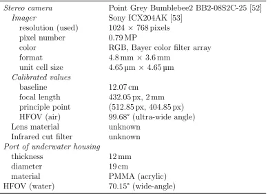
In this thesis, we will use a high resolution, colour, wide-angle flat port underwater short baseline stereo camera (see Fig. 2.7 and Table 2.1) in combination with SLAM. This system has several advantages, but also faces some challenges, which are solved in this thesis.
2.4. Proposed system design
Figure 2.7.: The high resolution, colour, wide-angle (in water) flat port underwater short baseline stereo camera used in this research
Table 2.1.: Underwater camera specification
Stereo camera Point Grey Bumblebee2 BB2-08S2C-25 [52]
Imager Sony ICX204AK [53]
resolution (used) 1024 × 768 pixels
pixel number 0.79 MP
color RGB, Bayer color filter array
format 4.8 mm ×3.6 mm
unit cell size 4.65µm ×4.65µm
Calibrated values
baseline 12.07 cm
focal length 432.05 px, 2 mm
principle point (512.85 px, 404.85 px) HFOV (air) 99.68° (ultra-wide angle)
Lens material unknown
Infrared cut filter unknown
Port of underwater housing
thickness 12 mm
diameter 19 cm
material PMMA (acrylic)
[image:41.595.76.482.407.690.2]more appropriate for the detection of small marine organisms. The colour information also helps to enable detecting biofouling. The higher frame rate of visual cameras also enables the real-time pose estimation required for the autonomous navigation of AUVs. In contrast to the VAN framework of the HAUV (section 2.2.2.2), the pose estimation can completely take place with only a single stereo camera, and does not require expen-sive navigation sensors, such as an RLG, a DVL or a DIDSON. In contrast to the narrow field of view of 45°in water of the monocular camera in the HAUV project, we use ultra wide-angle lenses with an ultra wide horizontal field of view of about 100° in air or a wide horizontal field of view of 70°in water, respectively. For a more detailed description of the terms wide-angle and ultra wide-angle see section 2.4.2. The wide-angle under-water camera allows a closer proximity to the hull, which is necessary in turbid under-water. Simultaneously, the vehicle can keep a relative high speed. For stable ship hull tracking, a narrow field of view would require a lower speed of the vehicle and a need to enforce smaller rotational velocities. A wide-angle underwater stereo camera is also beneficial for more accurate pose estimation and mapping, as a point on the hull is sensed from many more viewing angles. In comparison to the acoustic positioning system of Ridao et al. [50], our mapping and pose estimation system is completely independent from any external infrastructure. Additionally, as shown by Ridao et al. [50] and Hogue et al. [51], cameras enable the high resolution 3D mapping of underwater structures. In contrast to the 2D stereo vision-based ship hull reconstruction of Negahdaripour and Firoozfam [24], we focus in the thesis on the 3D reconstruction of the ship hull. Moreover, our mapping and localisation will be based on SLAM to bound the drift and to increase the accuracy in 3D reconstruction. In contrast to all prior SLAM-based underwater map-ping research, this thesis will incorporate the more accurate physics-based underwater camera model, which significantly increases the reconstruction accuracy in 2D imaging, 3D reconstruction and 3D pose estimation.
2.4.2. Discussion of the terms wide-angle and ultra wide-angle
2.4. Proposed system design
There is no clear definition of wide-angle and ultra wide-angle lenses. Wide-angle lenses often have focal lengths of 24 mm-35 mm, whereas ultra-wide angle lenses with (fixed) focal lengths of 14 mm-20 mm are currently sold [54, 55]. These focal lengths correspond to a HFOV of 54°-74°for wide-angle cameras or 84°-104°for ultra wide-angle cameras, respectively. Here, the HFOV in ° was calculated by the following commonly known formula:
HFOV = arctan
w 2f
360°
π , (2.2)
where w denotes the width of the image sensor andf the focal length.
3. Front port systems and wet-lenses
3.1. Introduction
Different optical systems for underwater imaging exist. The solutions include front port systems in connection with underwater housings, which embed usual in-air cameras, or alternatively, waterproof cameras with wet-lenses, which are specially designed for the use in water [56]. In the following sections, we give an overview of different optical systems for in-water imaging. We introduce the flat port, the dome port, the Ivanoff corrector and a well known wet lens product series and discuss their characteristics.
3.2. Flat port
Flat ports of underwater housings are front port systems with advantages and disad-vantages. Disadvantages consist in a narrowed field of view, chromatic aberration and pincushion distortion. As chromatic aberration and pincushion distortion are especially visible at larger angles, the use of flat ports is generally only recommended for lenses with a narrow field of view, such as macro or telephoto lenses [57].
can be beneficially deployed to partially compensate for the undesirable barrel distortion of ultra wide-angle lenses. As we will show in this chapter, the simple geometry of flat ports allows a straight forward calibration of the port’s pose (chapter 7), the correction of unwanted effects in 2D imaging (chapter 10) and accurate 3D reconstruction (chapter 8).
3.3. Dome port
The dome port is a front port system, whose centre of curvature ideally coincides with the camera’s centre of projection. Dome ports preserve the field of view underwater, reduce chromatic aberration and image distortion and can withstand high pressure [58]. If optimally aligned, dome port systems can be well approximated by the comparatively simple and well-known standard perspective camera model, and thus, standard tech-niques used for camera’s in air [59] can be exploited. Using the standard lens distortion model [60], sufficient correction of image distortion is possible with imperfect camera-to-dome port alignment, but also under optimal calibration conditions, the remaining distortion still depends on object distance [59].
Further disadvantage of dome ports are the strong reduction of the apparent object distance, the strong curvature of field [58, 61], slightly darker images due to a smaller f-number [58] and cost intensive manufacturing and alignment [58].
An undesirable effect for close-range vision is that objects, which are actually located at infinity, are perceived by the camera at a close distance, which corresponds to only about three times the radius of the dome [61]. Hence, the closest object distance is limited by the shortest available focal length of the camera. Close-up lenses are used to reduce this limitation but are subject to degradation in image quality.
The curvature of field of a dome port is another limiting factor. The lens of a camera designed for the use in air, cannot sharply focus the curved virtual image on the camera’s flat image plane. The loss in sharpness at larger radial distances is particularly visible at larger apertures with a reduced depth of field. This means a significant limitation for high resolution wide angle stereo.
3.4. Ivanoff Corrector
3.4. Ivanoff Corrector
The Ivanoff Corrector is a more sophisticated front port system consisting of a plano-convex lens being in contact with water and a bi-plano-convex lens placed in front of the camera [62, 63]. The virtual image created by the Ivanoff Corrector coincides with the object so that the magnification and the field of view are preserved and images stay distortion free.
The Ivanoff Corrector is not free of disadvantages, either. For a better correction of chromatic aberration, the corrector needs to be extended by further lens elements resulting in increased costs. In comparison to flat ports, the costs for manufacturing and alignment are higher, too. Another cost factor is that the Ivanoff corrector is lens specific, and thus, cannot be used with arbitrary cameras lenses. The optical geometry also depends on the index of refraction of water and changes, for instance, if the corrector is used in fresh or salt water. The limited field of view represents another disadvantage. Since the camera has a certain distance to the plano-convex lens, the diameter of the plano-convex lens grows relatively quickly with greater field of views, and is therefore not useful for wide angle stereo. Wakimoto [58] also criticised that the corrector was only designed on the basis of Gaussian optics, which describe the optical system only for small angles.
3.5. Wet lenses
4. Effects of refraction
4.1. Introduction
The use of a flat port in an underwater camera has numerous effects on 2D imaging. Some of these effects were mentioned in prior literature, but have not been summarised, yet. In this chapter, these refractive effects are summarised and background literature is clarified. Moreover, a fundamental magnification function is proposed, which enables the description of many effects in flat refractive geometry in a short form. This fundamental magnification function was also used to discover numerous new effects, which will be presented in this chapter. In addition to that, it will be shown that chromatic aberration and the thickness of the port of the underwater camera should not be neglected in wide-angle flat port underwater camera vision.
4.2. Related literature
The effects of refraction on image perception with one or two flat refractive interfaces have not been fully described yet. Recent literature is still addressing the problem of how certain parameters affect the image perceived behind a thin flat interface or a thicker window of a pool, aquarium or underwater housing.
0 150 300 450 600 750 900 0
100 200 300 400 500 600 700
v coordinate
[px]
u coordinate [px]
Figure 4.1.: Magnification effect and pincushion distortion by the refraction of light at a flat port (black crosses) in comparison to a perspective projection (grey crosses) of a point grid
by Ivanoff et al. and often enumerated in various literature are based on Gaussian optics and thus are only approximations for small angles and large object distances. Numerous effects at larger angles cannot be described. We propose a function that can exactly calculate refractive image magnification.
In his work on the design of underwater camera lenses from 1967, Wakimoto [58] described that flat ports produce a curved virtual image, so that flat surfaces cannot be exactly focused and appear blurry in the camera image at large radial distances. In comparison to the curvature of field of dome ports, the curvature of field of flat ports is small, however, as can be seen in [61]. Moreover, Wakimoto explains the occurrence of pincushion distortion, where the magnification increases with increasing angles. Pin-cushion distortion was illustrated in [66] and is depicted in Fig. 4.1. In addition to that, the effect of chromatic aberration was described, which is visible as red coloured fringes in the inside and blue coloured fringes on the outside of sharp edges. Wakimoto also mentions that at large object distances, the port thickness can be neglected. In this section, we demonstrate that the port thickness needs to be taken into account for close object distances, though.
In 2000, Kwon and Lindley [67] demonstrate that pincushion distortion cannot be modelled as a linear function of the image-plane coordinates alone, but also depends on the position of the object point in 3D space.
4.2. Related literature
that the radial pixel shift (radial distortion) increases with decreasing interface distance and, thus, especially occurs in underwater housings. The theoretical case of a single view point (SVP) model was studied, in which the interface is exactly located on the camera’s centre of projection so that all virtual focal points coincide. For the SVP case, a novel accurate radial distortion correction function was presented, which is object distance independent. Treibitz et al. have not mentioned, however, that the SVP model exists only for small angles, as we will show. For larger angles, which are determined by the total internal refraction within the port, multiple virtual focal points occur. Therefore, the still correct physics-based radial distortion correction function should not be directly related to the SVP model. Moreover, we show that the port thickness cannot be neglected any longer in the case of high-resolution, wide-angle underwater cameras and close object distances.
In the same year, Kunz and Singh [59] demonstrated the inadequacy of the often used standard perspective camera model and the standard lens distortion model to correct the image distortion of a thick port. It was also observed that the rotation of the port has a stronger effect on distortion than its displacement and cannot be appropriately approximated by the decentering/tangential distortion terms of the standard lens dis-tortion model. A visualisation of how an object is distorted by a tilted port was not given, though, and is completed by us in section 4.3.
In 2009, Chari and Sturm [69] established analogies between perspective projection and single interface refractive projection. Based on the derived refractive projection matrix, it was shown that a line in object space is projected to a quartic curve in image space. In terms of epipolar geometry, the refractive fundamental matrix was deduced, which relates the image points of an object point from two different camera views by the epipolar quartic curve. The main focus of Chari and Sturm is on theory and does contain actual visualisations of the epipolar quartic curve.
Gedge et al. [70] computed epipolar quartic curves (refractive epipolar curve) by piece-wise linear approximation, visualised and compared them with perspective epipolar lines and investigated the pixel distance between the curves. Unfortunately, only small image sections of the refractive epipolar curves were shown, but not their location over the whole image, which makes an understanding of the characteristics of the epipolar curves difficult. To clarify characteristics of epipolar curves over the whole image, a supplement figure is presented by us in section 4.3.
interface [68]. In both cases, the system converges against a SVP model for which the distortion can be modelled independently from the object distance. Moreover, Treibitz et al. extended their physics-based radial distortion correction function [68] for arbi-trary angles and port distances by incorporating the object distance as an additional parameter. Using this correction function, an accurate method was demonstrated to reduce the distortion of objects at known distances. Our work is strongly related to this work of Treibitz et al.. Their radial distortion correction function is focused on a single interface system, whereas we extend it for thick port systems. Additionally, we deduce the fundamental magnification function, which is closely related to the radial distortion correction function of Treibitz et al. and highlight its importance for the understanding of numerous effects of flat refractive geometry.
The work of Yau et al. [72] is one of the few recent publications that account for the effects of wavelength dependent refraction (dispersion). The effect that different coloured light is perceived at different image coordinates was exploited for triangulation-based calibration.
4.3. Proposed visualisation and clarifications of
background literature
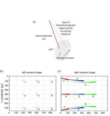
Supplementary to existing literature, we would like to briefly present the visualisations of the refractive epipolar curve over the whole image [69, 70], the image distortion caused by a non-parallel port [59] and the limitation of the validity of the SVP model [68, 71]. All findings result from the physics-based refractive camera model.
4.3. Proposed visualisation and clarifications of background literature
left/right camera port
(a)
back-projected ray
rays of forward-projected
object points at varying
distance
0 150 300 450 600 750 900 0 150 300 450 600 750 900 0
100 200 300 400 500 600 700
u coordinate [px] left camera image
(b) (c)
1 2 3
4 5 6
7 8 9
right camera image
v coordinate
[px]
u coordinate [px]
1 2
3
4 5 6
7
[image:53.595.95.452.105.481.2]8 9
point grid
tilted port camera air
water
0 150 300 450 600 750 900
0
100
200
300
400
500
600
700
u coordinate [px]
v coordinate
[px]
Figure 4.3.: Image of a point grid through a strongly tilted, large port (black crosses) in comparison to a perspective undistorted perception (grey crosses): The non-parallel port results in significant non-point symmetric image distortion (50°port pitch, 0.5 m point grid distance)
for a curve. In the upper and lower left section of the image (curves 1 and 7), the curves converge against a straight, outwards directed line. As the horizontal coordinates of the left image points decrease, the origins of their refractive epipolar curves (1, 2, 3, 7, 8 and 9) move towards the upper or lower image boundary. The visualisations show that refractive epipolar curves significantly differ from their perspective counterparts.
The camera image distortion caused by the refraction at a strongly tilted port is visualised in Fig. 4.3 using a front parallel flat grid of points. The image distortion shown significantly differs from the pincushion distortion of a parallel port depicted in Fig. 4.1. The distortion is neither point-symmetric nor correctable by standard decentering or tangential distortion models, respectively [59].
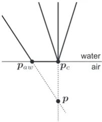
In Treibitz et al. [68, 71] the theoretical single viewpoint (SVP) model was described in which all rays meet in one common point, namely the camera’s centre of projection
4.4. Proposed refractive magnification function for the analysis of refraction
p pc
water air
[image:55.595.221.323.68.190.2]paw
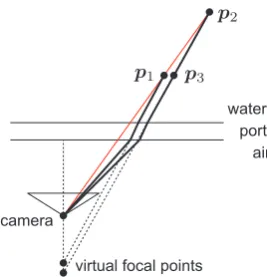
Figure 4.4.: Restriction of the validity of the SVP model: The image shows that the single viewpoint model is only applicable to small angles so that according rays meet in the common point pc. Larger angles result in a shift of the refrax paw with a different virtual focal point p.
4.4. Proposed refractive magnification function for the
analysis of refraction
In this section, we present a novel fundamental mathematical function that completely characterises the refractive magnification in the image of a camera with two refractive interfaces being parallel to the camera’s image plane. The equation also incorporates the single interface case and can be easily extended for arbitrary multi interface systems. In contrast to previous literature in which the magnification effects by arbitrary thick ports were only partially described, this proposed function allows the comprehensive understanding of refractive magnification, its dependency to all parameters in the system and its exact calculation. The function also allows a simplified qualitative evaluation of refractive effects, and is an alternative to an exact quantitative calculation requiring a more complicated refractive forward projection, which is not available in a closed form. The proposed function corresponds to an extension for arbitrary thick ports of the radial distortion correction function for single interfaces presented in [68, 71]. In con-trast to a representation of the relation between the undistorted and distorted radial coordinates in the form of a radial distortion function, we prefer the representation of the occurring magnification.
4.4.1. Newly discovered properties and methods
In addition to known properties, the function also served the authors as a basis to present newly discovered properties and to obtain more accurate calculations of the optical system, such as:
1. Closed-form calculation of the magnifications occurring in the image perceived through a thick, flat and parallel port. The extension for multiple thick layers is straight forward.
2. Increase/decrease in magnification with increasing object distance depending on the port thickness and the port distance
3. The magnification of close objects at the image centre does not only depend on the refractive indices of air and water, but also on the object’s distance and the port’s distance, thickness and index of refraction.
4. Calculation of an optimal port distance for reduced object distance dependency 5. Increased object distance dependency with increasing distance to the characteristic
radial distance
6. Closer objects are less distorted than more distant objects. 7. The magnification increases with growing port thickness.
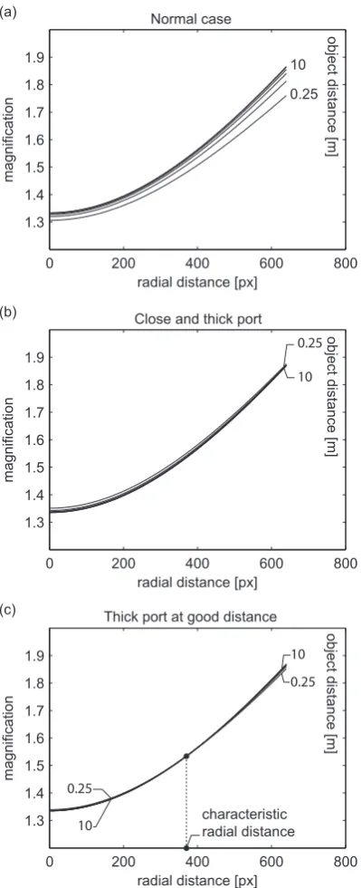
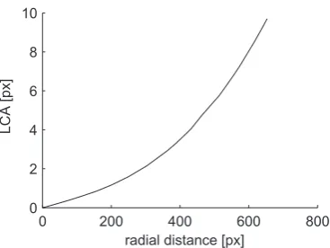
8. Chromatic aberration is object distance dependent at small object distances and loses its distance dependency at large object distances.
The derivation of these properties and methods is described in more detail in section 4.5.
4.4.2. Proposed extensions of the radial distortion correction
function for arbitrary thick ports
Treibitz et al. [68, 71] described the distance dependent radial distortion correction function for thin ports. Using our refractive magnification function, we extended their function for arbitrary thick ports and obtained the following results:
1. Precise radial distortion correction function for arbitrary thick ports, which are parallel to the image plane (see (4.7))
4.4. Proposed refractive magnification function for the analysis of refraction
4.4.3. Existing properties and methods
To date, different effects and properties of flat refractive geometry have been described. The following list summarises the effects and properties, which can be derived from our proposed fundamental refractive magnification function. The detailed derivations are omitted here.
1. In Gaussian optics, objects appear larger as if they were taken with a larger focal length, which is about nw/na times larger than the actual focal length [63]. 2. Distortion/magnification increases with radial distance (pincushion distortion) [58] 3. Increase in magnification with increasing object distance or decreasing port
dis-tance [68, 71]
4. Port distance independence if water is replaced by air [73]. The calibration of the port distance is not possible in air.
5. Object distance independent magnification with a thin port located on the camera’s centre of projection [68, 71]
6. The magnification of objects at large distances is independent of the port’s thick-ness [58], distance [68, 71] and index of refraction.
7. The change in the magnitude of magnification with respect to the port thickness is relatively small compared to the change caused by the radial distance [68, 71] 8. The magnification increases if the index of refraction of water or the index of
refraction of the port increase. It decreases with increasing index of refraction of air.
9. As a result of the wavelength specific image magnification (chromatic aberration), red coloured fringes appear relative to the image centre on the inside and blue coloured fringes on the outside of edges in the image [63, 58].
4.4.4. Derivation of the refractive magnification function
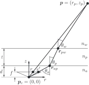
In this section, the proposed refractive magnification function is derived. The magni-fication function describes the ratio between the radial distances r0 and r of the image points of an object point at the distance zp perceived by a perspective camera with and without a parallel port (see Fig. 4.5)
θp
d f
t
θw
θa
r r z
r na
np nw
p= (rp, zp)
rpw
rap
[image:58.595.231.408.72.241.2]pc = (0,0)
Figure 4.5.: Illustration to calculate the refractive magnification function
fm is composed of a refractive back projection of the image pointr0 on an object plane, which is parallel to the camera’s image plane and located at the object distance zp, and a subsequent perspective forward projection. As the complicated refractive forward projection is not required, fm can be solved in a less complex, closed form.
The refractive back-projection is calculated as follows. It starts with a perspective back projection of the image point r0 onto the air-port interface. For the refrax on the air-port interface, we have
rap = r0d
f , (4.2)
where f denotes the focal length of the camera and d the port distance (see Fig. 4.5). Secondly, the relation between the object pointp= (rp, zp) and the refrax rap is defined by
rp =rap+ttanθp+ (zp−t−d) tanθw, (4.3) witht denoting the thickness of the port, andθp andθw representing the refracted angle in the port and the incident angle in water. Both angles are obtained from the refracted angle θa in air using Snells law
![Figure 1.3.: The possible results of a proposed, future ship hull inspection system for the3D reconstruction of the whole ship hull and the identification of the degreeand level of fouling (images from [4])](https://thumb-us.123doks.com/thumbv2/123dok_us/9036647.400021/21.595.63.487.99.300/figure-possible-proposed-inspection-reconstruction-identication-degreeand-fouling.webp)
![Figure 2.3.: VAN applied to the USS Saratoga aircraft carrier [49]: (a) Estimated 3Dtrajectory, (b) Textured map reconstruction, (c) Zoomed view](https://thumb-us.123doks.com/thumbv2/123dok_us/9036647.400021/37.595.49.496.196.529/figure-applied-saratoga-aircraft-estimated-dtrajectory-textured-reconstruction.webp)