ISSN Online: 1947-3818 ISSN Print: 1949-243X
DOI: 10.4236/epe.2019.119022 Sep. 25, 2019 342 Energy and Power Engineering
Augmentation of Heat Transfer in Pipe Flow
Using Plain Twisted Tape Inserts for Different
Twist Ratios
Maimonul Karim Chowdhury
1, Md. Moniruzzaman Bhuyan
2, Ujjwal Kumar Deb
2*1Department of Science & Humanities, Military Institute of Science and Technology, Mirpur Cantonment, Dhaka, Bangladesh 2Department of Mathematics, Chittagong University of Engineering & Technology, Chittagong, Bangladesh
Abstract
The heat transfer augmentation of plain twisted tape inserts for different twist ratios has been studied in this study. The data are conducted using the plain twisted tape insert with five different twist ratios respectively. The range of Reynolds number is considered under a uniform heat flux condition. In the case of simulation, the tapes are made from a stainless steel strip with a thickness of 2 mm. A tubular pipe with 850 mm U-loop length and twist length of 800 mm each is considered in our study for simulation. Water is used as working fluids inside the tube for our simulation. The simulation re-sults demonstrate that the important heat transfer parameters including Nusselt number (Nu), friction factor (f) and thermal performance index (η) are gradually increased with the increment of the twist ratio and reached at the saturated level while twist ratio is 3.5, afterward the thermal properties are decreased.
Keywords
Heat Transfer, Twist Ratio, Reynolds Number, Turbulent Flow, Simulation
1. Introduction
Nowadays in the industrial arena, the demands for mechanical devices are in-creasing gradually. For this purpose, the heat enhancement technology related to heat exchanger has drawn more attention to the development of such devices. From several studies, it is found that the augmentation of heat varies with dif-ferent heat transfer parameter including fluid flow rate, the dimension of pipe, different types of inserts, etc. Automobiles, Solar water heaters, Petrochemical How to cite this paper: Chowdhury, M.K.,
Bhuyan, Md.M. and Deb, U.K. (2019) Augmentation of Heat Transfer in Pipe Flow Using Plain Twisted Tape Inserts for Different Twist Ratios. Energy and Power Engineering, 11, 342-354.
https://doi.org/10.4236/epe.2019.119022
Received: August 6, 2019 Accepted: September 22, 2019 Published: September 25, 2019
Copyright © 2019 by author(s) and Scientific Research Publishing Inc. This work is licensed under the Creative Commons Attribution International License (CC BY 4.0).
http://creativecommons.org/licenses/by/4.0/
DOI: 10.4236/epe.2019.119022 343 Energy and Power Engineering Industries, Power plan, shell, and tube heat exchangers, etc. are the main appli-cation of the heat exchanger [1] [2]. Significant research work has been done on heat transfer enhancement technology to improve the system. The Heat Transfer techniques similarly promote secondary flow and twisted tape inserts due to their benefit of fixed performance and effectiveness in case of heat enhancement. By utilizing the twisted tape inserts, the flow becomes occlude and subsequently produce eddying due to increasing recirculation area between the closest wall surface and the twisted tape insert. So heat transfer in a tube can be increased by fluid mixing with the help of using inserts [3].
It is seen from recent studies that there are some experimental and theoretical methods have been considered on the enhancement of heat transfer coefficient and friction factor for formal fluid flows inside a tube fitted with different types of inserts to influence a swirl in the fluid flow [4] [5] [6] [7]. The study of Zo-zulya and Seigel [8] [9] observed that for twisted tape insert in a composite flow structure enhances the rate of heat transfer 2.0 to 3.0 times in comparison to a typical plain pipe.
On the other hand, Noothong et al. [2006] and Murugesan et al. [2009] stu-died experimentally the effect of different types of twisted-tape with twist ratios of 4.0 and 6.0. They found that enhancement of heat transfer and the Nusselt number increases with decreasing the twisted ratio, while friction factor also in-creases with decreasing the twisted ratio [10] [11]. In the year 2010, Eiamsa et al. investigated the heat transfer rate, friction factor and thermal enhancement fac-tor of the combined devices of twisted tape and wire coil. It is observed that the heat transfer and friction factor is more efficient in twisted tape than wire coil [12]. In the same year Raju et al. explained the influences of various width twisted tape in the range of 10 - 26 mm with the range of Reynolds number 6,000 - 13,500, in a circular tube of 27.5 mm inner diameter. They also compared the enhancement of heat transfer for a smooth tube with the twisted tape inserts and found that the rate increased from 36% to 48% [13]. In the same year, Mu-rugesan et al. performed an experiment on heat transfer, friction factor and thermal performance factor characteristics using v-cut twisted tape in a circular tube with twist ratios 2.0, 4.4, and 6.0. Three various combinations of width and depth ratio and also considered in their study. The results have shown that the average Nusselt number and friction factor in the tube with v-cut twisted tape increase with decreasing twisted ratios, width ratios and with increasing depth ratios [14].
DOI: 10.4236/epe.2019.119022 344 Energy and Power Engineering al., conducted an experimental study to enhance the efficiency of heat transfer for turbulent flow in a circular tube in case of rectangular-cut twisted tape in-serts with a constant twist ratio of 5.25. They found that the efficiency of heat transfer is increased by 1.9 to 2.3 times as compared with a plain tube [16].
In 2015, Sivakumar et al. considered a laminar flow study in a circular tube fitted with twisted tape inserts under a uniform wall heat flux boundary condi-tion. They found that the enhancement of heat transfer in a tube with twisted tape inserts was enhanced by 25% to 30% compared to that of the plain tube [17]. In the same year, Zhu and Chen et al. mentioned the effect of three kinds of twisted tape like single, multiple and triple. They concluded that the triple twisted tape enhanced the capability of heat transfer from 1.8 to 4.5 times more than the single and double. Besides this, they also have shown that the resistance of fluid flowing inside a pipe is varied from 6.0 to 21.2 times according to the shape of the twisted tape inserts [18]. Most recently Bhattacharya et al. simulate both experimentally and numerically the characteristics of heat transfer in a round tube built-in with twisted tape with the flowing parameters, Reynolds number range 100 - 2000, the twisted ratio and the angle at the entrance of the tube. It was observed that the rate of heat transfer enhanced by increasing the entrance angle and decreasing the twisted ratio. Moreover, the efficiency of heat transfer enhancement decreases with increasing the Reynolds numbers [19].
From the above literature, we found various experimental and numerical me-thods to enhance the quality of heat transfer technique through a pipe fitted with several types of inserts. In this paper, our goal to present the heat transfers phe-nomena in a circular pipe using the Finite Element Method (FEM). The FEM based software COMSOL MULTIPHYSICS is used for our numerical simula-tion. Most of the heat-generating the engine uses a straight portion of the circu-lar tube to emit heat from the engine. Till now no studies have been considered for U-loop pipe to study heat transfer. However, the scenario is different in most practical cases. This study deals with a non-isothermal turbulent flow model for simulation. Emphasis is given on the improvements of the twisted geometry for the rate of heat transfer, friction factor, and thermal performance. The effects of the geometrical shape of twisted tape inserts with different tape ratios 2.9, 3.0, 3.25, 3.5 and 4.0 on the friction factor, Nusselt’s number (Nu) and thermal en-hancement factor (η) are considered. The numerical studies are carried out in turbulent flow for Reynolds numbers in the range of 5,000 - 25,000 under a uni-form heat flux environment.
2. Mathematical Model
phenome-DOI: 10.4236/epe.2019.119022 345 Energy and Power Engineering na through a pipe for a non-isothermal Turbulent flow and the governing equa-tions which describe the flows are the Continuity Equation and the Navier- Stokes equations are given below [20].
( )
u 0t
ρ ρ
∂
+ ∇ ⋅ =
∂
(1)
(
)
(
)
(
( )
T)
2(
)(
)
2]
3 3
T T
u u
pI u u u I KI F
ρ
µ µ µ µ ρ
⋅∇
= ∇ ⋅ − + + ∇ + ∇ − + ∇ ⋅ − +
(2)
As the domain is a Tubular U-loop pipe, to get a better prediction about the flow around the curve region, we consider the k-ω turbulent model. The para-meters k and ω are given by the following equations.
(
)
(
*)
*T k k k
u k p k
ρ
⋅∇ = ∇ ⋅µ µ σ
+ ∇ + −ρβ ω
(3)(
)
(
)
2T k
u p
k
ω ω
ρ ⋅∇ ω= ∇ ⋅ µ µ σ+ ∇ω+α −ρβω
(4)
T k
µ ρ
ω
= (5)
( )
(
T)
2(
)
2 2[ :
3 3
k T
p =µ ∇u ∇ + ∇u u − ∇ ⋅u − ρk u∇ ⋅
(6)
The heat transfer rate through a fluid is governed by the following equation:
(
)
(
)
:(
)
p
p
T T
C u T q S u p Q
t t t
ρ ρ ρ τ ρ ∂ ∂ ∂ + ⋅∇ = − ∇ ⋅ + − + ⋅∇ + ∂ ∂ ∂
(7)
where,
( )
(
)
1 2
S= ∇ + ∇u u T
(8)
Here in Equation (7), Q contains heat source other than viscous heating (SI unit: W/m3). For obtaining the heat transfer term used Fourier law of heat con-duction, the convective heat flux, q is proportional to the temperature gradient.
i i T q K x ∂ = −
∂ (9)
where K is the thermal conductivity. The convective heat flux is given by
i ij j i T q K x ∂ = − ∂
∑
The term τ:S in Equation (7) represents viscous heating of a fluid can be written in the following form:
: mn mn
m n
S S
τ =
∑∑
τThe term
(
)
p
T u p
T t
ρ ρ
ρ
∂ ∂ + ⋅∇
∂ ∂ represents a pressure work is responsible
DOI: 10.4236/epe.2019.119022 346 Energy and Power Engineering By using the Equations (7) and (8) we find
(
)
(
)
p T p
C C u T k T Q
t
ρ ∂ +ρ ⋅∇ = ∇ ⋅ ∇ + ∂
(10)
If the velocity is to zero the equation becomes
(
)
p T
C k T Q
t
ρ ∂ + ∇ ⋅ − ∇ =
∂ (11)
Again we obtain convective heat transfer coefficient
w b
Q h
T T
=
− (12)
where Tw and Tb are the wall and bulk temperature respectively and Tb Tout2Tin +
= ,
The Nusselt number is calculated by
hD Nu
k
= (13)
Here D is the diameter of the tube. Depended on the numerically measured pressure drop, the Darcy friction factor can be computed as following [21] [22]:
p h gρ
∆ =
(14)
where ∆p is pressure drop and head loss is h, 2
2
flu h
gD
= (15)
From Equation (14) and (15) we have
2 2 l fu p D ρ
∆ = ⋅
(16)
where, Δp is the pressure drop across the length of the tube l. The performance Evaluation Criterion (PEC) is defined as follows [23]:
0 1 6 0 Nu Nu f f η= (17)
where Nu0 and f0are the Nusselt number and the friction factor of the plain tube respectively.
Boundary Conditions
In this flow model, the boundary conditions are assumed a different velocity for Reynolds number at the inlet and temperature of the fluid is T T= in=293.15 K. The no-slip condition i.e.u = 0, where utangis the tangential velocity, at the inner wall of the tube and the wall function at the outlet of the domain governed by the following equations.
0
DOI: 10.4236/epe.2019.119022 347 Energy and Power Engineering
(
)
(
( )
T)
2(
)(
)
23 3
T T tang
w
u
u u u I kI n τ u
µ µ µ µ ρ ρ
δ
+ ∇ + ∇ − + ∇ ⋅ − = −
(19)
(
)
tang
u = − ⋅u u n n
(20) 2
0,
v w
c K k n
K
µ
ω ρ
δ µ
∇ ⋅ = = − (21)
3. Computational Domain and Mesh Design
Design of computational domain with a twist ratio 3.5, and a twisted tape are shown in Figures 1(a)-(c). In our simulation, we have considered a typical U-loop circular tube whose length is 1875.08 mm, inner diameter 26.6 mm, out-er diametout-er 33 mm. The dimension of the insout-ert is thickness 2 mm, breadth 26 mm and length 120 mm in each strip. To reach a satisfactory computational ex-actness we continually change the mesh design until the outcomes obtained. As our domain length is large thus computer processor capacity becomes a signifi-cant issue for the computational study. The fine mesh is used along with the whole computational model for numerical simulation. We used 16 GB DDR3 RAM, Intel Core i7 processor-based computer for our simulation. The dimen-sion of the twisted tape, mesh design of the inlet and mesh domain of the pipe are shown in Figure 1(d) & Figure 1(e). A comparison of mesh design among different twist ratios [2.9, 3.0, 3.25, 3.5 and 4.0] insert combinations have shown in Table 1 and Table 2 respectively.
4. Numerical Results
The main aim of our numerical simulation is to ensure the enhancement of heat transfer phenomenon in a U-loop tubular pipe for a non-isothermal tur-bulent flow considered the twist ratio. The simulation is taken for independent of time. For this investigation, the thickness of the tube is neglected and the boundary conditions for the tube are being measured as a uniform heat flux adjoining the water domain layer. As we have only given attention to improv-ing the heat transfer rate by the flowimprov-ing fluid thus we ignored the flow of heat in the solid tube. We considered water as our working fluid. To realize the ef-fect of inserts into the heat transfer phenomenon, we carried out the simula-tions by various types of twisted ratio and the twist ratios are 2.9, 3.0 3.25, 3.50 and 4.0 respectively.
DOI: 10.4236/epe.2019.119022 348 Energy and Power Engineering
Figure 1. The computational domain (a) with insert, (b) measurement of twisted ratio, (c) full length twist domain, (d) cross-section of mesh design, (e) mesh design with inserts.
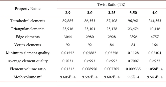
Table 1. Finer Mesh elements comparison of a tubular U-loop pipe with different twist ratios of inserts.
Property Name Twist Ratio (TR)
2.9 3.0 3.25 3.50 4.0
Tetrahedral elements 89,885 86,353 87,108 96,961 244,353
Triangular elements 23,946 23,404 23,478 23,474 40,446
Edge elements 3044 2980 2928 2896 4757
Vertex elements 92 92 84 84 164
Minimum element quality 0.04552 0.05882 0.05256 0.1128 0.02404
Average element quality 0.7031 0.6993 0.6992 0.7007 0.6937
Element volume ratio 0.01212 0.008956 0.007705 0.009335 1.058E−4
[image:7.595.210.539.566.738.2]DOI: 10.4236/epe.2019.119022 349 Energy and Power Engineering
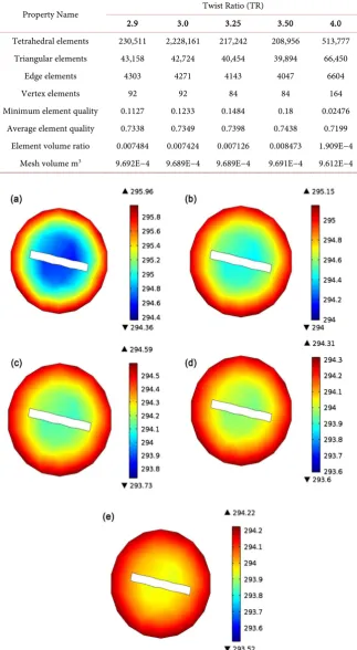
Table 2. Extra fine Mesh elements comparison of a tubular U-loop pipe with different twist ratios of inserts.
Property Name Twist Ratio (TR)
2.9 3.0 3.25 3.50 4.0
Tetrahedral elements 230,511 2,228,161 217,242 208,956 513,777
Triangular elements 43,158 42,724 40,454 39,894 66,450
Edge elements 4303 4271 4143 4047 6604
Vertex elements 92 92 84 84 164
Minimum element quality 0.1127 0.1233 0.1484 0.18 0.02476
Average element quality 0.7338 0.7349 0.7398 0.7438 0.7199
Element volume ratio 0.007484 0.007424 0.007126 0.008473 1.909E−4 Mesh volume m3 9.692E−4 9.689E−4 9.689E−4 9.691E−4 9.612E−4
DOI: 10.4236/epe.2019.119022 350 Energy and Power Engineering
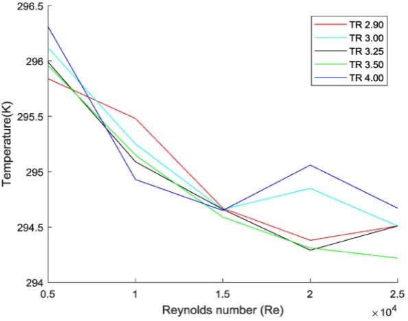
4.1. Temperature Performance Evaluation
Besides the twist ratio 3.5 we also have investigated for all ratios like 2.9, 3.0, 3.25, 3.5 and 4.0 to check the heat transfer phenomena in different twist ratio. We found different results are shown in Figure 3. This figure represents the temperature variation with the increment of Reynolds numbers for different twist ratios. For the twist ratio 3.5, we observe a gradual temperature fall with the increase of Reynolds numbers. We observed the same pattern for ratio 2.9 and 3.0 while 3.25 and 4.0. It is shown quite the opposite pattern though both are decreased. It seems 3.5 is the best twist ratio and the saturated level for the maximum heat transfer.
4.2. Nusselt Number Performance Evaluation
In terms of Nusselt Number (Nu) with Reynolds number (Re), the heat transfer variations are presented in Figure 4. Here we found that Nusselt number is in-creased with the Reynolds number for all the ratios. At a given Reynolds number with the twist ratio 3.5 yields higher Nusselt number than the other twist ratio. Figure 4 also shows the effect of twist ratios for heat transfer. We also observed that the Nusselts number increases with decreasing twist ratio. The twisted tape inserts with smaller twist ratio processes more twist numbers and shows better Nusselt numbers (Nu). This creates higher turbulent intensity and consequently gives better heat transfer. From the simulation result of range, the uses of the twist ratio 3.5 provide higher Nusselt number than the ratios 2.9, 3.0, 3.25 and 4.0 respectively [6] [8].
4.3. Friction Factor Performance Evaluation
[image:9.595.225.523.477.711.2]The variation of pressure drop in terms of friction factor (f) with Reynolds
DOI: 10.4236/epe.2019.119022 351 Energy and Power Engineering
Figure 4. Effect of Nusselt number along with Reynolds number for different twist ratios (TR 2.90, 3.0, 3.25, 3.5 and 4.0).
Figure 5. Combined graph of friction factor with Reynolds number.
[image:10.595.226.521.351.585.2]DOI: 10.4236/epe.2019.119022 352 Energy and Power Engineering by the weaken swirl intensity effect of friction with Reynolds number for differ-ent twist ratios, which follow the result of S. Eiamsa-ard of convective heat transfer in a circular tube with short-length twisted tape insert.
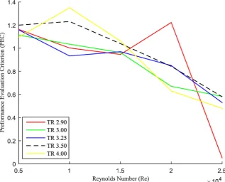
4.4. Thermal Performance Evaluation Criterion (PEC)
The performance evaluation criterion (PEC) in a tube fitted with different twisted tapes obtained using numerical simulations are shown in Figure 6. It is observed that the PEC value tends to increase with increasing Reynolds number for 5000 to 10,000 but it’s shown in different behavior for 15,000 to 25,000. The tubes fitted with twisted tapes inserts of the ratio gives better overall heat trans-fer performance than the tubes with twisted tapes of the other twist ratios [2.9, 3.0, 3.25 and 4.0].
5. Conclusion
[image:11.595.214.532.449.705.2]A computational study of the heat transfer phenomenon of fluid flow through a tubular pipe with five different twist ratios [2.9, 3.0, 3.25, 3.5 and 4.0] for a non-isothermal turbulent flow has been studied. The water consider as working fluid in our study and the initial temperature is assumed at the inlet is 293.15 K. A no-slip condition on the wall and wall function on the outlet is assumed. For our simulation, we assumed that better heat transfer rate is found while the twist ratio is 3.5 compared with other ratios while the Reynolds number gradually in-creased from 5000 to 25,000. We found the same scenario for the Nusselts num-ber as well. Also, we have observed that for pressure is reducing when the Rey-nolds (Re) numbers are increased.
DOI: 10.4236/epe.2019.119022 353 Energy and Power Engineering
Acknowledgements
The authors gratefully acknowledge the technical support provided by the Cen-tre of Excellence in Mathematics, Department of Mathematics, Mahidol Univer-sity, Bangkok 10400, Thailand and the simulation lab, Department of Mathe-matics, Chittagong University of Engineering & Technology, Chittagong, Ban-gladesh.
Conflicts of Interest
The authors declare no conflicts of interest regarding the publication of this pa-per.
References
[1] Bergles, A.E. and Webb, R.L. (1985) A Guide to the Literature on Convective Heat Transfer Augmentation. Advance Enhanced Heat Transfer, 43, 81-89.
[2] Agarwalt, S.K. and Rao, M.R. (1996) Heat Transfer Augmentation for the Flow of a Various Liquid in Circular Tubes Using Twisted Tape Inserts. International Heat and Mass Transfer, 39, 3547-3557. https://doi.org/10.1016/0017-9310(96)00039-7 [3] Manglik, R.M. and Bergles, A.E. (1991) Heat Transfer Enhancement of in Tube
Flows in Process Heat Exchangers by Means of Twisted-Tape Inserts. Heat Transfer Laboratory, Report No. HTL-8, Rensselaer Polytechnic Institute, Troy, New York. [4] Ray, S. and Date, A.W. (2003) Friction and Heat Transfer Characteristics of Flow
through Square Duct with Twisted Tape Insert. International Journal of Heat and Mass Transfer, 46, 889-902. https://doi.org/10.1016/S0017-9310(02)00355-1
[5] Bas, H. and Ozceyhan, V. (2012) Heat Transfer Enhancement in a Tube with Twisted Tape Inserts Placed Separately from the Tube Wall. Experimental Thermal and Fluid Science, 41, 51-58. https://doi.org/10.1016/j.expthermflusci.2012.03.008 [6] Akhavan-Behabadi, M. (2009) Effect of Twisted Tape Insert on Heat Transfer and
Pressure Drop in Horizontal Evaporators for the Flow of R-134a. International Journal of Refrigeration, 32, 922-930. https://doi.org/10.1016/j.ijrefrig.2008.11.004 [7] Eiamsa-ard, S., Thaingpong, C., Eiamsa-ard, P. and Promvinge, P. (2009)
Convec-tive Heat Transfer in a Circular Tube with Short-Length Twisted Tape Insert. In-ternational Communication in Heat and Mass Transfer, 36, 365-371.
https://doi.org/10.1016/j.icheatmasstransfer.2009.01.006
[8] Zozulya, N. and Shkuratov, I.Y. (1974) Effect of the Length of a Twisted-Tape Tur-bulence Promoter and of Its Initial Twisting Pitch of Augmenting of Heat Transfer Inside a Tube.Heat Transfer-Soviet Research, 6, 98-100.
[9] Wang, L. and Sunden, B. (2002) Performance Comparison of Some Tube Inserts. International Communications in Heat and Mass Transfer, 29, 45-56.
https://doi.org/10.1016/S0735-1933(01)00323-2
[10] Noothong, W., Eiamsa-Ard, S. and Promvonge, P. (2006) Effect of Twisted-Tape Inserts on Heat Transfer in a Tube. International Conference on Sustainable Energy and Environment, A-030(P).
[11] Murugesan, P. (2009) Heat Transfer and Pressure Drop Characteristics of Turbu-lent Flow in a Tube Fitted with Trapezoidal-Cut Twisted Tape Insert. International Journal of Academic Research, 1, 123-128.
DOI: 10.4236/epe.2019.119022 354 Energy and Power Engineering Tape Inserts on Thermal Performance Characteristics. International Communica-tions in Heat and Mass Transfer, 37, 850-856.
https://doi.org/10.1016/j.icheatmasstransfer.2010.05.012
[13] Sarada, S.N. (2010) Enhancement of Heat Transfer Using Varying Width Twisted Tape Inserts. International Journal of Engineering Science and Technology, 2, 107-118. https://doi.org/10.4314/ijest.v2i6.63702
[14] Murugesan, P., Malyilsamy, K., Suresh, S. and Srinivasan, P.S.S. (2011) Heat Trans-fer and Pressure Drop Characteristics in a Circular Tube Fitted with and without V-Cut Twisted Tape Insert. International Communications in Heat and Mass Transfer, 38, 329-334. https://doi.org/10.1016/j.icheatmasstransfer.2010.11.010 [15] Guo, J., Fan, A., Zhang, X. and Liu, W. (2011) A Numerical Study on Heat Transfer
and Friction Factor Characteristics of Laminar Flow in a Circular Tube Fitted with Center-Cleared Twisted Tape. International Journal of Thermal Sciences, 50, 1263-1270. https://doi.org/10.1016/j.ijthermalsci.2011.02.010
[16] Salam, B., Biswas, S., Saha, S. and Bhuiya, M.M.K. (2013) Heat Transfer Enhance-ment in a Tube Using Rectangular-Cut Twisted Tape Insert. Procedia Engineering, 56, 96-103. https://doi.org/10.1016/j.proeng.2013.03.094
[17] Sivakumar, K. (2015) Experimental Investigation of Twisted Tape Insert on Lami-nar Flow with Uniform Heat Flux for Enhancement of Heat Transfer. Journal of Chemical and Pharmaceutical Sciences, 974, 2115-2126.
[18] Zhu, J.D. and Chen, H. (2015) Numerical Study on Enhanced Heat Transfer by Twisted Tape Inserts inside Tubes. Procedia Engineering, 130, 256-262.
https://doi.org/10.1016/j.proeng.2015.12.219
[19] Bhattacharyya, S., Chattopadhyay, H. and Haldar, A. (2018) Design of Twisted Tape Turbulator at Different Entrance Angle for Heat Transfer Enhancement in a Solar Heater. Beni-Suef University Journal of Basic and Applied Sciences, 7, 118-126. https://doi.org/10.1016/j.bjbas.2017.08.003
[20] Cuvelier, C., Segal, A. and Van Steenhoven, A.A. (1986) Finite Element Methods and Navier-Stokes Equations. D. Reidel Publishing Company, Holland.
[21] White, F.M. (1998) Fluid Mechanics. 4th Edition, McGraw-Hill Company, New York.
[22] Piriyarungrod, N., Eiaamsaard, S., Thainpong, C., Pimsarn, M. and Nanan, K. (2015) Heat Transfer Enhancement by Tapered Twisted Tape Inserts. Chemical En-gineering and Processing, 96, 62-71. https://doi.org/10.1016/j.cep.2015.08.002 [23] Fan, J.F., Ding, W.K., Zhang, J.F., He, Y.L. and Tao, W.Q. (2009) A Performance