A Joint-Coding Scheme With Crosstalk Avoidance
Lei Zhou, Ning Wu, Fen,Ge
Abstract—The reliable transfer in Network on Chip can be guaranteed by crosstalk avoidance and error detection code. In this paper, we propose a joint coding scheme combined with crosstalk avoidance coding with error control coding. The Fi-bonacci numeral system is applied to satisfy the requirement of crosstalk avoidance coding, and the error detection is achieved by adding parity bits. We also implement the codec in register transfer level. Furthermore, the schemes of codec applying to fault-tolerant router are analyzed. The experimental result shows that ”once encode, multiple decode” scheme outperforms other schemes in trade-off of delay, area and power.
Index Terms—Network On Chip; Fault Tolerant; Crosstalk Avoidance; CODEC
I. INTRODUCTION
T
HE rapid scaling of technology into the deep sub-micron regime has been accompanied by a dramatic increase in transistor densities. According to ITRS’ predic-tion, up to 4 billion transistors will be integrated into one chip since 2010 [1]. However, the increasing densities also lead to increasing possibility of instantaneous fault because of more crosstalk noises and leakage current. To increase the reliability of system, the crosstalk avoidance and error detection scheme has become the critical issues in Network on Chip (NOC) design.In recent years, there has been an evolving effort in error detection and correction mechanisms in the communication subsystem, and crosstalk avoidance codes (CACs) are con-sidered as effective scheme to reduce the mutual inter-wire coupling capacitance and hence the energy dissipation of wire segments [2]. Yuet al. [3]. proposed an adaptive error control method for switch-to-switch links in a variable noise environment, to meet reliability requirements and achieve energy-efficiency. Srinivas et al. [4] proposed bus-encoding techniques that decrease crosstalk between wires and avoid adversarial switching patterns on the data bus. However, the data should be divided into groups according to the width. Ganguly et al. [5] proposed joint crosstalk avoidance and triple-error-correction / quadruple-error-detection codes, and their performance was evaluated in different NOC fabrics. Nevertheless this coding scheme can applied to any width of data, the code redundancy rate is larger than others.
In this paper, we propose a joint coding scheme which combines crosstalk avoidance coding with error control cod-ing. The main idea of this scheme is to represent datawords into Fibonacci numeral system and add parity bits into cod-ing, for providing the fault detecting capability and avoiding
Manuscript received July 18, 2011; revised August 6, 2011. This work was supported in part by the National Natural Science Foundation of China (No. 61076019), the Jiangsu Natural Science Foundation (No. BK2008387) and the China Postdoctoral Science Foundation (No. 20100481134).
L. Zhou is with College of Information Science and Technology,Nanjing University of Aerospace and Astronautics, Nanjing, 210016, China and Col-lege of Information Engineering, Yangzhou University, Yangzhou, 225002, China e-mail: [email protected]
[image:1.595.355.496.133.287.2]N. Wu and F. Ge are with Nanjing University of Aerospace and Astro-nautics.
Fig. 1: The Topology of 2D-mesh
crosstalk noise simultaneously. Furthermore, the RTL level implementation of CODECs is offered. The codec is applied to fault-tolerant router based on End-to-End protocol and Point-to-Point protocol, and the performance of these error controlling schemes is also analyzed.
II. ERRORCONTROLINNOCLINKS
The proposed coding scheme is based on the commonly used interconnect architecture Mesh, as shown in Fig. 1. Each router connects neighbors in four directions. Data exchange between the functional blocks takes place in the form of packets. This scheme divides packets into fixed-length flow control units (flits),as shown in Fig. 2, with buffers storing only a few flits. At most 8 flits compose a packet, including one header flit and 7 payloads. Header flit, which contained routing information, like source and destination address, packet length, etc, enables the switches to establish a path and subsequent flits simply follow this path in a pipelined fashion.
The purpose of the error control mechanism is to deliver the datawords over channel reliably. The mechanism can be classified into two ways: End-to-End protocol and Point-to-Point protocol. End-to-End protocol means the error control only executes once in the data transfer between functional blocks. In Point-to-Point protocol, the error control should be performed in every router the datawords pass through. In general, the hamming, parity code or CRC is applied to detect and the data retransmission is applied to correct the error. Note that the increasing possibility of instantaneous fault leads to the local congestion because of the increasing number of packet retransmission.
Fig. 2: Structure of Packet
Fig. 3: Construction of Joint Code
are defined as 3-bit patterns ”101” and ”010”. For example, 1100110 has no forbidden pattern for there is no three consecutive bits. It has been shown in [7] that a code which contains no forbidden pattern experiences maximum crosstalk of no greater than2·C.
III. THEJOINTCODING
Although CAC and ECC address delay and reliability indi-vidually, the combination of CAC and ECC should satisfy the following conditions [4]. Firstly, CAC needs to be performed in first step because it involves nonlinear and disruptive mapping from data to codeword; Secondly, ECC needs to be systematic to ensure that the reduction in transition activity and the peak coupling transition constraint are maintained. And lastly the additional parity bits generated by ECC should be encoded by a linear CAC to ensure they do not suffer from crosstalk delay. According to the constraints of above, the construction of joint code is shown as Fig. 3.
Nonlinear CAC is used prior to other encodings, k bits data is encoded tol bits codeword. After that the additional
mparity bits are added to the codeword to contain the error detection ability, then thembits are further encoded by linear CAC for crosstalk avoidance to obtainmc bits. Totall+mc
bits are sent over the bus lastly.
Mutyam [8] proposed a bus encoding technique using a variant of binary Fibonacci representation as CAC scheme, which indicates that any n bits vector can be expressed by Fibonacci elements:
v=
m−1
X
k=0
dk·fk dk∈ {0,1} (1)
wheredk is thek-th bit in vector whilef is the Fibonacci
element. Here we define the Fibonacci Sequences as follow:
fm=
0 (m= 0)
1 (m= 1)
fm−1+fm−2 (m≥2)
(2)
Fig. 4: Joint Code Algorithm
The literature [8] has proved that the data encoded by binary Fibonacci representation can prevent crosstalk delay; therefore we use binary Fibonacci representation as CAC. Due to the efficient multiple bits error detecting ability of CAC, the ECC only needs to detect one bit error by parity bits. So the encoding algorithm is expressed as Fig. 4.
As the whole codewords satisfy FPC, it has the crosstalk avoidance ability definitely referring to [7]. Here we only need to prove the one bit error detection ability of additional parity bits.
Theorem 1: The additional parity bits of codeword pos-sess one bit error detection ability.
Proof: ECC shields datawords by generating two ad-ditional parity bits, which refers to the principle of even or odd parity. When ECC gets codeworddm, dk+1, dkgenerated
by CAC, it created parity bit valuepthrough bitwise XOR operator. Then the parity bit value is extend to two parity bitsdm+1, dm+2 to satisfy FPC. According to FPC, the first
bitdm+1should equal to the last bit of codeword of CAC, so
the parity ability is guaranteed bydm+2. For example, if we
use even parity, the parity bits should equal to 00 or 11 when
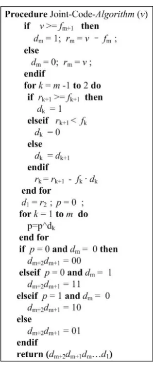
p= 0. Otherwise the parity bits is 01 or 10 when p = 1. The truth table of relationship betweenp, dmand parity bits
dm+1, dm+2is shown in Table I.From Table I we can deduce
that dm+1 =dm, dm+2=pLdm=pLdm+1 =d1Ld2
. . .L
[image:2.595.71.268.49.280.2]TABLE I: Truth table of parity bits
p dm dm+2 dm+1
0 0 0 0
0 1 1 1
1 0 1 0
1 1 0 1
Fig. 5: The implementation of encoder
parity bit of the whole codeword. The derived process is consistent when using odd parity principle.
IV. IMPLEMENTATION OFCODEC
According to the algorithm of joint code, encoder trans-forms the n-bit binary data into m-bit Fibonacci code, and adds two additional parity bits to the tail of it. n and m
satisfy2n< fm+2, therefore the original 32 bits binary data
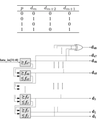
is mapped to 46 bits Fibonacci code. Adding 2 parity bits, the total width of codeword is 48. The encoder based on algorithm can be implemented using the structure illustrated in Fig. 5.
The original 32 bits data is transferred into encoder, compared withf47to determine the value ofd46 andd47. In
the next stage, the rest of the inputr46is compared withf45
andf46to generated45, and then the remaining is transferred
to next continuously until d1 is left. Lastly d47,. . .d2d1 is
performed by XOR gate to generated48. The combinational
logic depth of encoder is too large, so circuit is divided into 8 sections to generate the part of codes, then merges them. The process of each section consumes 1 cycle, the encoding process is completed in 9 cycles totally.
Fig. 6 depicts the structure of decoder. When received 48 bits codeword, decoder firstly uses bitwise XOR to d47,
. . .d2d1 for recreating the parity value p. If p6=d48, there
may occur data corruption during data transfer, the error flag
e will be marked and routers will request retransmission. Otherwise the circuit transforms the Fibonacci code into binary data according to formula (1) and transfer to the next router.
V. EXPERIMENTRESULTANDANALYSIS
A. The Experiment Scheme
To evaluate the complexity of the CODECs, we imple-mented the fault-tolerant router which applied to the joint code and constructed 4×4 2D-mesh network. Packet injec-tion follows a uniform distribuinjec-tion. According to default bit error rate (BER), we injected error bits in links between
Fig. 6: The implementation of decoder
routers to simulate the occurrence of instantaneous fault. We propose three types combination of CODEC and router:
1) Once encode, once decode: The combination follows End-to-End protocol, that dataword is only encoded in the router which connected to source function block and decoded by destination router.
2) Multiple encode, multiple decode: The combination follows Point-to-Point protocol, that dataword is en-coded and deen-coded by every router the dataword passed in the routing path.
3) Once encode, multiple decode: dataword is only en-coded in source router, the routers in routing path de-code and parity the de-codeword, and transfer the original codeword directly if codeword has no bit error. The experiment implements the three error-control schemes mentioned above using Verilog HDL, and then synthesizes them in Design Complier of Synopsys. Based on it, the performance of average delay, power and area is discussed as follows.
B. Delay
The delay of CODEC is fixed, therefore the extra delay suffered in three types can be calculated as follow:
∆Delay1 =Delayencoder+Delaydecoder (3)
∆Delay2 =α(Delayencoder+Delaydecoder) (4)
∆Delay3 =Delayencoder+αDelaydecoder (5)
WhereDelayencoderandDelaydecoderare the delay of the
encoder and decoder respectively, the value are 9 cycles and 1 cycle respectively according to the implementation in section III.αexpresses the average hops of 2D-mesh network, this implies that:
α= Pm
j=1
Pn
i=1hopij
2×C2 m×n
(6)
wherem andn indicate the number of nodes in horizon and vertical direction of the network, and hopij is hops
from node i to j. We use 4 ×4 2D-mesh network as the experimental network, m = 4, n = 4. In experiments the injection rates follow uniform distribution, therefore
[image:3.595.88.252.68.270.2]TABLE II: Power and Area of Codec
Power Area(µm2)
Dynamic(mW) Leakage(µW) Total(mW) Combinational Logic Sequential Logic Total
Decoder 1.9959 32.1384 2.0280 365897.35 73483.50 439380.85 Encoder 0.8106 1.7212 0.8124 29069.40 2767.56 31836.96
[image:4.595.181.562.149.491.2](a) (b) (c)
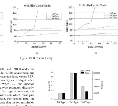
Fig. 7: BER versus Delay
6/10000, 7/10000, 8/10000, 9/10000 and 1/1000 under the injection rate of 0.04flit/cycle/node, 0.08flit/cycle/node and 0.10flit/cycle/node, Fig.7 plots the average delay versus BER. The gap between delays of three types is slight when BER and injection rates are low. When BER and injection rates increase, the delay of first type promotes distinctly. Although the delay of codecs in first type is smallest, this type involves more packet retransmission which must pass through each router in routing path. For second type, the increasing of delay is limited because that the retransmission happened when router finds error in the routing path, this method shortens the path of retransmission effectively. Note that in low BER and injection rates, the delay in this type is larger than others for this type suffers more delay penalty in encoding and decoding process. Therefore this type is not fitted to low load system. The third type avoids encoding during routing process compared to the second type, therefore the delay outperforms than others.
C. Power and Area
The codecs are synthesized using a SMIC 0.18-µmCMOS standard cell library in Design Compiler of Synopsys, The results of power and area are shown in Table II.
To simplify the comparison, we only evaluate the con-sumption of power and area caused by codecs. Fig.8 plots the consumption of power and area under three types.
In first type, encoding and decoding process in source router and destination router respectively, therefore codecs are placed in local port of each router. In second first type, encoding and decoding happened in every hop in routing, codecs should be placed in ports of four directions. In third type, encoding is processed when datawords enter the network and the routers decode in routing path, so one encoder is placed in local port and four decodes are placed in ports of four directions. It is obvious that the second type
Fig. 8: The comparison of power and area
consumes more power and area than others. Note that the consumption of the third type is larger than the first type, but the gap between them is slight because the consumption of decoder is far less than encoder.
VI. CONCLUSION
ACKNOWLEDGMENT
This work is supported by the National Natural Science Foundation of China (No. 61076019), the Jiangsu Natural Science Foundation (No. BK2008387) and the China Post-doctoral Science Foundation (No. 20100481134).
REFERENCES
[1] C. M.S.Wu, “Using a periodic square wave test signal to detect cross talk faults,”IEEE Design and Test of Computers, vol. 22, no. 2, pp. 160–169, March-April 2005.
[2] A. H.Zimmer, “A fault model notation and error-control scheme for switch-to-switch buses in a network-on-chip,”First IEEE/ACM/IFIP International Conference on Hardware/Software Codesign and Systems Synthesis, pp. 188–193, 2003.
[3] P. Q.Yu, “Adaptive error control for noc switch-to-switch links in a variable noise environment,”IEEE International Symposium on Defect and Fault Tolerance of VLSI Systems, pp. 170–174, 2009.
[4] N. S.R.Sridhara, “Coding for system-on-chip networks: A unified framework,” IEEE Transaction on VLSI Systems, vol. 13, no. 6, pp. 655–667, 2005.
[5] B. A.Ganguly, P.P.Pande, “Crosstalk-aware channel coding schemes for energy efficient and reliable noc interconnects,”IEEE Transaction on VLSI Systems, vol. 17, no. 11, pp. 1626 – 1639, March-April 2009. [6] N. R. S. S. R. Sridhara, “Efficient on-chip crosstalk avoidance codec
design,”Proceedings of IEEE International Conference on VLSI Design, pp. 417–422, Jan 2005.
[7] S. C.Duan, V.H.Cordero Calle, “Using a periodic square wave test signal to detect cross talk faults,”IEEE Transaction on VLSI Systems, vol. 17, no. 4, pp. 551–560, 2009.