Voltage Sag Mitigation using DVR with PI
Controller
Pradnya Santosh Kumar Lodha1, Pranali Vikas Kumbhar2, Lisa Paul Tellis3, Chaitali Vikas Nalawade4, Prof. V. S. Jape5 1, 2, 3, 4, 5
Department of Electrical Engineering, P.E.S. Modern College of Engineering, Pune, India
Abstract: A power quality problem is an occurred due to effect of change in voltage, current or frequency that results in a failure or a mal-functioning of end use equipments or apparatus causing a harm to system performance . Therefore the aim, in this work to maintain a standard voltage profile by mitigation of sag which is occurred due to several fault in power system reasons like energizing of heavy loads, closing & reclosing of circuit breakers transformers ,machine(Induction Motor) , bad weather, insulation breakdown . In this paper voltage sag compensation is studied in various faults and reduce the total harmonic distortion in transmission line.
Keywords: DVR; compensation; PI controller
I. INTRODUCTION
The Dynamic Voltage Restorer is an effective method of Custom power device for the enhancement of power quality and protection to sensitive load with its efficient operation, quick response, high reliability and nominal cost by compensating voltage sags, voltage unbalances and harmonics efficiently. DVR is a forced commutated voltage source converter that injects a controlled voltage which is in series with the supply voltage by injection transformer or three single phase transformers for correcting the load voltage. A control system with PI technique, which is a measure error between source side of the DVR and reference for sag correction is used. The simulation results showing the DVR performance in different fault conditions in the system has been presented using Matlab Simulink.
II. VOLTAGE SAG
A Voltage Sag is a short duration reduction in rms voltage which can be caused by a short circuit, overload or starting of electric motors. A voltage sag happens when the rms voltage decreases between 10 and 90 percent of nominal voltage for one-half cycle to one minute.. At both Transmission and distribution voltages, voltage sag can occur on the utility systems. Voltage sags can developed within an industry without any influence from the Utility system. These sags are highly caused due to starting of high rating motors or due to the electrical faults inside the motor. There are some major reasons for voltage sags in network like faults, suddenly energizing high loads, starting of large induction motors and due to high inrush current in starting of large transformers.
III. DYNAMIC VOLTAGE RESTORER (DVR)
DVR is a compensator which is connected in series with a transmission line and designed to protect instruments like adjustable speed drives and Programmable Logic Controllers (PLCs) from voltage sag.
DVR’s main function is to control the load voltage by injecting error voltage in line. The basic principle of DVR is introduce a voltage of required magnitude and frequency, so that it can restore the load side voltage to the desired waveform and amplitude even when the source voltage is unbalanced. Generally, it uses a IGBT which must be solid state power electronic switch with a PWM inverter configuration.
IV. BASIC CONFIGURATION OF DVR
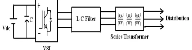
[image:1.612.148.478.619.705.2]The generally DVR consists of energy storage unit, injection transformer, inverter circuit and filter unit
A specially designed transformer that is Injection transformer which limit the transient energy from primary side to secondary side and noise coupling The purpose of storage devices(dc battery) is to supply the necessary energy to the Inverter through a dc link to inject voltage. The Voltage Source Inverter (VSI) from the energy storage battery unit converts the dc voltage to controllable three phase ac voltage. The inverter switches are fired by a sinusoidal Pulse Width Modulation (PWM) technique.
V. LOCATION OF DVR
The location of DVR, fig 2 shows actual location of DVR in system.
[image:2.612.184.414.169.338.2]
Fig. 2. Typical location of DVR
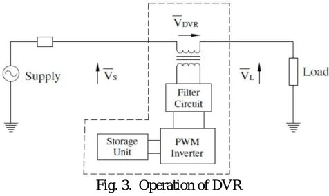
VI. PRINCIPAL OF OPERATION
The DVR is inject dynamically controlled voltage in series with line. Whenever voltage sag or swell occred PI controller detect error signal this signal is given to pulse with modulator generator which generate pulse signals according to error signal and this pulse gives trigger to VSI. VSI convert stored DC voltage into three phase ac according to gate pulse signal. This three phase voltage is then injected to system through ingected transformer.
Fig. 3. Operation of DVR
VII.COMPENSATION OF VOLTAGE SAG USING DVR WITH PI CONTROLLER
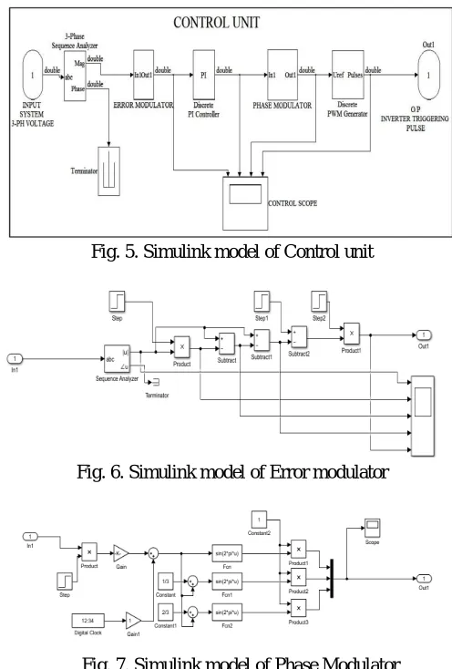
A proportional-integral (PI) controller runs the system to be controlled by a calculating the error which is sum of difference between the sensed output and desired reference and the integral of that value. The integral term of PI controller causes the steady-state error to become zero for a step input. The actuating input signal of PI controller is the difference between Vref and V.. The controller output is given to Pulse Width Modulation (PWM) which generate desired firing sequence. The sinusoidal signal control voltage is phase modulated by using the angle six and the modulated three-phase voltages are:
VA = 1*Sin (mt +6) (1)
VB= 1*Sin(mt+6+2n/3) (2)
[image:2.612.184.422.434.576.2]VIII.MATLAB SIMULINK MODEL
This project aim: To mitigate the voltage sag occurred in load side due to occurrence of different fault in system. DVR with PI control technique is ued for compensation the sag voltage:
[image:3.612.199.419.119.327.2]Fig. 4. Simulink model of test system with DVR implemented
Fig. 5. Simulink model of Control unit
Fig. 6. Simulink model of Error modulator
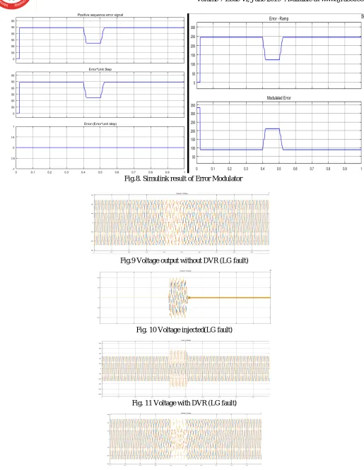
[image:3.612.179.427.358.725.2]Fig.8. Simulink result of Error Modulator
Fig.9 Voltage output without DVR (LG fault)
Fig. 10 Voltage injected(LG fault)
Fig. 11 Voltage with DVR (LG fault)
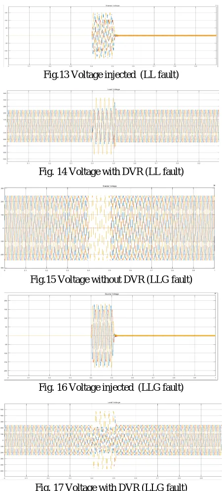
Fig.13 Voltage injected (LL fault)
Fig. 14 Voltage with DVR (LL fault)
Fig.15 Voltage without DVR (LLG fault)
Fig. 16 Voltage injected (LLG fault)
Fig. 17 Voltage with DVR (LLG fault)
IX.CONCLUSION
The design of DVR using both PI Controller proved to be efficient as compared to conventional methods for Power Quality improvement. DVR system design with Fuzzy Logic Controller is the best option for electric utility to evaluate, characterize and access system performance for satisfying the Power Quality needs of distribution system. Enforcement of Power Quality standards and Identifying Power Quality problems in an electric power distribution network, before any extensive damage occurs, is advisable.
REFERENCE
[1] Bhaskar, M. A., Dash, S. S., et al. “Voltage Quality improvement using DVR”, International Conference on Recent Trends in Information, Telecommunication and Computing, pp.378-380, 2010
[2] Prakash, N., Jacob, J., et al, “Comparison of DVR Performance with Sinusoidal and Space Vector PWM Techniques”, International Conference on Magnetics, Machines & Drives, 2014.
[3] Szabo, D., Bodnar, R., et al, “Designing and Modeling of DVR in MATLAB”, IEEE, 2014