A Phase Field Model of Sintering with Direction-Dependent Diffusion
Jie Deng
+Department of Scientific Computing, Florida State University, Tallahassee, FL 32306, U.S.A.
A phasefield model of sintering with direction-dependent interface diffusion is presented, in which the surface and grain boundary diffusions occur along the tangent of surfaces and grain boundaries, respectively. Compared with previous phasefield models of sintering, the proposed model is more consistent with the sharp interface model regarding the directions of interface diffusions. Numerical simulations show that the direction of interface diffusion is critical to model sintering kinetics and morphological evolution, and the performance of phasefield model is improved significantly with appropriate interface diffusion directions. The proposed model is able to capture relevant features of sintering such as neck growth and its dependence on particle size, interface energies and mobilities. These features agree well with theoretical predictions. [doi:10.2320/matertrans.M2011317]
(Received October 11, 2011; Accepted November 15, 2011; Published January 25, 2012)
Keywords: sintering, phasefield method, interface diffusion
1. Introduction
Sintering is a complex process that involves multiple diffusion mechanisms whose relative importance varies with the microstructural evolution.1,2) Since it is one of the most important approaches to transfer particles into ceramics, modeling sintering process gains a lot of interests in research. Current models for sintering can be broadly categoried into sharp and diffuse interface models. In both models, microstructures evolve to reduce the total free energy of a system. They differ mainly in the assumption of interface thickness and the way to characterize interface motion.
In sharp interface models,310) the interface thickness is
zero and the motion of interface is described by the kinetic law. The interface velocity can be written as v¼vsþ
vgþvv, where vs, vg and vv is the velocity contributed by
surface diffusion, grain boundary diffusion and volume diffusion, respectively. These velocities are obtained from the flux of materials such that vs¼ rsJs, vg¼
rgJgandvv¼ Jvn, where³is the atomic volume
andnis the unit vector normal to the interface.Js,Jg andJv
are the material fluxes along free surfaces, along grain boundaries and from bulk to free surfaces or grain boundaries, respectively.rs andrgare the gradients along free surfaces and along grain boundaries, respectively. Solving these equations together with the corresponding boundary con-ditions captures multiple relevant features of sintering such as sintering kinetics and morphological evolution of particles and pores. Nevertheless, since the sharp interface model needs to track the motion of interface explicitly, it becomes inconvenient when the geometry of interface is complex.
In parallel to sharp interface models, the diffuse interface model (i.e., phase field model) of sintering has been developed as well1115) due to its capacity of handling arbitrarily complex geometries. It was shown that the phase
field model is able to evaluate the sintering rate and reveal the microstructure evolution such as neck formation and pore shrinkage during sintering. On the other hand, since diffuse interface in phase field models is an assumption and the
actual interface is much thinner, it is important to check if the phasefield model approaches the sharp interface model as the interface thickness becomes small. It can be shown that previous phase field models of sintering are able to recover the volume diffusion in the sharp interface model, but the surface and grain boundary diffusions have different forms due to their directions. In the present work, we propose a modified phase field model that is more consistent with the sharp interface model regarding the direction of interface diffusions.
In the following, the modified phase field model is presented in Section 2, which includes the comparison of this model with previous phase field models. Section 3 focuses on the numerical simulation of the modified phase
field model, which demonstrates the influence of the direction of interface diffusions on morphological change, and shows the effects of partical size, interface energies and mobilities on the sintering kinetics. The conclusion is given in the last section.
2. Phase Field Model of Sintering
The model presented in this work is based on the previous phase field models shown in Refs. 1114). In this model, microstructure of materials is represented by two types of
field variables. Thefirst type is the conserved densityfieldµ that equals to 1 at the solid phase and 0 at pores. At the free surface of solids,µchanges from 1 to 0 rapidly but smoothly. The other type is the non-conserved order parameter ©i,
which is used to distinguish different grains or particles in the solid phase such that ©i=1 in the i-th grain and 0 in
other grains. At grain boundaries, the corresponding order parameter changes from 1 to 0 or from 0 to 1 smoothly. Based on thesefield variables, the free energy functional of a system can be written as
F ¼
Z
V
fðµ;f©igÞ þ 1 2¢µjrµj
2þX
i 1 2¢©jr©ij
2
" #
dV; ð1Þ
where ¢µ and ¢© are the gradient coefficients related to surface energy and grain boundary energy, respectively. fðµ;f©igÞ is the local free energy density that defines the homogeneous coexisting phases, which has the form
+Corresponding author, E-mail: jd04e@my.fsu.edu. Present address:
Sandia National Laboratories, Livermore, CA 94550, U.S.A.
f¼Aµ2ð1µÞ2þB
"
µ2þ6ð1µÞX i
©2 i
4ð2µÞX i
©3 i þ3
X
i ©2
i
2#
; ð2Þ
where A and B are constants. The evolution equations ofµ and©iare the CahnHilliard equation16)and the AllenCahn
equation,17)respectively, which can be expressed as
@µ
@t ¼ r Mr
¤F
¤µ ¼ r Mr®µ ¼ r Mr
@f
@µ¢µr
2µ
;
ð3Þ
@©i
@t ¼ L
¤F
¤©i
¼ L®©i ¼ L @@f© i
¢©r2©i
; ð4Þ
where L is the mobility coefficient related to the grain boundary migration andMis the mobility tenser contributed by different diffusion mechanisms. Same as the sharp interface model of sintering, three types of diffusions are considered andMcan be written as
M¼MsfsTsþMgfgTgþMvfvI; ð5Þ
whereMs,MgandMvare the mobility coefficients determined
by the diffusivities in surface, grain boundary and volume diffusion, respectively. In eq. (5),fs,fgandfvare functions of field variables that specify the positions where each type of diffusion occurs. According to Ref. 14), we may set fs¼ µð1µÞ,fg¼
P
i
P
j6¼i©i©jandfv¼µ3ð1015µþ6µ2Þ,
so that surface, grain boundary and volume diffusion occurs only at free surfaces, grain boundaries and bulk region, respectively.Iin eq. (5) denotes the identity tensor.TsandTg
are the projection tensors that constrain the direction of surface and grain boundary diffusion, respectively. They are constructed based on the definition of interface gradient such that
Ts¼Insns and Tg¼Ingng; ð6Þ
where ns¼jrrµµj and ng¼
r©ir©j
jr©ir©jj are the unit vectors normal to the free surface and grain boundary, respectively. From eq. (6) we can see thatTsand Tgconstrain the surface
and grain boundary diffusion to occur along the tangent of free surface and grain boundary, respectively.
The present model differs from previous phase field models of sintering in that it adopts the projection tensors to constrain the direction of interface diffusions. In previous models,1114) the mobility in CahnHilliard equation is a
scalar such thatM¼MsfsþMgfgþMvfv. The asymptotic
analysis on this equation shows that it approaches the Hele-Shaw model in its sharp interface limit,18,19)which indicates
that the surface and grain boundary diffusion occurs normal to the surface and grain boundary, respectively. This is different from the sharp interface model where interface diffusion occurs along the tangent of the interface. In order to reduce the mismatch between two models, we introduce the projection tensors to constrain the directions of interface diffusions. It can be shown2022) that after considering the
projection tensors, the interface diffusion occurs along the tangent of the interface, which is consistent with the sharp interface model. It is noted that eq. (3) is similar to the Eulerian expression of the surface partial diffential
equa-tion,2325) and the advantage of eq. (3) is that it can be
computed on a Cartesian grid and capture the correct directions of interface diffusions simultaneously.
3. Numerical Simulation
In this section, we demonstrate the influence of the direction of interface diffusions on the morphological change and neck growth during sintering. We first illustrate the role of the projection tensor in the material fluxes and micro-structure evolution, and then validate the model by showing the effects of size, interface energies and interface mobilities on the sintering kinetics. In phasefield simulations, we solve eqs. (3) and (4) using the finite difference method in two-dimensional space with mesh 300©300 and time step 10¹5.
The values of the dimensionless parameters used in simulations are:A¼16,B ¼1; L¼10,M*
s ¼4,Mg¼ 0:4,M*
v ¼0:01;¢µ¼10,¢© ¼2. Some simulations choose
different parameter values to show the effect of interface energy or mobility, and those values will be specified later. According to Ref. 14), above selection of parameters yields a ratio of surface to grain boundary energy of 1.5 and a diffusivity ratio of 100 : 10 : 1 along the surface, grain boundary and inside of the volume, respectively.
3.1 Effects of the direction of interface diffusion on sintering
[image:2.595.63.238.74.139.2]A configuration where two particles sharing a grain boundary shown in Fig. 1(a) is used to illustrate the effect of projection tensor on surface diffusion. Initially each particle has hexagon shape with the same size. We take the surface diffusion as an example since the role of projection tensor on surface diffusion is essentially the same as that on grain boundary diffusion. Figures 1(b) and 1(c) show the distribution of materialfluxes without and with the projection tensor for the configuration shown in Fig. 1(a). It can be seen that, without the projection tensor, although surface diffusion is constrained to occur only at the surface, its direction is not well captured since it occurs normal to the surface. In contrast, after including the projection tensor, both position and direction of the surface diffusion are well captured such that the surface diffusion moves materials from the high curvature region to low curvature region along the tangent of surface. Moreover, comparing Figs. 1(b) and 1(c) it is found that the magnitude of material flux is indpendent of the surface curvature in the former but proportional to the gradient of the surface curvature in the latter. This is another advantage of using the projection tensor such that the materialflux is proportional to its driving force.
substantially after including the projection tensor, where surface diffusion attempts to minimize the curvature differ-ence along the surface and drive the system to approach equilibrium.
Above simulations consider the surface diffusion only. The role of projection tensor is also apparent when all diffusion paths are activated. The initial configuration in this case is given by Fig. 3(a), which represents an intra-splat microcrack and is similar to the one used in Ref. 10). The morphological change with the consideration of projection tensors is given by Figs. 3(b) and 3(c). It shows that, as sintering proceeds, the surface of particles becomes smooth and the shape of particles as well as cracks become circular. It also shows that the morphological change is more rapid in higher curvature region, an important feature of sintering. Moreover, the neck between two particles grows steadily and the dihedral angle is kept as a constant at the tips of the grain boundary. The constant dihedral angle is expected since it is determined by the ratio of surface energy to grain boundary energy, and both energies do not change during the simulation. For the purpose
of comparison, the morphology of particles without projec-tion tensors is given by Fig. 3(d). It can be seen that, without appropriate direction of interface diffusion, the microstruc-ture evolution cannot be well capmicrostruc-tured and the neck growth nearly ceases. Thus, Fig. 3 demonstrates that appropriate treatment of interface diffusion is crucial for characterizing the kinetics and morphological change during sintering.
3.2 Effects of the size, interface energies and mobilities on sintering
In order to validate the proposed phase field model, we investigate the neck growth and its dependence on partical size, interface energies and mobilities. The initial confi g-uration is given by Fig. 3(a), and it is noted that previous models fail to capture sintering in this case [see Fig. 3(d)]. A typical neck growth obtained by the proposed model is shown in Fig. 4(a), where the relative neck length is the ratio of the neck lengthxto the initial height of the rectanglea. It is found that the neck growth can be divided into two stages. In each stage, the neck growth follows a power law
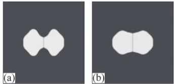
Fig. 2 Morphology of particles under surface diffusion (a) without and (b) with the projection tensor after dimensionless time 300.
Fig. 3 Morphological evolution of particles when all diffusion paths are activated. The projection tensors are considered in (a), (b), and (c). The sintering time is: (a) 1; (b) 200; (c) 300; (d) 300.
(a) (b)
Fig. 4 (a) Neck growth as a function of time. Early and late stage of growth exhibits power law scaling with different exponents; (b) Neck growth under different grain boundary to surface energy ratios. Insertedfigures show the particle morphology after the same sintering time.
[image:3.595.48.292.69.149.2] [image:3.595.340.512.70.153.2] [image:3.595.122.471.205.283.2] [image:3.595.137.459.338.489.2]ðx=aÞn/t, and the exponent n in the early stage is smaller than it in the late stage. The initial high growth rate is due to the large curvature variation at the bottom of the crack, which results large driving forces for neck growth. As sintering proceeds, the surface becomes smoother and then the neck growth rate decreases. The theoretical value ofnvaries from 3 to 7 depending on the type of diffusion mechanism.2)Our data shows thatn=3«0.5 for early stage andn=5«0.5 for later stage, which is reasonable since various diffusion mechanisms are activated.
The effect of interface energy is given by Fig. 4(b), which shows the neck growth and morphology of particles under different grain boundry to surface energy ratio£g=£s. Since £g and £s is proportional to the square root of the gradient
coefficient¢© and¢µ, respectively, adjusting the ratio¢©=¢µ is able to change the energy ratio £g=£s. The particle
morphology shown in Fig. 4(b) is obtained after the same sintering time. It can be seen that lower£g=£scorresponds to
larger dihedral angle º, which reflects the relation cosº¼ £g=ð2£sÞand indicates that£g=£sdetermines the equilibrium
shape of particles. In addition, Fig. 4(b) also shows that increasing £g=£s decreases the neck growth rate, which is
similar to the results obtained from sharp interface mod-els.5,7,9)
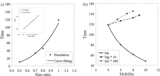
The dependence of neck growth on particle size is given by Fig. 5(a), which shows the time needed to reach 60% of the
final neck length for different particle sizes. The reference configuration is given by Fig. 3(a), and the size ratio is the ratio of the actual configuration to the reference one. As expected, the particle with smaller size sinters faster, which is consistent with the Herring’s scaling law.1,26)Moreover, it is
found that the sintering rateR has a power law scaling with particle size, R/am, where m¼3:54. The theoretical
value ofmis 4 for surface and grain boundary diffusion, and 3 for volume diffusion.1,26) The value of m obtained from simulation is between these theoretical values since all three diffusion mechanisms are involved.
Figure 5(b) illustrates the effect of the mobilities (Ms,Mg
and Mv) on neck growth. In thisfigure, when one mobility
varies, the other two are fixed. Figure 5(b) shows that increasing surface mobility accelerates the neck growth. This is because surface diffusion attempts to minimize the curvature variation along the surface, so higher surface
diffusion drives more materials to the tips of necks, resulting faster neck growth. Increasing grain boundary mobility, on the other hand, decreases the growth rate, which is consistent with the previous work on sharp interface model7,9)such that increasing the grain boundary to surface diffusivity ratio increases the sintering time. Figure 5(b) also shows that increasing volume diffusion decreases the neck growth rate. This is due to more of the driving force for diffusion being consumed by the volume diffusion (which causes no neck growth) and hence being unavailable to promote the surface diffusion.
From above results we can see that, after taking into account the appropriate directions of interface diffusions, the proposed model is able to capture essential features of sintering.
4. Concluding Remark
A phase field model of sintering with appropriate directions of interface diffusions has been developed. Numerical simulations show that it is critical to have correct interface diffusion directions in order to capture the kinetics and morphological evolution during sintering. A variety of relevant features of sintering have been captured by the proposed model, which include the neck growth law and its dependence on particle size, interface energy and various mobilities. These features are consistent with the theoretical predictions and demonstrate the important role of the directions of interface diffusions in phase field model of sintering.
Acknowledgement
Author appreciates valuable discussions with Dr. Anter El-Azab at Florida State University. Author thanks the support from the Florida Center for Advanced Aero-Propulsion (FCCAP).
REFERENCES
1) S. Kang:Sintering: Densification, Grain Growth and Microstructure, (Elsevier Butterworth-Heinemann, Oxford, 2005).
2) R. German:Sintering Theory and Practice, (Wiley-Interscience, New
(a) (b)
[image:4.595.138.460.67.221.2]York, 1996).
3) J. Svoboda and H. Riedel:Acta Metall. Mater.43(1995) 499506. 4) J. Svoboda and H. Riedel:Acta Metall. Mater.43(1995) 110. 5) W. Zhang and J. Schneibel:Acta Metall. Mater.43(1995) 43774386. 6) J. Pan and A. Cocks:Acta Metall. Mater.43(1995) 13951406. 7) J. Pan, H. Le, S. Kucherenko and J. Yeomans:Acta Mater.46(1998)
46714690.
8) A. Maximenko and E. Olevsky:Acta Mater.52(2004) 29532963. 9) F. Parhami, R. McMeeking, A. Cocks and Z. Suo:Mech. Mater.31
(1999) 4361.
10) A. Cipitria, I. Golosnoy and T. Clyne:Acta Mater.57(2009) 980992. 11) A. Kazaryan, Y. Wang and B. Patton:Scr. Mater.41(1999) 487492. 12) Y. Wang and Y. Liu:J. Am. Ceram. Soc.83(2000) 22192226.
13) X. Jing, J. Zhao and L. He:Mater. Chem. Phys.80(2003) 595598.
14) Y. Wang:Acta Mater.54(2006) 953961.
15) K. Asp and J. Agren:Acta Mater.54(2006) 12411248.
16) J. Cahn and J. Hilliard:J. Chem. Phys.28(1958) 258267. 17) S. Allen and J. Cahn:Acta Metall. Mater.27(1979) 10851095. 18) R. Pego:Proc. Roy. Soc. London Ser. A422(1989) 261278. 19) N. Alikakos, P. Bates and X. Chen:Arc. Rat. Mech. Anal.128(1994)
165205.
20) J. Cahn, C. Elliott and A. Novick-Cohen:Euro. J. Appl. Math.7(1996) 287301.
21) M. Mahadevan and R. Bradley:Phys. D126(1999) 201213. 22) D. Bhate, A. Kumer and A. Bower:J. Appl. Phys.87(2000) 1712
1721.
23) M. Bertalmio, L. Cheng, S. Osher and G. Sapiro:J. Comput. Phys.174 (2001) 759780.
24) J. Xu and H. Zhao:J. Sci. Comput.19(2003) 573594.