CONTINUOUSLY FREQUENCY-TUNABLE CW
OPTICAL PARAMETRIC OSCILLATORS AND THEIR
APPLICATION TO SPECTROSCOPY
Graham Martin Gibson
A Thesis Submitted for the Degree of PhD
at the
University of St Andrews
1999
Full metadata for this item is available in
St Andrews Research Repository
at:
http://research-repository.st-andrews.ac.uk/
Please use this identifier to cite or link to this item:
http://hdl.handle.net/10023/14950
Continuously frequency-tunable cw
optical parametric oscillators and their
application to spectroscopy
G. M. Gibson
Omo
J.F. Allen Physics Research Laboratories, Department o f Physics & Astronomy,
University o f St. Andrews, Fife, Scotland.
A thesis submitted to the University of St. Andrews in application for the degree of Doctor of Philosophy
ProQuest Number: 10166482
All rights reserved
INFORMATION TO ALL USERS
The quality of this reproduction is dependent upon the quality of the copy submitted.
In the unlikely event that the author did not send a com plete manuscript and there are missing pages, these will be noted. Also, if material had to be removed,
a note will indicate the deletion.
uest
ProQuest 10166482
Published by ProQuest LLO (2017). Copyright of the Dissertation is held by the Author.
All rights reserved.
This work is protected against unauthorized copying under Title 17, United States C ode Microform Edition © ProQuest LLO.
ProQuest LLO.
789 East Eisenhower Parkway P.Q. Box 1346
-1
Declarations
I, Graham Martin Gibson, hereby certify that this thesis, which is approximately
22,000 words in length, has been written by me, that it is the record of work carried
out by me and that it has not been submitted in any previous application for a higher
degree.
Date ^ ^ Signature of candidate
I was admitted as a research student in September 1995 and as a candidate for the
degree of Doctor of Philosophy in September 1995; the higher study for which this
is a record was carried out in the University of St. Andrews between 1995 and 1998.
I hereby certify that the candidate has fulfilled the conditions of the Resolution and
Regulations appropriate for the degree of Doctor of Philosophy in the University of
St. Andrews and that the candidate is qualified to submit this thesis in application for
that Degree.
Date ^ ^ ? Signature of supervisors______________________
In submitting this thesis to the University of St. Andrews 1 understand that I am
giving permission for it to be made available for use in accordance with the
regulations of the University Library for the time being in force, subject to any
copyright vested in the work not being affected thereby. I also understand that the
title and abstract will be published, and that a copy of the work may be made and
supplied to any bona fide library or research worker.
Acknowledgements
I would firstly like to thank my supervisors, Professor Malcolm Durm and Dr Miles
Padgett, for their continued support and guidance over the last three years at St.
Andrews. Their enthusiasm and commitment has been much appreciated.
I would like to thank the members of the research groups in the department that have
been involved in collaboration work related to my PhD. I am grateful to the
members of the Microchip Lasers group, Bruce Sinclair, Alan Kemp, and in
particular Richard Conioy, for their co-operation in the collaborative work on the
Cw Microchip-Laser Pumped OPO. I would also like to thank Graham Turnbull and
Majid Ebrahimzadeh for their co-operation in the collaborative work on the
Difference Frequency Generation in PPKTP. I am grateful to Majid for securing the
collaboration with Hâkan Karlsson and Fredrik Laurell on the PPKTP sample.
I would like to thank Cameron Rae for his help and advice on OPOs, and for the
loan of equipment used in the experiments. I tliank Gary Morrison for his help and
support as a Research Assistant during the first year of my PhD.
I am grateful to the members of the CW-OPO group: Tom Edwards, Ian Lindsay,
David Stothard and Graham Turnbull for their valuable discussions and advice
Finally I would like to thank the other members of the Optical Science and
Instrumentation group, both past and present, without whom my tluee years in St.
Andrews would just not have been the same: Jochen Arlt, Mark Begbie, Johannes
Courtial, Kishan Dholakia, Jacqueline Hewett, Paul Lesso, Tracy McKechnie, Anna
A Tunable Laser Source for Spectroscopy
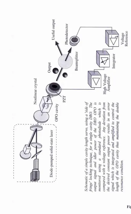
Continuous Wave Optical Parametric Oscillators (cw OPOs) are solid-state sources
of coherent light with broad tuning ranges. Applications of such devices include,
quantum optics experiments, optical frequency division, and high-resolution
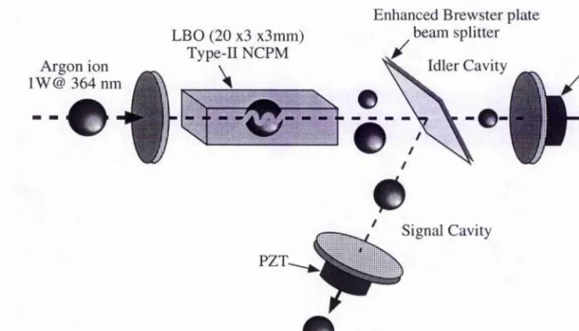
spectroscopy. The doubly resonant OPO shown above provided single frequency
light, around 1 pm, that was coarsely tunable over ~50nm and smoothly tunable over
~5GHz. This configuration was used to demonstrate the DRO as a spectroscopic
source by recording the transmission spectrum of the cesium molecule (Cs]) in the
Doubly Resonant Optical Parametric Oscillator (DRO)
The DRO is stabilised using a cavity length servo system. The output power is
monitored using a photodiode and a piezoelectric transducer provides the correction
of the cavity length to maintain a constant output power and operation on a single
mode-pair. This system maintains a constant cavity length to better than 0.5nm.
Once stabilised, the DRO has the combination of good frequency selectivity and low
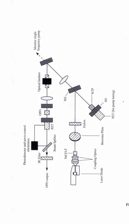
All Solid-State, Diode-Pumped, Laser Source for OPOs
The OPO pump source comprises of a diode-pumped Nd:YLF laser with an
intracavity KTP frequency doubler. This provides a few hundred milliwatts of
single frequency light at 523nm. Piezoelectric control of the cavity length provides
Compact Microchip Laser Pump Source for OPOs
An ultra-compact frequency-doubled microchip laser, based on a sandwich of
Nd:YV04 and KTP, has been demonstrated as an alternative pump source for DROs.
The OPO operated on a single mode-pair even when pumped using a
multilongitudinal-mode laser. Such pump lasers, when combined with compact
Abstract
This thesis describes the development and applications of single-frequency,
continuously tunable, continuous-wave (cw), optical parametric oscillators (OPOs).
Two doubly-resonant OPOs (DROs) are presented, one providing tunable light
around 1pm, the other specifically designed as a spectroscopic source for methane
near 1649mii. Once stabilised, the frequency-selective nature of the DRO ensures
operation on a single mode-pair without the need for additional intracavity
frequency-selective components. Both DROs are smoothly tunable by smoothly
tuning the pump laser.
The 1pm DRO is based on a bulk KTP crystal cut for near-degenerate, type-II,
critical phase-matching (0 = 90°, (j) = 37°). Angle tuning the crystal provides coarse
tuning of the output frequencies over a range of ~50nm. Small perturbations to the
OPO cavity is sufficient to cause a systematic mode-hop and provides a method of
tuning across the phase-matching bandwidth (~0.5THz). This DRO is demonstrated
as a spectroscopic source by recording the absorption spectrum of cesium molecules
near lOSOnm.
The DRO as a potentially compact source of tunable light is demonstrated by using a
frequency-doubled microchip laser as the pump source. The output consists of a
single pair of signal and idler modes even when using a multilongitudinal-mode
pump laser. Smooth tuning of the output frequencies is achieved by temperature
The 1.65(im DRO is based on periodically poled KT10P04 (PPKTP). The
suitability of PPKTP for cw OPOs was first assessed by a difference frequency
generation experiment from which the effective d]3 coefficient was estimated to be
~5pm/V. The idler wavelength is coarsely tuned at a rate of 0.73nm/°C by varying
the crystal temperature.
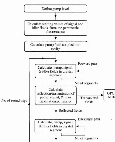
A combination of computer modelling and experimental observation is used to study
the dynamic behaviour of a DRO, The numerical model calculates the time required
for the OPO to build-up from the parametric fluorescence and is in excellent
Outline of the work within the thesis
Chapter 1 introduces the optical parametric oscillator as a source of tunable,
coherent light and gives a brief history of the development of cw OPOs. It has only
been in the last few years, with advances in pump lasers and new nonlinear optical
materials, that many new cw OPO configurations have been investigated.
Chapter 2 gives the theoretical background starting with the parametric down
conversion process and arriving at the three coupled equations which describe the
pump, signal, and idler fields as they propagate through a nonlinear medium. The
different cavity configurations for OPOs are discussed in terms of their associated
pump power thresholds and stability requirements. A few different experimental
OPO set-ups are discussed with the emphasis being on the single-cavity, doubly-
resonant OPO (DRO) with single mode-pair output. Smooth, continuous frequency
tuning from a single cavity DRO is also discussed.
Chapter 3 describes the experimental configuration of a cw, near degenerate, DRO
operating in the Ijim spectral region. This OPO is based on a previously reported
configuration and forms the basis of the main experimental work within this thesis.
Chapter 4 describes the study of the dynamic behaviour of a DRO using a
combination of computer modelling and experimental observation. The computer
with the numerical modelling. The model is then used to predict the dynamic
behaviour of systems for various design parameters of DROs and the implications
this has on their stability. This work has been published in Optics Communications.
Chapter 5 reports the application of a smoothly-tunable, single-frequency, cw, OPO
for high-resolution spectroscopy. The OPO is based on KTP and resonant for both
signal and idler fields resulting in a device with a very low pump power threshold of
30mW. It is shown that the extremely stringent operating conditions normally
associated with DROs aid the DRO in terms of single frequency output and smooth
frequency tuning. This frequency selective nature ensures that the signal and idler
modes can be tuned across the phase-matched bandwidth without the need for
additional intracavity frequency selective components. Smooth frequency tuning of
the OPO output is obtained by tuning the pump laser. The practicality of the OPO is
demonstrated by recording the transmission spectrum of the cesium molecule (Csa)
in the lp,m spectral region. Mode-hopping, wliich has long been regarded as a major
disadvantage in DROs, can be successfully controlled to provide a reliable means of
tuning over the phase-matched bandwidth of the nonlinear material. The
introduction of tuning by mode-hopping bridges the gap between the coai'se tuning
of the OPO and the fine tuning of the pump laser. This allows access to any
wavelength that lies within the phase-matched bandwidth (~0.5THz), This work has
Chapter 6 reports a DRO pumped by an ultra compact, frequency doubled, cw,
microchip laser. The frequency selective properties of the DRO, as discussed in
chapter 5, result in single frequency output even when using a multimode pump
laser. Veiy compact, low threshold (typically lOmW), DROs of monolithic design
have already been demonstrated. These very low tlireshold DROs, along with
compact pump sources, provide the opportunity of developing very compact sources
of tunable coherent light. The work on the microchip-laser pumped OPO was
completed in collaboration with Richard Conroy at the University of St. Andrews
and published in Optics Letters,
Chapter 7 reports a difference frequency generation experiment using the new
nonlinear optical material periodically poled KTi0P04 (PPKTP). While KTP cut
for type-II biréfringent phase-matching is relatively insensitive to temperature,
quasi-phase-matched KTP shows a useful degree of temperature tuning. An output
power of 12jLiW around 1.6p.m was generated by difference-frequency mixing the
outputs of a frequency doubled Nd:YLF laser at 523nm (240mW) and a tunable
Ti:sapphire laser near 760nm (340mW). The temperature tuning rate is consistent
dft
with the theoretical predictions based on Sellmeier and — data. These theoreticaloT
predictions have been extended to assess the suitability of PPKTP as a nonlinear
optical material for practical applications. The work on difference frequency
generation was completed in collaboration with Graham Turnbull at the University
Chapter 8 reports a cw, single-frequency, DRO based on PPKTP. This OPO has
been specifically designed as a single-frequency source operating around 1.65|U,m for
spectroscopic applications. A maximum output power of lOmW at 1.65p,m was
obtained for a pump power of -200mW at 523nm. The practicality of the OPO is
demonstrated by recording the transmission spectrum of methane near 1649nm.
This chapter discusses the importance of the mismatch in the free spectral ranges,
AFSR, in terms of easily stabilising the OPO to obtain operation on a single pair of
signal and idler modes. This work has been accepted for publication in Optics
Contents
1 Introduction... 18
1.1 OPOs as sources of tunable light...18
1.2 A brief history of the development of cw OPOs...22
1.3 References... 27
2 Theoretical background... 29
2.1 Optical parametric generation...29
2.2 The nonlinear interaction...32
2.3 Optimum focussing for nonlinear interactions... 35
2.4 The coupled amplitude equations... 37
2.5 Biréfringent phase-matching... 38
2.6 Quasi-phase-matching...42
2.6.1 Quasi-phase-matching tolerances... 46
2.7 Doubly resonant oscillators... 49
2.7.1 Pump power thresholds for DROs...49
2.7.2 Stability requirements for single mode-pair operation of DROs...59
2.8 The singly resonant oscillator (SRO)...64
2.8.1 Pump power thresholds for SROs ... 64
2.9 Continuous frequency tuning of DROs... 68
2.10 Summary and conclusions... ...73
2.11 References... ..74
3 A continuous wave, continuously tunable, single frequency, doubly resonant OPO ... 77
3.1 Introduction. ... 77
3.2 Experimental observations of a KTP OPO (type-II phase-matching)...81
3.3 Smooth/continuous frequency tuning...87
3.4 Summary and conclusions... 87
3.5 References...88
4 Dynamic behaviour of a doubly resonant optical parametric oscillator...89
4.1 Introduction...89
4.2 Modelling the dynamic behaviour of a DRO... 91
4.3 Experimental configuration ... 98
4.4 Comparison of experimental and modelled results ...101
5 The application of a continuously ^tunable, cw, optical parametric oscillator
for high resolution spectroscopy... 113
5.1 Introduction... 113
5.2 Frequency selective properties of a stabilised DRO... 115
5.3 Experimental configuration... 117
5.4 Summary and conclusions...126
5.5 References... 127
6 Microchip laser pumped cw doubly resonant OPO...130
6.1 Introduction... 130
6.2 Experimental configuration...131
6.3 Summary and conclusions ...138
6.4 References...139
7 Temperature tuned difference frequency mixing in periodically poled KTIOP04...141
7.1 Introduction...141
7.2 Experimental configuration... 142
7.3 Summary and conclusions... 149
7.4 References... 150
8 A continuous-wave optical parametric oscillator based on periodically poled KT10P04 and its application to spectroscopy...152
8.1 Introduction... 152
8.2 Stability requirements for single mode-pair operation of DROs...153
8.3 Experimental configuration... 156
8.4 Summary and conclusions... 162
8.5 References ... 164
9 Summary and Conclusions...165
10 Appendices...167
10.1 Appendix A. Program Listing... 168
10.2 Appendix B. Summary of Pump Power Thresholds...180
10.3 Appendix C. Error Signal Circuit for Stabilising DROs... 181
1 Introduction
1.1 OPOs as sources of tunable light
Lasers have long been regarded as sources of high intensity, coherent, and highly
directional radiation operating at well defined wavelengths. The highly
monochromatic nature of laser radiation results from the presence of discrete energy
levels within the atoms or molecules in the laser medium. For many laser
applications the exact wavelength of the radiation is not important but there are a
few applications, e.g. spectroscopy, that require a well defined range of wavelengths.
Spectroscopy, in particular, requires the laser to be tuned to a particular frequency
and then tuned through a resonance. There already exists a number of techniques to
provide tunable sources of laser radiation using gain media with broadened energy
bands. Two examples of such laser media are organic dyes and titanium doped
sapphire. Although such tunable lasers are often pumped by conventional laser
sources, this is simply to optically excite the lasing transition and the degree of
coherence of the pump source has little bearing on the output of the tunable laser
itself.
There exists a number of nonlinear techniques for frequency shifting tlie radiation of
a laser beam. It was not until the advent of the laser that nonlinear techniques such
as harmonic generation, sum frequency mixing and optical parametric generation ^
original pump laser. Optical parametric generation is a process where a pump
photon, propagating in a nonlinear optical material, is converted into two new
photons termed the signal and the idler.
Pump Photon
Idler Photon
Signal Photon
Figure 1.1 Considering the nonlinear interaction in terms of photons the
parametric down conversion process can be thought of as a pump photon being split
into tw>o new photons, signal and idler, within the nonlinear optical crystal such that
the photon energies is conserved. By convention, the lower energy photon is called
the idler.
This process takes place such that the photon energy conservation relation is obeyed.
The resulting pair of frequencies is determined by the momentum conservation
relation which maintains the relative phase between the pump, signal, and idler. The
momentum conservation relation, or more commonly the phase-matching condition,
requires that the sum of the wave-vectors of the generated photons equals the wave-
vector of the pump photon. Many pairs of signal and idler frequencies, obeying the
provides a source of tunability. The phase-matching condition can be altered (as
described below and in chapter 2) to provide coarse frequency tuning.
The signal and idler fields are generated simultaneously and are coherent and
collinear with the pump beam itself. Within bulk nonlinear optical materials, phase-
matching can be achieved by altering the refractive indices experienced by the signal
and idler fields. This can be achieved by changing either the orientation or
temperature of the nonlinear material and thus forms the basis of coarse tunability of
the coherent light beams.
©
Angie of Crystal sets
splitting ratio
©
e
Temperature of Crystal sets
splitting ratio
Figure 1.2 Momentum conservation results in preferred signal and idler
frequencies. The two most common methods o f controlling the ratio o f the signal
and idler frequencies is to change the angle o f incidence of the pump or temperature
The limitation of this coarse tuning is usually determined by the optical transparency
of the nonlinear material. More recently there has been much interest in engineered
(poled) nonlinear optical materials having a periodic domain structure. Phase-
matching is achieved by choosing an appropriate period of the domain structure and
is commonly referred to as Quasi-Phase-Matching (QPM). The domain period
determines the frequencies of the signal and idler fields. The introduction of these
new improved nonlinear optical materials not only provides greater conversion
efficiency but also allows access to new spectral regions.
t 1 t J Î
\
t
\
t
\
t
\
t
e
©
Period
of Nonlinear Coefficient sets
splitting ratio
Figure 1.3 In the case of the new poled nonlinear materials the ratio o f the
signal and idler frequencies is determined by the period o f the nonlinear domains.
These nonlinear materials are commonly placed within an optical resonator to form a
device known as an optical parametric oscillator (OPO). When the pump field
intensity, fed into the resonator, reaches a critical value, referred to as the pump
the signal or idler frequency, or at both these frequencies. This is determined by the
nature of the mirror coatings at the signal and idler frequencies. The pump source
must also be coherent, unlike the non-coherent sources used to pump conventional
lasers.
The two main configurations for OPOs are pulsed or continuous wave (cw). OPOs
configured as short-pulsed devices are now widely accepted as sources of tunable
coherent radiation with many applications including, spectroscopy and quantum
optics. However, due to threshold constraints and stability requirements, cw OPOs
have still to achieve the same level of acceptance.
1.2 A brief history of the development of cw OPOs
The first demonstration of an OPO was by Giordmaine and Miller, in 1965, ^ and
used a high peak power pulsed laser, wavelength 0.529jiim, as the pump source.
Tunable optical parametric oscillation was observed in lithium niobate (LiNbOs) in
the wavelength range 0.97 to 1.15|im. This pulsed device was followed by the first
report of a cw OPO by Smith et al in 1968 In order to reduce the pump power
threshold to a level compatible to the majority of available laser sources this OPO
was configured as a doubly resonant oscillator (both signal and idler fields resonant).
The doubly resonant OPO (DRO) was based on barium sodium niobate
(Ba2NaNb5 0i5) and was pumped using a frequency doubled Nd:YAG laser.
which was largely due to the competition between the longitudinal modes of the
pump laser.
Attention then turned to singly resonant parametric oscillators (SROs). These were
not constrained to having two discrete frequencies resonating within the same cavity
and hence provided tunable radiation that was stable in amplitude and frequency.
Due to only having one frequency resonant in the OPO cavity, the pump power
threshold for SROs was generally too high for convenient cw pump sources and
hence most of the earlier devices were pulsed. However, high-power NdrYAG
pump lasers resonant pump enhancement and more recently, periodically poled
lithium niobate ^ have enabled cw SRO systems to be operated. Since the mid
1980’s there has been a steady flow of new nonlinear optical materials with higher
laser damage thr'esholds, wider optical transparencies, and relatively large nonlinear
coefficients.
The first demonstration of a pump-enlianced SRO ^ combined the advantages of the
SRO with relatively low pump powers. The required pump power density was
achieved by resonating the pump and one of the generated fields. This OPO was
based on lithium triborate (LiBgO^) and pumped by a single-frequency argon-ion
laser. The OPO operated with a 1 watt threshold at 514.5nm and produced 500mW,
non resonant wave, for a pump power of 3.4W.
Since their initial demonstration, the development of cw OPOs, in particular, lagged
behind that of other sour ces of widely tunable radiation. The constraints of either
the high thresholds associated with SROs, have prevented the widespread use of cw
OPOs. However, advances in pump laser sources ^ and efficient nonlinear
parametric materials achieving ever increasing efficiencies, has allowed many
different types of cw OPOs to be investigated. High pump power tliresholds have
long been regarded as the limiting factor in the design of cw OPOs. However, a cw,
singly resonant, intracavity, OPO has been demonstrated This is based on a singly
resonant potassium titanyl phosphate (KTP) OPO located directly within the cavity
of a Ti:sapphire laser to exploit the high circulating power levels. This produced a
maximum output power of 0.4W and displayed long-term amplitude-stable
operation.
Smooth continuous frequency tuning of a cw DRO, pumped by a fixed frequency
pump laser, was achieved by resonating the nondegenerate signal and idler fields in
different optical cavities. This device known as a dual-cavity OPO allowed
continuous tuning through independent control of the signal and idler cavity lengths.
A smooth tuning range of ~0.4GHz was achieved for the signal around 500nm,
limited by the width of the pump resonance. Smooth frequency tuning of a single
cavity DRO was demonstrated by Henderson et. al. The extra constraint of the
double resonance condition was overcome by using a cavity length servo system to
maintain a constant output power and operation on a single mode-pair. Smooth
tuning of the output frequencies over -5 GHz was achieved by simultaneously tuning
In the 1990’s QPM using engineered nonlinear materials, in particular periodically
poled lithium niobate (PPLN), has resulted in a large increase in the development of
cw OPOs QPM permits access to the highest nonlinear coefficient of the
material (e.g. dss in lithium niobate) hence resulting in greater efficiencies. The
greater efficiencies of these new materials relaxes the pump power requirements of
cw OPOs and hence gives more flexibility in the choice of pump lasers. SROs based
on PPLN, having pump power thresholds of a few watts, have recently been
demonstrated The pump power threshold can be reduced further by enhancing the
pump field within the OPO cavity. A pump enhanced SRO based on PPLN has
recently been demonstrated by Sclmeider et al. This device was pumped by a
single-frequency mmiature Nd:YAG ring laser and operated with a thieshold of
260mW and a smooth tuning range of 2GHz. The increased flexibility of
periodically poled materials has allowed the development of nonlinear devices using
novel grating designs such as the cw PPLN OPO, using a fan-out grating design,
demonstrated by Powers et al.
The new nonlinear optical materials that have recently aided the development of cw
SROs have also generated a renewed interest in cw DROs. For these materials the
predicted pump power thresholds are within the range of available cw diode lasers
and thus provides the opportunity of developing very compact and efficient sources
of tunable radiation. A cw DRO based on PPLN and directly pumped by a
Flux-grown KTP has also been successfully poled Periodically poled KTP
(PPKTP) has the advantages of a high photorefractive damage threshold and low
susceptibility to thermal lensing. PPKTP has recently been demonstrated in a near
degenerate cw OPO This OPO operated near room temperature and was pumped
by a frequency doubled Nd:YAG laser. Chapter 8 describes a cw OPO based on
PPKTP that has been designed as a spectroscopic source for methane transitions near
1649mn.
The high efficiency and compactness of diode-pumped lasers, along with their
excellent frequency stability, make them ideal for frequency conversion in cw
OPOs. OPOs have the capacity to reproduce the spectral and spatial quality of their
pump source. Therefore, the generation of narrow-linewidth radiation from an OPO
is greatly eased by the use of a narrow-linewidth pump source. A renewed interest
in cw OPOs has been accompanied by proposals to incorporate them within specific
experiments for investigation into a variety of research areas: e.g. squeezed states of
1,3 References 1 3 5 6 7 9 10 11
J. A. Armstrong, N. Bloembergen, J. Ducuing and P. S. Pershan, Phys. Rev.
127, 6, 1918(1962).
J. A. Giordmaine and R. C. Miller, Phys. Rev. Lett. 14, 24, 973 (1965).
R. G. Smith, J. E. Geusic, H. J. Levinstein, J. J. Rubin, S. Singh and V.
Uitert, Appl. Phys. Lett. 12, 9, 308 (1968).
S. T. Yang, R. C. Eckardt and R. L. Byer, Optics Lett. 18, 12, 971 (1993),
G. Robertson, M. J. Padgett and M. H. Dumi, Optics Lett. 19, 21, 1735
(1994).
W. R. Bosenberg, A. Drobshoff, J. I. Alexander, L. E. Myers and R. L.
Byer, Optics Lett. 21, 10, 713 (1996).
C. D. Nabors, R. C. Eckardt, W. J. Kozlovsky and R. L. Byer, Optics Lett.
14, 20, 1134(1989).
F. G. Colville, A. J. Henderson, M. J. Padgett, J. Zhang and M. H. Dunn,
Optics Lett. 18, 3, 205 (1993).
F. G. Colville, M. H. Dunn and M. Ebrahimzadeh, Optics Lett. 22, 2,75
(1997).
F. G. Colville, M. J. Padgett and M. H. Dunn, Appl. Phys. Lett. 64, 12,1490
(1994).
A. J. Henderson, M. J. Padgett, J. Zhang, W. Sibbett and M. H. Dunn, Optics
12
13
14
15
17
18
19
20
L, E. Myers and W. R. Bosenberg, IEEE J. Quant. Elect.., 33, 10, 1663
(1997).
K. Sclmeider, P. Kramper, S. Schiller and J. Mlynek, Optics Lett. 22, 17,
1293 (1997).
P. E. Powers, Thomas J. Kulp and S. E. Bisson, Optics Lett. 23, 3, 159
(1998^
L. E. Myers, R. C. Eckardt, M. M. Fejer, R. L. Byer, W. R. Bosenberg and
J. W. Pierce, J. Opt. Soc. Am. B 12, 11, 2102 (1995).
H. Karlsson and F. Laurell, Appl. Phys. Lett. 71, 24, 3474 (1997).
A. Garashi, A. Arie, A. Skliar and G. Rosenman, Optics Lett., 23, 22, 1739
(1998).
S. Reynaud, C. Fabre and E. Giacobino, J. Opt. Soc. Am. B 4, 10, 1520
(1987).
N. C. Wong, Optics Lett. 15, 1129 (1990).
N. C. Wong, Optics Lett. 17, 1155 (1992).
2 Theoretical background
2.1 Optical parametric generation
The optical parametric down-conversion process involves an input pump wave,
propagating in a nonlinear optical material with frequency , being converted into
two output waves, termed the signal and idler, at frequencies and
respectively. This process takes place such that the energy conservation relation is
obeyed i.e.
V p = n + V ,.. [2.1]
The parametric down conversion process can also be described as a pump photon
breaking down into two lower energy photons. For a given pump frequency, there is
a continuous choice of signal and idler frequencies which satisfy the condition of
energy conservation. However, the specific pair of frequencies are determined by
the momentum conservation, or phase-matching condition, which is described by the
wave-vector mis-match Nc. Efficient parametric down-conversion requires that
Iltz
where n^, and are the refractive indices of the pump, signal, and idler fields,
kp, kg, and kj are the corresponding wave-vector magnitudes. For perfect phase-
matching the relative phase between the waves is maintained.
Anisotropic optical materials exhibit birefringence, refractive index dependent on the
polarisation state of the light and direction of propagation. The most common
method of satisfying the phase-matching condition is to make use of this
birefringence to compensate for material dispersion. Within the transparency range
of optical materials, dispersion results in the increase in refractive index with
increasing frequency. This causes the relative phase of the pump, signal, and idler
fields to change with propagation and thus sets a limit on the length of crystal that
can be used. The phase-matching condition becomes more difficult to maintain as
the crystal becomes longer. The effect of imperfect phase-matching on the
efficiency of the nonlinear process is given by
efficiency /^sinc^ [2.3]
V 2 j
This proportionality is related to the function H,n, as defined in Boyd & Kleimnan \
Efficiency
Ak
Figure 2.1 The efficiency o f the parametric down-conversion process for a given
phase mismatch, Ak, follows a sinc^ relationship.
Useful parametric gain exists for \Ak\ < —, where I is the length of the nonlinear
material
In an anisotropic medium the phase-matching is often controlled by altering the
orientation or temperature of the crystal. This is referred to as biréfringent phase-
2.2 The nonlinear interaction
When an electric field is applied to a dielectric material, the material becomes
polarised. The resulting polarisation depends on the strength of the electric field and
the dielectric susceptibility. In most cases where the applied electric field « intra-
atomic field the induced polarisation, P, is linear and can be expressed as
[2.4]
where £g is the permittivity of free space and Xs is the linear (or order) dielectric
susceptibility.
For crystalline materials the relationship between P & E can be described as a
tensor:-%1,1 Xl,2 %1,3 ~Px'
= Co X2,l X2,2 %2,3 [2.5]
_FzJ _X3,1 %3,2 A .
For intense fields associated with lasers the electiic field strength is comparable to
the intra-atomic field. The polarisation can no longer be described by the lineai'
relation of eqn. [2.4] and must be treated as a power series
The relationship between E and P can be separated into its linear and nonlinear parts.
P = [2.7]
The higher order terms in the polarisation can couple together fields of different
frequencies and polarisations. In particular, the second-order susceptibility
tensor is responsible for second-harmonic generation, sum & difference-frequency
generation, and parametric generation. The components of the tensor %g(^) can be
expressed in terms of the nonlinear coefficient d such that %g(^) = 2d.
The nonlinear polarisation in any particular direction can be related to the incident
fields in the x, y, and z directions by the tensor d such that
)E, (6)2 ) + E, (6)1 )Ey (6)2 ) E^ (6)1 )E^ (6)2 ) + E, (6)1 )E^ (6)2 )
E fi C 0 y ) E y ( 6)2 ) + E / 6), )E ^ ( 6)2 )
[Z8]
where CO^ = COi + CO2 .
For a chosen propagation direction and set of polarisations, the nonlinear
polarisations can be written in the form
d [ i d \2 d \ i diA d{5 d l6
( Vp) = £„ 2d: E( V,)E( V,.), [2.9(a)]
P ^^(v,) = e„2d:E*(Vi)E(vp), [2.9(b)]
P^^iVi) = e„2d:£*(v,)E(vp). [2.9(c)]
In general, the tensor representation of d can be dropped and replaced by a single
scalar quantity called the effective nonlinear coefficient d^jrjr. d^^ is the net response
of the nonlinearity and is calculated from d with reference to the interaction
geometry. Examples of for phase-matching in KTP are given in section 2.5.
The polarisations described by equations 2.9 can be included in Maxwell's equations.
applying the paraxial wave approximation kdE » -q-y ref. 3), to give thed^E
dz dz"
following set of coupled differential equations4
+ «pEp = îVp ■ \ [2.10(a)]
^ + %E, = iK, ■ EpE,V'^ \ [2.10(b)]
^ + «,.£,• = iKi ■ \ [2.10(c)]
Q CDjd^ffEQ
where a.- = u^Gi — is the field absorption coefficient and K{ - --- — is the
2.3 Optimum focussing for nonlinear interactions
In order to increase the nonlinear efficiency the interacting beams are focused in the
nonlinear medium. In practice the pump signal and idler fields are linearly polarised
fundamental Gaussian beams. The expression of the fields defined along a
propagation direction z can be expressed as
f,(z ,r ,f) = E,(z)exp exp
where the radial dependence, r, has a Gaussian shape characterised by the beam
waist Wq, . The incident Gaussian beam is characterised by the confocal parameter
Zq{~ tcWqu!X) which is the distance from the waist in which the beam area is
doubled. Higher nonlinear efficiencies can be achieved by reducing the value of Wq
until the confocal parameter, Zq , becomes comparable to the length of the crystal. A
focussing parameter, ^ , can be defined as
. [2.12]
Zo
where I is the length of the crystal.
The optimum focussing parameter for parametric generation can be obtained using
the analysis given by Boyd and Kleimnan \ Here, the parametric generation power
Parametric generation is maximum in the absence of double refraction (B=0).
Figure 2.2 shows that reaches a maximum for a focussing parameter of = 2.8.
10-1
10-1 1 10
Figure 2.2 Parametric generated power, represented by as defined in Boyd
& Kleinman, as a function o f focussing parameter ^ in the absence o f double
refraction. Here, the maximum parametric generation is achieved for a focussing
parameter ^ = 2.8.
A more common approach is to focus the beam until Zq- H 2 and is referred to as
the crystal and thus beam diffraction has less of an effect on the overlap of the three
interacting waves.
2.4 The coupled amplitude equations
It is useful to describe the propagation of the pump, signal, and idler fields through
the nonlinear medium as a set of coupled amplitude equations. Equations [2.10] can
be integrated by developing the expression of the fields in powers of z ^ to give
= «p(0)
-«s(/) = a,(0 ) + 2 z a ^ (0 )a -(0 ),
Œiil) = ŒiiO) + 2zccp(0)as(0),
[2.13(a)]
[2.13(b)]
[2.13(c)]
where represents the number of incident photons per unit time in the mode %
is a coupling coefficient which describes the nonlinear interaction and is given by
%
2e„c*n" [2.14]where / is the length of the nonlinear crystal, Vp is the frequency of the pump field,
and deff is the effective nonlinear optical coefficient. The above equation assumes
A more general expression for the nonlinear coupling coefficient % (assuming
confocal focusing) is given by
' ' W ' P.15] ;r^/vj(l-<5^)^sinc Nd
where 6 is a measure of how far from degeneracy the signal and idler fields are
phase-matched. This is given by
g = [2.16]
Vp Vp
The coupled equations 2.13 are useful in the work detailed in chapter 4 where the
time evolving output of a doubly resonant optical parametric oscillator is modelled.
2.5 Biréfringent phase-matching
As discussed in section 2.1 one method of satisfying the phase-matching condition is
to make use of birefringence to compensate for material dispersion. In anisotropic
materials the phase-matching condition can be altered by changing the orientation or
In uniaxial nonlinear crystals, in which the highest degree of rotational symmetry is
applied to only a single axis, the two eigen-polarisations associated with any general
propagation direction are denoted ordinary and extraordinary polarisations. The
corresponding indices of refraction are and respectively. The axis of
symmetry is chosen as the z-axis, also referred to as the optic axis, such that
=n^, -n^, and =n^
The ordinary wave is polarised such that the refractive index is independent of the
direction of propagation. The extraordinary wave is polarised in the plane containing
the optic axis and the propagation direction and has a refractive index which is
direction dependent. The dependence of the extraordinary wave on the angle Q
between the propagation direction and the crystal optic axis is given by
1 COS ( 6 ) s i n ( 0)
= - ^ + — [2.18]
( 0 )
n-The refractive index of the ordinary or extraordinary waves increases with frequency.
Therefore, within bulk nonlinear crystals, it is impossible to satisfy the phase-
matching condition for pump and generated waves of the same type. However, it is
possible to phase match two waves of different types, ordinary and extraordinary, by
type-I or type-II, depending on the relative polarisation states of the three fields
(detailed in table 2.1 below).
E{cùd and Eiœf) E{Cùf}
TYPE-I
Parallelpolarisations
Orthogonally polarised with respect
to E{cod and £'(0)2)
TYPE-II
Orthogonalpolarisations
Parallel polarisation with respect to E(m,)
or E{(û2)
Table 2.1 Comparison o f TYPE-I and TYPE-II phase-matching, = W; + tOg
In the case of the biaxial nonlinear crystal potassium titanyl phosphate (KT10P04,
KTP), which forms the basis of the experimental configurations detailed in this
thesis, the indices of refraction allow both type-I and type-II phase-matching. The
values of the second order nonlinear tensor d can be used to calculate the d^jj-. In
deff (Type - 1) = i [d^^ - ^ 2 4 ) sin 26 sin 20, [2.19]
(Type - II) = (<^24 - sin 28 sin 20 - sin^ 0 + <^24 cos^ 0)sin 8,
[2.20]
where 6 is the angle relative to the z axis, and 0 is the angle in the x-y plane relative
to the X axis, d^j^ is much smaller for type-I than for type-II, so for efficient
interactions type-II is preferred.
One possible method of biréfringent phase matching is to set the orientation of the
crystal such that either the type-I or type-II condition is satisfied. However, due to
the elliptical nature of the variation of with angle, the o-ray and e-ray become
separated as they propagate tlu'ough the crystal. This process, referred to as Poynting
vector walk-off, means that the overlap of tlie pump, signal, and idler beams can only
be maintained over a short distance into the crystal, hence imposing an upper limit
on the length of crystal that can be used. The special case where Q is referred
to as non critical phase-matching. In this case the e-ray propagates perpendicularly
to the optic axis. This means that there is no walk off between the o-ray and the e-
ray and hence an increase in efficiency of the nonlinear interaction. The dependence
of A/: on angular misalignment is smaller and hence temperature tuning is
commonly used to achieve non critical phase matching. Phase matching at an
2.6 Quasi-phase-matching
An alternative technique to biréfringent phase matching (BPM) is Quasi-Phase-
Matching (QPM) where the relative phase of the interacting fields is corrected at
regular intervals using a structural periodicity built into the nonlinear medium
Due to normal dispersion in the material, the pump, signal, and idler waves travel at
different phase velocities. The relative phase of the three waves is important since
this determines the sign of power flow between the pump and generated waves.
Therefore the continuous phase slip between these waves leads to an alternation in
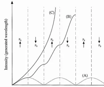
the dhection of power flow as indicated in trace (A) in figure 2.3 below. The
distance over which the relative phase of the waves changes by n is called the
t
T3
(A)
0 4/;
[image:46.616.119.457.64.345.2]Distance along crystal
Figure 2.3 The effect o f QPM on the conversion efficiency o f parametric
generation. A: nonphase-matched interaction. B: first order QPM by reversing the
sign o f Ps every coherence length Q. C: perfect phase-matching in bulk material. Q,
coherence length.
Continuous growth of the signal and idler fields requires the repeated inversion of
the relative phase between the waves after an odd number of coherence lengths.
This can be achieved by modulating the sign of the nonlinear coefficient (each
reversal termed a “domain”) which maintains the proper phase-relationship for the
growth of the generated wavelengths. The highest conversion efficiency is obtained
when the sign of the nonlinear coefficient is reversed every coherence length and is
The theory of QPM is discussed in detail by M. Fejer ® and L. Myers ^ and is
summarised below. The equations relating to QPM are similar to those of BPM with
a few simple substitutions.
For QPM the effective nonlinear coefficient is given by
dQ = [2.21]
where is the same as for the single-domain bulk material and is the Fourier
coefficient for the periodic modulation. The Fourier coefficient is given by
2
= sin(m;rD). [2.22]
m n
D = I A is the duty cycle where is the length of a reversed domain and A is
the domain period. The optimum value of duty cycle depends on the QPM order m
(Dopt=50% for m=l). The effective nonlinear coefficient for QPM is largest for a
first order process with a 50% duty cycle. In this case the nonlinear coefficient is
given by
~ ^ e f f ' [2.23]
The wave-vector mismatch for QPM is now given by
A k Q = k „ - k, - k , - k , „ > [2-24]
where is the m‘*' order grating wave-vector which is given by
k , „ ^ P ~ . [2.25]
Therefore, perfect first order QPM is achieved when
A/cq — kp — kg — ki — —^ — 0. [2.26]
For ideal periodic structures, QPM can only be achieved for m^*' orders where m is
an odd number
QPM is commonly implemented in ferroelectric crystals by periodic reversal of the
spontaneous polarisation Pg. Changing the sign of Ps, corresponding to changing the
sign of the nonlinear coefficient, is achieved by momentarily applying an electric
field using lithographically defined electrodes Such crystals are said to be
“periodically poled” with a domain (grating) period.
QPM allows longer crystals to be used and has the added advantage that the
interacting waves can be chosen to access the largest nonlinear coefficient (e.g. dgg in
any wavelength combination within the transparency range of the nonlinear material
can be phase-matched in a noncritical geometry, QPM allows phase-matching at
arbitrary temperatures with no walk-off and extends the utility of existing materials.
To date the most readily available QPM material is Periodically Poled Lithium
Niobate (PPLN) although there is an increasing interest in the new material
Periodically Poled Potassium Titanyl Phosphate (PPKTP) These poled crystals,
sometimes referred to as "chips", can be fabricated with a selection of grating periods
and novel grating designs
2.6.1 Quasi-phase-matching tolerances
In periodically poled materials the efficiency is reduced for departures from the ideal
grating structure. The effects of period and duty cycle errors on the conversion
efficiency have been analysed by Fejer et ai The point where the power
conversion efficiency is halved can be used to calculate the tolerances of these
errors.
Constant errors in the domain period, where the periodicity of the domains is
otherwise perfect, cause a shift in the phase-matching curve from the desired
operating point. This lowers the efficiency at the desired operating point. Equation
29 in ref. 8 gives the tolerance for the period to be
[2,27,
where ÔA is the period error, N = L / ml^ is the number of domains in the sample
of length L, is the coherence length. For m=l and N=1000 the tolerance for the
period is -0.2%.
Random errors in the domain period cause a broadening of the phase-matching cuiwe
due to a normal distribution of errors with standard deviation Œ/. Equation 76 in ref.
8 gives the tolerance on the mean square error to be
For N=1000 the tolerance for random period errors is -2%.
Departures from the desired domain duty cycle, usually 50/50, reduce the parametric
gain but do not affect the bandwidth. Equation 69 in ref. 8 gives the tolerance on the
rms error to be
[
2.
2,]
The tolerance for duty cycle errors is therefore -38%. Sensitivity to duty cycle
errors is very small, with rms errors as large as /^ / 3 resulting in < 50% reduction in
Equation 41 in ref. 8 gives the FWHM angular acceptance for a noncritical QPM
interaction
5v = 2 j l . 7 7 2 ^ L c o s v , [2.30]
where V is the angle of the fundamental wave vector to the z axis. Here the
bandwidth depends inversely on the square root of the device length L and is
comparable to that of a noncritical BPM interaction.
In summary, efficient QPM is very sensitive to both constant and random period
errors while being much more tolerant to errors in the duty cycle. However, with
electric-field poling (used in PPLN, PPRTA and PPKTP), where the periodicity is
precisely determined by a lithographically defined electrode, period errors have not
been a serious issue.
A nonlinear optical crystal can be placed inside an optically resonating cavity to
form an OPO, resulting in oscillation at either, or both, the signal and idler
frequencies. The nature of the oscillation is determined by the levels of feedback
provided by the cavity mirrors at the signal and idler frequencies. The optically
resonating cavity is usually external to the pump source but can also be formed
2.7 Doubly resonant oscillators
In order to reduce the pump power threshold to a level compatible with modest pump
sources and the majority of nonlinear materials, OPOs can be configured as doubly
resonant oscillators (DROs) in which both the signal and idler fields are
simultaneously resonant in the cavity
Incoming
pump © Idler
Undepleted
0
pumpSignal
Highly reflecting at signal AND idler
Figure 2.4 Doubly Resonant Oscillators (DROs) have the advantage o f very low
pump power thresholds, typically I Os of milliwatts or less. However the conditions
for the simultaneous resonance o f signal and idler are not satisfied for any arbitrary
selection o f cavity length, pump frequency, and phase matching.
2.7.1 Pump power thresholds for DROs
An important consideration in the design of OPOs is the pump power threshold
which is proportional to the product of the losses at the pump, signal, and idler
fields. The powers of the three fields are related to the number of incident photons
Pi = \aif(hVi). [2.31]
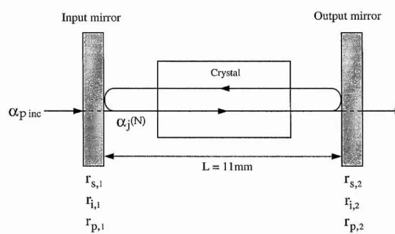
Oscillation can only occur when the round-trip gain exceeds the losses. The
threshold analysis for a linear cavity OPO, as used in the experimental configurations
detailed in this thesis, is similar to that for a ring cavity, with the exception of a
modification of the nonlinear coupling coefficient. Starting from the analysis of the
ring cavity outlined in Debuisschert et al. ^ the pump intensity required to reach
thi'eshold is given by
7T
where Yj is the transmission coefficient, y'j is defined by fj - 7j + = where
jiij is the spurious energy loss coefficient, and Ay = jg the relative detuning
FSRj
of wave from perfect resonance.
This can also be written as
\ar Uhreshold n
4|Z| F,F, 1 , [yFSR,F,-^FSR,Fj Enh„j. 1 + FSRp j , [2.34]
where Enh, - —2yp ^ is the maximum enhancement of the pump field inside the
cavity, Fj is the finesse, and FSRj is the free spectral range.
Therefore, in the case of a ring cavity DRO with pump enliancement, the pump
intensity required to reach threshold is minimum for zero detuning from exact
resonance and is given by
a K
P U r e s h o ld â \ x \ F ^ F f i n \ ' [2.35]
The discussion for the ring cavity given in ref. 5 is valid for the case of the linear
cavity provided that the coupling coefficient % is replaced by
x '
= %[l + exp(/A/:/ - [2.36]where 6 ' is the accumulated cavity round-trip phase shift for the three waves. This
is due to the fact that standing waves, and not travelling waves, must be matched for
optimum coupling in the crystal. Phase matching now depends on the mirror phase
shifts, which determine the relative position of nodes and antinodes of the three
For the case of a linear cavity DRO with pump enhancement it can be shown that the
minimum pump intensity required to reach threshold is given by ^
\a'"f = ---5-5^ --- . [2,37]
The pump power threshold can now be written in the form
P th resh old K • P - 3 8]
where K =
---Using a similar analysis for the case of a single pass pump field the pump power
threshold can be written as
[2.39]
DROs can have tlnesholds at the mW level. A major disadvantage of DROs is that
they are over constrained by requiring four conditions to be satisfied simultaneously
Energy conservation, Vs + V,. = Vp
Phase matching, ks + kf = kp
Cavity resonance for the signal field. = L
2
Cavity resonance for the idler field. Xj J.
m ~ = L 2
Table 2.2 Requirements for operation of a DRO
Therefore, operation can only occur at discrete cavity lengths where the signal and
idler frequencies satisfy the above constraints. This introduces complications in the
tuning of these devices resulting in the occurrence of mode and cluster hops
Energy consen/ation
Cavity resonance
Cavity resonance
signal freq.
idler freq.
P hase matching
[image:57.613.130.452.59.361.2]OPO oscillation
Figure 2.5 Relationship between the signal and idler resonance frequencies,
conservation of energy, and phase-matching condition on a DRO. Axes for signal
and idler modes are plotted in opposite directions. Any vertical line satisfies the
conservation of energy relation. A signal-idler mode-pair that has both resonances
centred on a vertical line satisfies the simultaneous resonance condition.
Figure 2.5. shows how the various constraints are related in a DRO. The phase-
matching condition is adequately satisfied for a range of signal and idler frequencies
and the selectivity is imposed by the requirement for simultaneous resonance of the
where and m, are the longitudinal mode numbers of the signal and idler fields
respectively, rig and U/ aie the refractive indices of the signal and idler within the
nonlinear material, Lg and L/ are the signal and idler cavity lengths, and I is the
length of the nonlinear crystal.
Small changes in either the cavity length or the pump frequency may lead to the
OPO output switching from one mode pair to another. This switch can either be to
an adjacent mode-pair (called a mode-hop) or over many mode-pairs (called a
cluster-hop)
For a fixed frequency pump source, a change in the length of the cavity by àLg j
causes a change in the resonant frequency of the signal or idler field by
Av, = ---[2.41(a)] + (^s “ 1)^
— A L; Vj-k + On -1)1
Or expressed in terms of the free spectral range FSRg f of the signal or idler cavity
AVg « , [2.42(a)]
[2.42(b)]
c
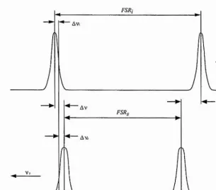
It is useful to consider the maximum detuning allowed while maintaining oscillation
on a single signal and idler mode pair. From figure 2.6 below it can be seen that tliis
maximum detuning Ay^^^ is approximately
Av„ax = Av, + Av.- < ^2 Pg + ^2 Fj , [2.43]
where AVg and Av^- are the half-width at half-maximum of the signal and idler
FSRj
AFSR
Av
FSR,
V s
Figure 2.6. Requirement for simultaneous resonance of signal and idler fields for
a DRO. The diagram shows the maximum detuning allowed if the oscillation
frequencies are to remain within the FWHM of the cavity resonances.
Eqn. (2.43) is related to the third term of the pump power threshold equation derived
in Eckardt et ai. For a DRO the pump power thieshold is
1 sine (Akll2)
^2{Av, + &v,)F,Fy^
1 +
yF,FSR, + F,FSRij [2.44]
The first term is related to the increase in the threshold for detuning from perfect
phase-matching. The second term is related to the reduction in the tlireshold when
[image:60.615.137.442.58.326.2]and corresponds to the detuning in pump frequency or cavity length that doubles the
threshold of operation for the particular mode-pair. This detuning is an indication of
the range over which the OPO can operate on a single mode-pair. Using equations
(2.42) to express the detuning as a change in cavity length, the maximum cavity
length detuning, that can be tolerated for the OPO is to remain operational on
a single mode-pair can be written as
AL^^^FSR. 1
A, + A,- < H- [2.45]
This gives the cavity length stability, AL^,„i,, required to maintain the output to a
single mode-pair to be
[2.46]
For the case of a single-cavity OPO, where it can be assumed that ALg = AL/ = AL
and F S R g « F S R j « F S R , the pump frequency stability requirement to maintain
the output to a single mode-pair is
F S R 1 1
Equating equations (2.46) and (2.47) gives the relationship between AL and Av^ to
be
AVp —• —2AL^ FSR^ [2.48]
When either pump frequency or cavity length is changed, the above equation gives
the required tuning of the other parameter in order to maintain the simultaneous
resonance of the signal and idler fields.
2.7.2 Stability requirements for single mode-pair operation of DROs
The cavity length and pump frequency stability requirements for DROs, with regard
to obtaining single mode-pair output, have been discussed by Henderson et al.
The level of cavity length or pump frequency detuning required to cause a hop to an
adjacent pair of signal and idler modes (mode-hop) is dictated by the mismatch in
the free spectral ranges, AFSR. Providing that the original mode-pair is exactly on
resonance, tuning the cavity mode frequencies by AFSR is sufficient for a mode-hop
to occur.
For an OPO in which the signal and idler fields are resonant in a single cavity, the
change in cavity lengtli required to achieve a mode-hop is given by
-'hop 2 FSR [2.50]
where X is the pump wavelength. This can also be written as
[2.51]
where n is the average refractive index for signal and idler.
Mode hop
[image:63.615.150.427.386.656.2]Mode-hops can also occur due to pump frequency detuning. The pump frequency
detuning required to cause a mode-hop is given by
= AFSR [2.52]
Mode hop
Figure 2.8. The change in pump frequency required for a mode hop. For a
change in pump frequency the frequencies of the signal and idler resonance peaks
remain fixed on the axes while the axes themselves shift relative to each other.
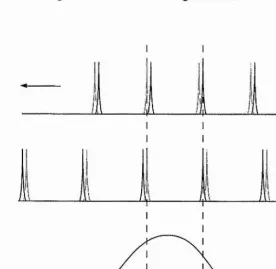
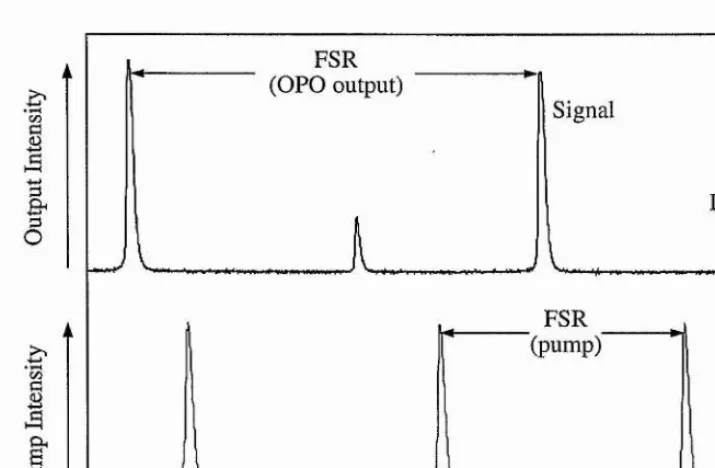
When AFSR is large, detuning the cavity length results in discrete output peaks,
corresponding to individual pairs of signal and idler modes. This discrete nature of
next adjacent mode-pair reaches threshold (see figure 2.9 below). This gives a clear
feature upon which to lock the output of the OPO and ensure single-frequency
operation. The requirement for easily stabilised operation on a single mode-pair is
therefore
^hop > AT..,'stab [2.53]
Previously Henderson et al. demonstrated single mode-pair operation of a CW-
DRO based on a bulk KTP crystal configured for near-degenerate, type-II, critical
phase-matching. Type-II phase-matching results in a large AFSR even for operation
near frequency degeneracy.
Signal frequency
Idler frequency
Signal Modes
Idler M odes
Figure 2.9 In general for type-II phase-matching near degeneracy
Scanning the cavity length results in discrete output peaks arising when particular
For type-I phase-matching near degeneracy, where AFSR is small, AL,,^,p <
Therefore, detuning of the cavity length causes hops between different pairs of
signal and idler modes while remaining above thieshold (see figure 2.10). In this
case it is more difficult to hold the output to a single mode-pair.
Idler frequency
V
Signal M odes
Signal frequency ► 1
Idler M odes
Figure 2.10 In general for type-I phase-matching near degeneracy
Scanning the cavity length causes hops between different mode-pairs while
remaining above threshold.
Chapter 8 details a DRO in wliich the signal and idler waves have the same linear
polarisation. Operation of the DRO away from frequency degeneracy was essential