A Collaborative Wireless Sensor Network Routing
Scheme for Reducing Energy Wastage
Alan W. F. Boyd, Dharini Balasubramaniam, Alan Dearle
School of Computer Science, University of St Andrews, Fife, KY16 9SX, Scotland
Email: {alanb, dharini, al}@cs.st-andrews.ac.uk
Abstract— A Wireless Sensor Network (WSN) is a network of battery-powered nodes in which data is routed from sources to sinks. Each node consumes energy in order to transmit or receive on its radio. Consequently, an intermediate node that is used by multiple sources will quickly expire. If some sources are unable to route without the presence of that node, any remaining energy they have is wasted. We present a new routing scheme known as node reliance, which rates the degree to which nodes are relied upon in routing. The use of node reliance reduces the contention for intermediate nodes, permitting sources to route to sinks for longer and thus maximising the useful lifetime of the network.
Keywords- collaborative work, energy management, routing, sensor networks
I. INTRODUCTION
AWireless Sensor Network (WSN) may be described as a network of small, autonomous, battery-powered nodes. Data is generated using sensors on source nodes and routed (possibly through multiple hops) to a sink, which typically lacks energy constraints. If sources do not coordinate their routes to sinks, it is possible that one or more nodes may be exhausted due to overuse and the network may be partitioned. When this occurs, the energy in sources that are disconnected from sinks is wasted, since they have no means to route data.
We propose a novel routing scheme known as node reliance, in which each node is weighted according to how much it is relied upon in routing. Sources then devise routes to sinks using as few highly weighted nodes as possible.
The remainder of this paper is organised as follows: Section II discusses the problem to be solved. Section III provides a review of the current WSN literature relating to the problem. The node reliance scheme is presented in Section IV. Section V shows how node reliance might be calculated using an example. Considerations for a protocol based on node reliance and consequences of a realistic physical layer are discussed in Section VI. Section VII presents the results of an experimental comparison between protocols using node reliance and other routing schemes, including load balancing. Finally, conclusions and further work are discussed in Section VIII.
II. PROBLEM STATEMENT
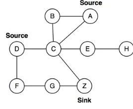
Consider the network shown in Fig. 1. It consists of nine nodes (A-H and Z) of which two nodes are sources (A and D) and one node is a sink (Z). An edge between two nodes
indicates that those nodes can communicate with each other. For convenience, we have temporarily assumed that communication is bidirectional.
[image:1.595.363.497.312.422.2]Within the network, it is obvious that certain nodes are more important to maintaining (source, sink) connectivity than others. For example, the loss of sink Z renders the network useless. The loss of node C makes source A useless, but allows source D to continue operating. Finally, the loss of node E or H has no effect.
Fig. 1: An example network containing two sources and one sink
In a non-collaborative routing scheme, each source determines the optimal path for routing to a sink. For example, the optimal routes to the sink might be ACZ from source A and DCZ from source D. However, both of these routes require the use of node C, a node that is essential for the operation of source A.
A collaborative scheme may require source D to use the non-optimal route DFGZ, thus reducing the energy expenditure of node C. Our scheme is collaborative in that sources determine routes based on a holistic view of the network avoiding the use of nodes upon which others rely.
III. RELATED WORK
A. Minimum hop routing
Minimum hop routing selects a path based on the minimum number of hops necessary to reach a sink. The oldest minimum hop routing protocol is DSDV [1], later superseded by AODV [2] which forms routes on demand rather than proactively. Both protocols operate similarly. A route request (RREQ) message, containing a sequence number, the source from which the message originated and the number of nodes through which the message has travelled, is flooded through the network. Eventually, some node that has a path to the destination or is the destination receives the message, and that node responds with a route reply (RREP), which is routed back through the network. Each node forwards the RREP to the node from which it received the original RREQ. Since each RREP message is required to travel the same path as the corresponding RREQ, but in the reverse, AODV and DSDV both require bidirectional edges.
In DSR [3], all RREQ messages contain the sequence of nodes through which they have travelled. The RREP is encapsulated in its own RREQ so that a path can be discovered from the sink back to the source, and contains the sequence of nodes from the RREQ originating from the source. Since the RREP is flooded, there is no requirement for edges to be bidirectional. Therefore, route discovery requires two floods per (source, sink) pair. RREQs and RREPs must also carry a sequence of node identities rather than a simple hop count. These two features combine to limit the scalability of protocols such as DSR.
In [4-7] it has been suggested that minimum hop routing is prone to a number of disadvantages. Firstly, minimising the number of hops encouraged the use of nodes that are geographically distant [4]. Since energy expenditure is argued to be proportional to either the second [5] or fourth power [8] of the distance, long hops either require more energy or are less reliable for a fixed amount of energy. Secondly, it has been suggested that the use of minimum hop routing (and more generally shortest path routing of which minimal hop is an example) causes a subset of nodes to expire more quickly [6, 7], potentially disconnecting sources from sinks. For example, in Fig. 1, the use of the minimum hop routes from A and D (ACZ and DCZ) would cause C to expire quickly, and disconnect A from Z.
B. Minimum energy routing
Since there is a polynomial relationship between the energy required for transmission and the transmission distance, a longer sequence of small hops may require less energy than a short sequence of long hops. Minimum energy routing seeks to use (source, sink) paths of least energy expenditure.
In MLRP [9], when an RREQ message is sent from a source, it specifies a minimum transmission power that must be used. Any node receiving an RREQ retransmits it at the power specified in the message. After some period of time, if the source has not received an RREP, it increases the transmission energy and resends the RREQ. The protocol
therefore returns the minimum hop path of least energy. Although MLRP assumes bidirectionality, the proposal of using an incremental transmission power can be applied to virtually any other routing protocol. However, MLRP encourages the global use of nodes with low transmission energies. For example, if the transmission cost of C to Z in Fig. 1 is small then the use of node C is encouraged, even though its loss would disconnect source A. It could be argued that since C’s transmission power is low, it will take much longer to expire. However node C may only be fractionally cheaper than some alternative. Furthermore if every source routes through node C, it may still expire very quickly.
C. Load balancing routing
Load balancing routing distributes the routing workload across as many nodes as possible, even if the paths chosen by sources are not optimal with respect to the energy consumption.
The MREP [10] (also known as Max-min) routing protocol works by selecting the path whose node of least remaining energy is the greatest (the maximum minimum element). In MREP, the cost of a node is inversely proportional to the remaining energy of that node and the lowest lexicographically ordered path is used. Lexicographically comparing two paths P and Q involves an examination of the highest cost node on each path. The path whose highest cost node has the lowest cost has the lowest lexicographic order. If the nodes are of equal cost, the next highest cost nodes are examined, and so on.
Load balancing routing suffers from two disadvantages. Firstly, it is difficult to determine the remaining energy on each node. Secondly, distributing the routing workload might cause additional energy expenditure.
In order to provide an accurate approximation to the amount of energy stored in a node, Lin [11] proposes representing the energy of nodes using discrete energy levels. Using this technique, a four-level logarithmic scale is proposed with level 0 corresponding to full energy, level 1 between half and full energy, level 2 between quarter and half energy, and level 3 between one eighth and zero energy. Whilst this reduces the overhead associated with load balancing, routes are required to be recalculated when any node changes its energy level.
Load balancing typically puts off the time until first node expiration by distributing workload. However, this approach does not necessarily reduce the wastage of energy of sources since it may be to the detriment of the entire network’s energy.
D. Potential based routing
are lowered. Adjusting the scores in this manner ensures that other routes to the sink are not disrupted and allows new paths to be formed using only a subset of local nodes. Unlike our proposed routing scheme, PMRP does not actively encourage lifetime extension or the preservation of particular nodes.
IV. NODE RELIANCE
None of the routing schemes examined in Section III are suitable for minimising the energy wastage of source nodes. We therefore introduce a new means of costing nodes known as node reliance and demonstrate how it may be applied to form routes that minimise energy wastage at sources.
The premise of node reliance routing is that each node is assigned a weighting, which gives an indication of how much that node is relied upon in routing from sources to sinks. A node that is greatly relied upon should be avoided where possible, whereas a node that is not relied upon can be used freely. Each source may rely on a particular node to a different degree. Any model of node reliance must be able to distinguish between how relied upon a node is to a particular source and in the context of the entire network. To distinguish between these concepts, we make the following definitions:
• The relative reliance of a node B to a (source, sink)
pair (A, Z) is the degree to which node B is relied upon in routing data from A to Z.
• The absolute reliance of a node B is the degree to
which node B is relied upon in the entire network. Several models may be used to express node reliance. In this paper, we present the simplest paths model. A simplest path is a sequence of nodes from a source to a sink such that it is not possible to construct another path between the same (source, sink) pair by removing nodes. For example, in Fig. 1, the pair (A, Z) has one simplest path: ACZ and (D, Z) has two: DCZ and DFGZ. The path ABCZ is not a simplest path, because it is possible to remove node B to form the path ACZ. Our model considers the set of simplest paths between each (source, sink) pair. A given (source, sink) pair may have multiple simplest paths associated with it. In the simplest paths model, a path may never contain more than one sink. Consequently, the set of paths under consideration is actually the set of single-sink, simplest paths.
The relative reliance, of a node B to a (source, sink) pair (A, Z) is the proportion of simplest paths between A and Z on which node B lies. If node B is a bottleneck, then it lies on all paths between A and Z and its relative reliance is 1. If node B does not lie on any simplest paths, then it is unused in routing, and it has a relative node reliance of 0. The absolute reliance of a node under this model is the average of relative reliance across all pairs for which there is at least one path. The set of simplest paths is considered in calculating node reliance since it contains all routes from a source to a sink that have no superfluous nodes. The loss of such nodes does not prevent sources from routing to sinks.
Once reliance values have been assigned to nodes, it is
necessary to determine the cost of each available path in order to establish the optimal one. The results (Section VII) indicate that shortest path routing maximises (source, sink) connectivity. Thus, the optimal path is the one where the sum of reliance costs of nodes is the least.
As discussed in Section III, shortest path routing causes a subset of nodes in the network to be overused and quickly disconnected from the network. However, these concerns do not apply when node reliance is used, since the cost of a node is inversely proportional to the number of paths on which it lies. Consequently, it is unlikely that the cheapest nodes can be overused. Even if overused, they will be of little importance in routing by definition.
V. EXAMPLE
To illustrate the approach, we use the network shown in Fig. 1. The pair (A, Z) has one simplest path (ACZ). Consequently, all three nodes, A, C and Z have a relative reliance of 1.0 to the pair (A, Z). The pair (D, Z) has two simplest paths (DCZ and DFGZ). Thus, nodes C, F and G each have a relative reliance of 0.5 to the pair (D, Z) and D and Z have a relative reliance of 1.0 to (D, Z). Nodes that do not lie on any simplest path between a (source, sink) pair have a relative reliance of 0. A node’s absolute reliance is equal to the mean of its relative reliances. For example, node D has a relative reliance of 0 to (A, Z) and a relative reliance of 1 to (D, Z), giving it an absolute reliance of 0.5. The reliance values for the nodes shown in Fig. 1 are shown in Table I.
Visual inspection reveals the absolute and relative reliance values follow intuition. The most valuable node is sink Z whose loss would cause the entire network to fail (if the network had multiple sinks, then this value would be lower). The next highest reliance value node is C. Node C is a bottleneck to source A and therefore if C were to expire, A would be disconnected from the network. Furthermore, the loss of node C causes half D’s (source, sink) paths to become unusable. Thus, node C is given a high absolute value. The loss of a source node yields that node unusable and consequently the source nodes have the next highest reliance value. Although not relevant in this network, where no simplest path contains both sources, it is important to consider the reliance values of sources, since it may be beneficial to the
TABLE I
RELATIVE AND ABSOLUTE NODE RELIANCE VALUES
Node
Relative reliance to
(A, Z)
Relative reliance to
(D, Z)
Absolute reliance
A 1.00 0.00 0.50
B 0.00 0.00 0.00
C 1.00 0.50 0.75
D 0.00 1.00 0.50
E 0.00 0.00 0.00
F 0.00 0.50 0.25
G 0.00 0.50 0.25
H 0.00 0.00 0.00
entire network for one source to route through another. Of the remaining nodes, F and G have a low reliance because they are unused by source A and appear on only half the simplest paths of source D. Finally, nodes B, E and H are all unused. There is no simplest path from any source to any sink that uses any of these nodes. Thus, their reliance value is 0 and their loss has no impact on (source, sink) connectivity.
In general, having assigned reliance values to nodes, it is possible to determine which path is the cheapest for each source. It is only necessary to consider the set of simplest paths; any non-simplest path contains nodes that are unnecessary, and thus, a path of lower cost must exist.
The only simplest path from source A to sink Z is ACZ. Its cost is calculated by adding the node reliance values of A, C and Z to give a total of 2.25 (0.50 + 0.75 + 1.00). There are two paths from source D to Z, DFGZ and DCZ. The cost of DFGZ is the sum of the costs of D, F, G and Z, which gives 2.00 (0.50 + 0.25 + 0.25 + 1.00). The cost of DCZ is the sum of the costs of D, C and Z, which gives 2.25 (0.50 + 0.75 + 1.00). Thus, the optimal routes are ACZ and DFGZ. Assuming the sink has a sufficient energy to receive every message generated at the source nodes and assuming that every message sent from sources to sinks consumes the same amount of energy on each node then both sources will expire simultaneously and no energy will be wasted at any source.
VI. DISCUSSION
In this section we discuss node reliance and its implications for routing protocols. We also examine the significance of realistic physical layers in which communications may be unreliable and alternatives to the simplest paths model.
A. Node reliance routing protocol
This paper has described a new routing scheme. We now consider how this scheme may be converted into a routing protocol. The node reliance routing scheme only requires knowledge of the network topology. However, since the full set of paths between all sources and sinks in the network must be known, it is necessary to have a view of the entire network. Preliminary experiments have indicated that the most suitable means of gathering the network topology is by link state advertisement (LSA), i.e. each node shares its set of neighbours with all other nodes in the network. The growth rate of such an operation is O(n2) where n represents the number of nodes in the network.
Although this growth rate is high, the use of LSA has a number of advantages. Firstly, the cost of LSA does not increase as a result of increasing the proportion of sources since each node has a view of the network. Secondly, non-LSA routing protocols often deal poorly with unidirectional links. A common tactic is to assume that every edge is bidirectional. However, this may result in the selection of an unusable path, causing the routing protocol to fail. Another solution is to carry out forward and backward path discovery in the same way as DSR (discussed in Section III.A). Such a
process involves one flood per source to find paths to the sink(s) and one flood per sink to discover path to the source(s). Furthermore, each message must contain a partially constructed path to the destination and similarly the RREP message must additionally contain the (source, sink) path. However, it may be argued that any routing protocol that can exploit unidirectional links has lower efficacy than one that assumes bidirectionality.
B. Realistic physical layer
In a physical WSN deployment, it may be difficult to define when two nodes are connected. In reality, a node B receives a transmission from a node A based on some probability P which is dependent upon the distance between A and B, the power with which the transmission is sent, the sensitivity of the receiver and the local noise which includes other radio transmissions. The probability of radio reception may also be dependent on factors that change over time. For example, poor weather or obstacles moving between the nodes may cause the reception probability to drop. To address the problem of deciding when two nodes are connected, Stojmenovic [13] provides a number of potential solutions. The simplest of these is for each node to make a number of attempts to communicate with potential neighbours. The nodes that are reliably discovered some proportion of times are considered to be directly connected. It is possible that some nodes capable of receiving transmissions may not be included in this list. However, those nodes are unlikely to be reliable and so it may be argued that it is undesirable to use them.
C. Alternative node reliance models
Sometimes the use of a node is predetermined by some earlier routing decision. For example, in Fig. 1, the use of node F always requires use of node G, which has no impact on the path selection or the attribution of node reliance values. Where the use of such nodes is deterministic, it is possible to contract the network such that the two nodes are combined into a single virtual supernode. It is hypothesised that by considering this smaller set of nodes, the accuracy of node reliance values may be improved.
A final consideration is in message overhearing. Since radios do not usually have the ability to unicast, a node may expend energy receiving a message and decoding it before determining that it was not the intended recipient. Taking overhearing into account when calculating a node’s reliance value may improve the accuracy of node reliance values appreciably and further reduce the energy wasted by sources.
expenditure used as a consequence of overhearing.
VII. RESULTS
The Castalia 1.3 simulator was used to compare the efficacy of the node reliance routing scheme with other well-known protocols. Networks of 2, 5, 10, 20 and 40 nodes were placed in triangular, square, hexagonal and random shaped deployments. For each network, sources and sinks were randomly selected and each experiment was repeated 30 times using different random seeds and different sources and sinks. The simulated application caused each source to generate a randomly sized piece of data (between 2 and 100 bytes) every five seconds and route it to a sink. For each routing protocol, the normalised total data transfer and connectivity weighted transfer (CWT) [14] were calculated. CWT is the product of transferred data and the number of different sources that provided the data, raised to some power (2 in these experiments). It therefore represents the degree to which sources remain connected to sinks and is thus representative of well-spent energy.
TABLE II
COMPARISON OF ROUTING PROTOCOLS
Heuristic Gathering Topology Ordering CWT Transfer
Load
Balance [8] LSA Shortest 0.988±0.000 0.983±0.000
Contracted LSA Shortest 0.985±0.000 0.986±0.000
Simplest LSA Shortest 0.984±0.000 0.985±0.000
Min Hop LSA Shortest 0.972±0.000 0.983±0.000
Load
Balance [8] DSR Shortest 0.961±0.000 0.961±0.000
Contracted LSA Lexicographic 0.956±0.001 0.972±0.001
Simplest LSA Lexicographic 0.954±0.001 0.971±0.001
The results show that load balancing is slightly better than the node reliance approach described here (with a very small margin). The node reliance approach achieves higher transfer again, with a small margin.
We postulate that with the addition of the overhearing compensation, reflecting real–world conditions, described in Section VI.C, that this protocol may prove to be superior.
VIII. CONCLUSIONS AND FURTHER WORK
This paper has examined mechanisms for reducing the wastage of energy on source nodes in a WSN when routing data from sources to sinks. Common routing protocol approaches such as minimum hop routing, minimum energy routing and load balancing routing were argued to be problematic and may not be capable of resolving the problem.
A new collaborative routing scheme known as node reliance was introduced. Rather than having each source dynamically negotiate which path to use, node reliance assigns a score to each node based on the degree for which it is relied
upon for routing. By firstly using those nodes that are least relied upon, it is theorised that sources will naturally choose paths that either have minimal conflict or whose expiration has the least effect on the network.
Possible further work includes merging features from other routing protocols. For example, by additionally considering load balancing, a routing protocol could encourage the use of nodes with low reliance or with high remaining energy. One might also consider combining node reliance with a clustering protocol such as LEACH [5]. Since clusters are independent, node reliance values for a cluster would only require the topology of that cluster rather than the entire network. Thus, the scalability of the routing protocol could be improved.
Finally, we intend to evaluate the reliance model discussed in Section VI.C, in which message overhearing is taken into account when calculating a node’s reliance value.
REFERENCES
[1] C. E. Perkins and P. Bhagwat, "Highly Dynamic Destination-Sequenced Distance-Vector Routing (DSDV) for Mobile Computers," ACM SIGCOMM Computer Communication Review, vol. 24, pp. 234-244, 1994. [2] C. E. Perkins and E. M. Royer, "Ad-hoc On-Demand Distance Vector Routing," in Proceedings of the Second IEEE Workshop on Mobile Computer Systems and Applications, New Orleans, USA, 1999, pp. 90-100. [3] D. B. Johnson, et al., "DSR: The Dynamic Source Routing Protocol for Multi-Hop Wireless Ad Hoc Networks," in Ad-Hoc Networking, C. E. Perkins, Ed., ed: Addison-Wesley, 2000, pp. 139-172.
[4] A. Woo, et al., "Taming the Underlying Challenges of Reliable Multihop Routing in Sensor Networks," in Los Angeles, California, USA, Conference On Embedded Networked Sensor Systems, 2003, pp. 14-27. [5] W. R. Heinzelman, et al., "Energy-Efficient Communication Protocol for Wireless Microsensor Networks," in 33rd International Conference on System Sciences, Hawaii, USA, 2000, pp. 8020-8029. [6] H. Dai and R. Han, "A Node-Centric Load Balancing Algorithm for Wireless Sensor Networks," in IEEE GLOBECOM - Wireless Communications, San Francisco, USA, 2003, pp. 548 - 552.
[7] S. Singh, et al., "Power-Aware Routing in Mobile Ad Hoc Networks," in Mobile Computing and Networking, Dallas, Texas, United States, 1998, pp. 181-190.
[8] G. J. Pottie and W. J. Kaiser, "Wireless Integrated Network Sensors," Communications of the ACM, vol. 43, pp. 51-58, 2000.
[9] B. Zhang and H. T. Mouftah, "Energy-aware on-demand routing protocols for wireless ad hoc networks," Wireless Networks, vol. 12, pp. 481-494, 2006.
[10] J.-H. Chang and L. Tassiulas, "Routing for Maximum System Lifetime in Wireless Ad-hoc Networks," in 37th Annual Allerton Conference on Communication, Control and Computing, Monticello, IL, 1999.
[11] L. Lin, et al., "Asymptotically Optimal Power-Aware Routing for Multihop Wireless Networks with Renewable Energy Sources," in 24th Joint Annual Conference of the IEEE Computer and Communications Societies, Miami, FL, USA, 2005, pp. 1262 - 1272.
[12] D. Y. Kwon, et al., "A Potential Based Routing Protocol for Mobile Ad Hoc Networks," presented at the 11th IEEE International Conference on High Performance Computing and Communications, Seoul, Korea, 2009.
[13] I. Stojmenovic, et al., "Design Guidelines for Routing Protocols in Ad Hoc and Sensor Networks with a Realistic Physical Layer," IEEE Communications Magazine (Ad Hoc and Sensor Networks Series), vol. 43, pp. 101-106, 2005.