RESEARCH ARTICLE
POWER FLOW CONTROL IN THE GRID USING CONTROLLABLE NETWORK TRANSFORMER –
A SMART DEVICE TO IMPROVE THE SYSTEM RELIABILITY
[
Gayathri, G*1., Neena Ramesh2 and Sharmeela, C3
*1,2SRM Easwari Engineering College, Chennai, Tamilnadu, India
3Anna University, Chennai, Tamilnadu, India
ARTICLE INFO ABSTRACT
The increasing load growth, decreasing investments and increasing penetration of dyanamic sources and loads have severely increased the stress on the electric grid. This growing stress has forced operators and regulators to think of delivering energy in a smart, controllable and reliable way to the customers. Tie-lines connecting two systems are one of the traditional methods used by utilities to improve the system reliability. However, often specially during contingencies, tie-lines get overloaded due to the lack of power flow controllability through them. Controllable Networ k Tra nsf or mers (CNTs) ar e smar t assets which can be realized by augmenting existing Load Tap Changing (LTC) transformers in order to achieve power flow control. This paper proposes the design of CNT, their implementation and analysis of their performance in tie-lines to make them smart and controllable, without compromising the system reliability.
INTRODUCTION
The increased load demand, increasing penetration of highly stochastic renewable energy and limited transmission investments has significantly increased the stress level on the grid. The energy outlook of the customers has also changed significantly over time, thereby creating an increased demand for better quality, high reliability and environmentally friendly energy. The slow electromechanically controlled grid of the previous century needs to be revamped drastically in order to make it capable of fulfilling the new objectives of the energy delivery system. The present grid needs to be transformed in a cost effective way into a smart and controllable grid which is fast, adaptive, self-healing, efficient and reliable.
Historically most of the power systems were radial, but the need for higher reliability levels made the utilities shift to a more meshed system. . One common method of increasing the system reliability that is often adopted by utilities is the use of tie-lines for connecting two systems. The tie-lines provide a path for power flow from high generation areas to low generation areas. Tie-lines are also often added between two networks of different voltage levels, in order to provide a redundant path for power flow, in case of outage of one of the networks. However, in a highly meshed network, operators have little or virtually no control over the path of the power flow. For a given state of the system, the laws of physics determine the power exchange occurring through each of the tie-lines, while the net power transfer between the two areas is noted for billing purpose. The tie-lines are often not required to carry much power during normal operation, their main purpose being to transfer power from one area to another during system contingencies.
*Corresponding author: [email protected]
However, due to the lack of controllability of power, often tie-lines get overloaded during contingencies causing them to trip, thus further aggravating the power shortage problem in the contingency affected area. The shunt VAR compensators and the LTC transformers help in regulating the bus voltages. Phase Shifting Transformers (PST) can provide some level of slow, non-adaptive control over line power flow (Sen and Sen, 2003). However, the inter-phase connections lead to complex fault modes. The Flexible AC Transmission Systems (FACTS) devices received much attention for the past two decades and a number of these FACTS devices have varying levels of power flow capability. Although the FACTS technology has reached a stage of technical maturity, yet they failed to achieve significant market penetration.
The Unified Power Flow Controller (UPFC) injects voltage compensation in series and current compensation in shunt in order to control both the line current as well as the bus voltage
(Edris et al., 1998). Back-To-Back (BTB) HVDC link can also
be used to connect two systems, which uses two bi-directional voltage source converters to exchange power through a
common dc link (Bagen et al., 2007). The Variable
Frequency Transformer (VFT) is another alternative of connecting two areas. It uses a slow rotating transformer to exchange power between the two systems. Unlike the BTB and the UPFC which uses power electronic switches, the VFT is an electro-mechanical device with response times in the order of 1-2 seconds (Marczewski, 2007; Divan and Sastry, 2008). Although technologies like UPFC, BTB and VFT are capable of power flow control, their implementation at sub- transmission or transmission level is extremely complex and
expensive. Besides these technologies require high
maintenance and reduce the system reliability. This paper proposes augmentation of an existing load tap changing
ISSN:
0975-833X
International Journal of Current Research
Vol. 33, Issue, 4, pp.245-249, April, 2011
INTERNATIONAL JOURNAL OF CURRENT RESEARCH
Article History:
Received 11th
January, 2011 Received in revised form
24th
February, 2011
Accepted 15th
March, 2011
Published online 27th
April 2011
Key word: Increasing load growth Decreasing investments Increasing penetration Dyanamic sources
transformer to provide dynamic vernier control of voltage magnitude and phase angle simultaneously over a meaningful control range. The Controllable Network Transformer (CNT) proposed is a “smart asset” that provides control of bus voltages and line currents in a meshed system; this is not achievable using conventional techniques. The converter used can be described as a Thin AC Converter, or TACC. The use of the so- called Dual Virtual Quadrature Source (DVQS) technique allows the CNT to control both the line current as well as the bus voltage, enabling it to achieve vernier control
over the power flow in a meshed network (Noroozian et al.,
1998).
II. THIN AC CONVERTER – BASIC CONCEPT
[image:2.612.331.549.127.265.2]The underlying motive is to achieve dynamic grid control while increasing the economic efficiency at the system level through the utilization of existing utility assets. Desired dynamic control of the asset is realized using a ‘thin ac converter’ that consists primarily of power semiconductors and high-frequency filter elements with minimal energy storage, and which is located between the grid and the asset (Figure 1). The Thin AC Converter or TACC would primarily provide power conversion, but would use the asset itself for all low- frequency energy storage functions, realizing significant reduction in size and cost.
Fig. 1. Concept of a Thin AC Converter
The voltage and power ratings for such TACCs would vary, depending on whether the device is to be used in a For controlling the phase of the output voltage, the technique of Dual Virtual Quadrature Sources (DVQS) is applied (Noroozian
et al., 1998). Figure 3a shows a simple ac chopper circuit. Using conventional PWM techniques, an output voltage of the same phase but lesser magnitude, as shown in Figure 3b, can be obtained. However it is not possible to produce an output voltage with a different phase and/or harmonic content, as shown in Figure 3c, using standard PWM techniques. Important voltage ranges are 4 kV to 161 kV for distribution, and 230 kV – 760kV for transmission. This raises significant challenges today, particularly for the transmission end of the application spectrum. However, the emergence of applications such as HVDC Lite from ABB suggests that these applications may also prove to be viable.
III. CNT BASICS
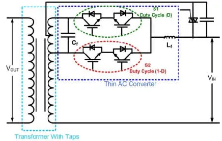
The CNT is capable of providing simultaneous control over bus voltage magnitude and phase. Figure 2 shows the schematic of the CNT. An existing LTC is augmented by a direct bi-directional ac-ac converter. The converter consists of two ac
switches, a small filter capacitor and inductor. The main advantage of this topology is that the converter can be rated at only a fraction of the transformer rating as the switches have to handle only a fraction of the transformer rated voltage. The technology is scalable to sub-transmission and transmission level using multi-level ac-ac converters.
Fig. 2. Controllable Network Transformer
Assume that the two switches S1 and S2 are operated at fixed duty ratios D and (1-D). When the switch S1 is on, the turns ratio of the transformer is 1 :( 1+n), while when the switch S2 is on it becomes 1 :( 1-n). By applying a fixed duty ratio D, it is possible to achieve the de sired output voltage magnitude. However, by u s i n g standard PWM techniques it is not possible to control the phase of the output voltage. This is because there are no storage elements in the circuit which can provide energy during the zero-crossings of the input voltage. The output voltage angle in this case is thus the same as that of the input voltage. For controlling the phase of the output voltage, the technique of Dual Virtual Quadrature
Sources (DVQS) is applied (Noroozian et al., 1998). Fig. 3a
shows a simple ac chopper circuit. Using conventional PWM techniques, an output voltage of the same phase but lesser magnitude, as shown in Figure 3b, can be obtained. However it is not possible to produce an output voltage with a different phase and/or harmonic content, as shown in Figure 3c, using standard PWM techniques. The output voltage obtained by the DVQS technique can be divided into three components. The first component is the output voltage which is in phase with the input voltage (Vd0). Additionally two other virtual sources are invoked in quadrature to the input voltage. One of these sources is at fundamental frequency (Vq0) while the other one is at the third harmonic frequency (V3). The sum of all the three components must at all instances of time lie within the envelope of the input voltage. Figure 4a shows the different components of the output voltage along with the input voltage. The output obtained at the fundamental frequency is the sum of the components Vd0 and Vq0, which can now be phase shifted from the input voltage as shown in Figure 3.
Figure 3: AC choper (a) Circuit topology, (b) Achievable output voltage, (c) Unachievable output
[image:2.612.54.299.344.481.2]Figure 4: (a) Various components of the output voltage obtained using DVQS strategy, (b) Input and phase
shifted output voltage.
IV. CNT ANALYSIS, MODEL DERIVATION AND SIMULATION
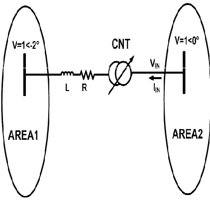
In this section, the analytical model of the CNT is derived. It is assumed that the CNT is placed on a tie-line connected between two control areas—area1 and area2, as shown in Fig. 5. The two areas may be connected to each other by more than one tie- lines. Assume the buses to which the CNT is connected are bus J and bus K. The voltages at these two buses are assumed to be separated by a phase difference of δ◦ . The sum of inductance of the transmission line and the transformer reflected to the area1 side is assumed to be L. For the purpose of this analysis, the losses in the transmission line and the CNT are neglected. The DVQS is implemented using the EHM scheme. The scheme can be implemented using sine-triangle PWM scheme, with the control reference voltage consisting of a dc component K0 , a second harmonic of amplitude K2 , and a phase angle Φ. The duty cycle of the switch S1 is given by (1). The voltages at the two buses are given by (2) and (3), respectively. The voltage at the output of the CNTVO can be expressed in terms of the input voltage VIN , duty cycle D, and the tap ratio n, as shown in (2).
D = K0 + K2 sin (2ωt + Φ) (1)
It is, thus, seen that the CNT provides a wide control range in terms of both real and reactive power. The converter for the
aforementioned CNT should be rated 20% of the transformer rating, which comes to about 90 MVA. The control area, can be increased by increasing the value of the off- nominal tap ratio n. However, increasing n also increases the rating of the converter. The implementation of the converter for the CNT
will likely use multilevel ac converters (Noroozian et al.,
[image:3.612.91.270.60.399.2]1998). It is possible to reduce the number of levels by introducing a step- down transformer, but it will introduce an additional expense. Availability of new device technologies such as SiC gate turn- off devices rated at 10–20 kV may make the implementation of this technology simpler at these voltage levels.
Fig. 5. CNT on a tie line connecting two control areas
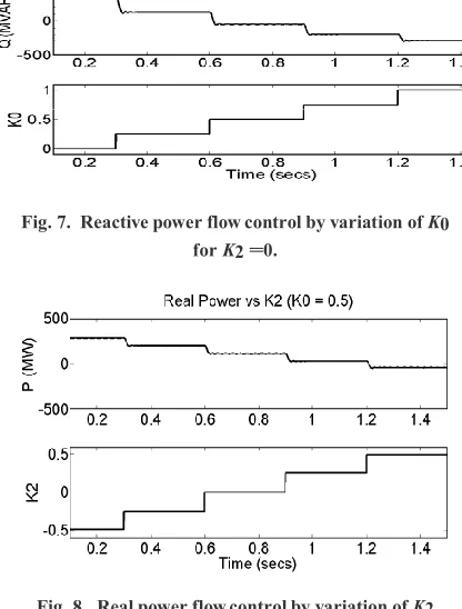
The system presented in the previous section is simulated using the Simulink and MATLAB. The schematic of the simulated system is shown in Fig 6. In order to simulate a stable system, sufficient resistance is introduced in the system. The X/R ratio of the line was assumed to be 10. Fig. 7 and Fig. 8 shows the reactive power and real power flowing through the line, as the K0 is varied from 0 to 1 in steps of 0.25, while the K2 is kept at 0. The results obtained in the simulation show that the reactive power flow at the sending end of the line can
[image:3.612.332.556.191.346.2]be varied from −300 to 350 Mvar.
[image:3.612.334.545.491.694.2]Fig. 7. Reactive power flow control by variation of K0
for K2 =0.
Fig. 8. Real power flow control by variation of K2
for K0 = 0.5.
V. COMPARISON WITH AVAILABLE TECHNOLOGIES
In this section, the CNT is compared to the existing power flow control technologies in terms of cost and functionality. Utilities sometimes use BTB HVdc links and VFT to transfer power between two areas. The BTB link is implemented with two BTB thyristor converters to realize a “local” HVdc system. The VFT uses a rotating transformer to allow interconnection between two systems at different frequencies or phase angles. The PST creates a shift in phase by adding components of other phases. One of the major advantages of the CNT over most other power flow controllers is the independence of the phases. All the three phases are connected to the common dc link in the case of BTB. The PST has interconnection between all the three phases. As a result, a fault or disturbance in one phase gets reflected to all three phases. Since most of the power system disturbances are single phase, it can increase the observed disturbances in a phase almost twice. As a result of this interphase interaction, setting protective relays become challenging. Both the BTB link and the VFT require two transformers for stepping down from the line voltage. These transformers are required to carry the rated power. The VFT is essentially a rotating transformer, which has to handle the entire power. For implementation purposes, often 8–10 VFTs are operated in parallel in order to share the load. The CNT on the other hand requires only one transformer, which has to handle the rated power. This can even be an existing LTC, which can reduce the installation cost significantly. The converter of the BTB link is also required to handle the full-rated power. The CNT converter on the other hand is only fractionally rated, compared to the transformer rating. The converter of the CNT used for analysis of the system in Fig. 5, is rated at 20% of the transformer rating. From functionality
point of view, both BTB and VFT can provide full control over the power through the line. They also have the capability of connecting two asynchronous systems. Like the BTB and the VFT, the CNT can vary the line power smoothly in both directions. In some situations the CNT can even reverse the direction of the power flow. As can be seen from Fig. 6, the degree of control achieved by the CNT is also very high, and although the controllability is not as wide as BTB or VFT, in most practical situations it may be enough for system operators to fulfill their objectives. Conventional power flow controllers like the BTB and the VFT being expensive and complex are looked upon as central power flow controllers. On the other hand, since the CNT can be realized by augmenting existing network LTC, it is relatively inexpensive and simple. As a result, it can be viewed as a dis- tribute solution to the network power flow control problem. As a result, in a meshed network with multiple CNTs, the operators are expected to have significantly more flexibility than a net- work with just one or two central point power flow controllers. The distributed nature of the CNT also makes it a more reliable technology, as the loss of one or two devices would not impact the system operation by a huge margin. Loss of a central large- scale power flow controller like a BTB or VFT can negatively impact the network operation by a significant margin.
One of the biggest advantages of the CNT is its “fail normal” mode of operation (Divan and Sastry, 2007). In case of a converter failure, a CNT can be restored back to a normal transformer by the bypass semiconductor switches. Hence, even in case of failure of a converter, the line reliability is restored back to its “normal” state. In case of most other power flow controllers, the failure of a converter forces the line to trip, which reduces the overall system reliability and can even result in cascading failures.
EXPERIMENTAL RESULTS
In order to validate the CNT operation, a prototype CNT rated at 480 V, 2 kVA was built at the Intelligent Power Infras- tructure Consortium (IPIC) laboratory at Georgia Institute of Technology. The CNT was realized using a standard 480/240 V center-tapped transformer, as shown by the schematic in Fig. 9. The output of the CNT is looped back to its input through a resistance and an inductance.
Fig.9.Schematic diagram of the experimental setup
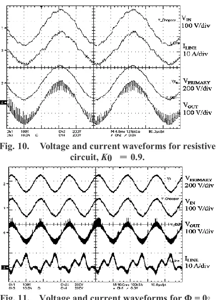
[image:4.612.333.551.537.680.2]flow in the line as it is connected to exactly same voltage at each end. However, with the CNT, both the power flow magnitude as well as the direction can be controlled. From the schematic, it is clear that the CNT effectively has an off-nominal tap ratio of 25% (n = 0.25). The two-level thin ac converter realizes two ac switches using four insulated gate bipolar transistors rated at 100 A, 1200 V switching at 10 kHz. Initially, the CNT is operated using conventional PWM techniques. Thus, the gating signal is assumed to have only a dc component with K0 = 0.9. The circuit is kept mostly resistive with R = 3.5 Ω, while external inductance is kept at zero. The voltage and current waveforms obtained by this method is shown in Fig. 10.
Fig. 10. Voltage and current waveforms for resistive circuit, K0 = 0.9.
Fig. 11. Voltage and current waveforms for Φ = 0◦ .
[image:5.612.78.281.605.721.2]input voltage of about 155 V, the power flowing in the circuit is 1.3 kW. The CNT is operated at two more operating points. In both the cases, the values of K0 and K2 are kept constant at 0.5 and 0.2, respectively, while the value of Φ is varied. The circuit for these two operating points is made inductive. Fig. 11 shows the voltage and currents for Φ= 0◦ , while Fig. 12 shows that for Φ = 180◦ .It is observed that for an input voltage of 80 V, the CNT can push as much as 260 W of power for Φ = 0◦ . For Φ = 180◦
Fig. 12. Voltage and current waveforms for Φ = 180◦
the direction of power flow is reversed and −360 W of power flows through the circuit. The reversal of the current phase can be easily seen, comparing Figs. 10 and 11. At K0 = 0.5 and K2 = 0, the current in the circuit should be zero. Hence, the control effort required in the form of second harmonic injection is maximum at this point. As a result, the current is observed to have significant level of third harmonic. It is possible to reduce the harmonic content in the line current using third harmonic traps. Also in many utility situations, it might be possible to control the power flow to a desired level, using limited amount of harmonic injection. A 4 kV, 200 kVA prototype CNT is presently being built at the IPIC laboratory.
CONCLUSION
Tie-lines are created between two areas to increase the re- liability of the overall network. However, improper control of tie-line power can lead to high network stress or even catas- trophic failures. Need for power flow control through tie-lines is expected to grow significantly in near future, as policies like Renewable Portfolio Standard and carbon mandates may force many states to import power from renewable rich areas. This paper shows that the CNT can be a simple and cost- effective device capable of achieving smooth and bidirectional power flow controller. The CNT can potentially become one of the alternatives to control the power especially through tie- lines connecting two control areas. The technology is scalable to medium voltage levels using available silicon devices. The paper develops an analytical expression for the operation of the CNT. Simulation results showing the control capabilities of the CNT and its impact on the network are presented. The CNT is also compared with the existing power flow control technologies. Experimental results verifying the operating principles of the CNT are also presented in the paper.
REFERENCES
Sen, K. K. and Sen, M. L. 2003. Introducing the family of “Sen” transformers: A set of power flow controlling
transformers. IEEE Trans. Power Del., 18 (1): 149–157.
Edris, A., Mehraban, A. S., Rahman, M., Gyugyi, L., Arabi, S. and T. Reitman, 1998. Controlling the flow of real and
reactive power,” IEEE Comput. Appl. Power11(1): 20–25.
Bagen, B., Jacobson, D., Lane, G. and Turanli, H. M. 2007. Evaluation of the Performance of back-to-back HVDC converter and variable frequency Transformer for power
flow control in a weak interconnection in Proc. IEEE
Power Eng. Soc. Gen. Meet., 1–6.
Marczewski, J. J. 2007. VFT applications between grid control
areas,” in Proc. IEEE Power Eng. Soc. Gen. Meet., 1–4.
Piwko, R. J., Larsen, E. V. and Wegner, C. A. 2005. Variable
frequency Transformer—A new alternative for
asynchronous power transfer,” in Proc. IEEE Power Eng.
Soc. Inaugural Conf. Expo. Africa, 393– 398.
Divan, D. and Sastry, J. 2008. Controllable network
transformers,” in Proc. IEEE Power Electron. Spec. Conf.,
(PESC), 2340– 2345.
Divan, D. and Sastry, J. 2007. Voltage synthesis using dual virtual quadrature Sources—A new concept in AC power
conversion,” in Proc. IEEE Power Electron. Spec. Conf.,
(PESC), 2678–2684.
Noroozian, M., Pertersson, A. N., Thorvaldson, B. and Nilsson, B. A, 1988. Compensators”, Proc of the IEEE, 76 (4): 483-494.