ISSN Online: 2333-9721 ISSN Print: 2333-9705
DOI: 10.4236/oalib.1104270 Jan. 31, 2018 1 Open Access Library Journal
A Corrected EMF Problem
Frederick J. Young
Division of Communications and Arts, University of Pittsburgh, Bradford, PA, USA
Abstract
An error in The Lectures on Physics by Feyman, Leighton and Sands is dis-cussed and corrected. It is caused by the improper application of Faraday’s induced voltage law.
Subject Areas
Applied PhysicsKeywords
Feynman EMF Mistake, EMF, Faraday’s Law, Moving Conductor
1. Introduction
There exists a great amount of confusion about the calculation of electromotive force commonly denoted as EMF. The introductory treatment for the calculation of EMF as presented in most elementary texts is inadequate both because the quantities often are not carefully defined and because the restrictions upon the validity of the formulas given are not emphasized. A fallacious understanding of Faraday’s law is given in many texts and in various internet sources. This short paper considers the EMF generated by plates rocking in a uniform magnetic field. This problem is taken from Feynman et al. [1]. This text erroneously cal-culates the EMF and cannot verify it experimentally. Many other texts also con-tain erroneous EMF calculations without any attempt to verify.
2. Emf Generated by Plates Rocking in a Uniform Magnetic
Field [2]
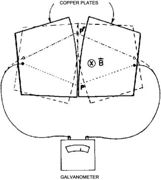
In Figure 1 two copper plates with slightly curved edges are rocking back and forth between the solid and the dashed lines in a uniform magnetic induction field directed into the paper. Each plate is connected to one of the terminals of a voltmeter or galvanometer. The plates make contact at the point P initially
How to cite this paper: Young, F.J. (2018) A Corrected EMF Problem. Open Access Library Journal, 5: e4270.
https://doi.org/10.4236/oalib.1104270 Received: December 19, 2017
Accepted: January 28, 2018 Published: January 31, 2018 Copyright © 2018 by author and Open Access Library Inc.
This work is licensed under the Creative Commons Attribution International License (CC BY 4.0).
http://creativecommons.org/licenses/by/4.0/
DOI: 10.4236/oalib.1104270 2 Open Access Library Journal Figure 1. Rocking plates.
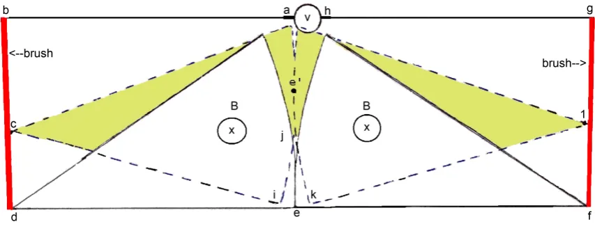
DOI: 10.4236/oalib.1104270 3 Open Access Library Journal in flux in the area between the dashed and dotted lines comprising the leads on the right side. This would lead to the very small potential Feynman et al. ob-served. If the leads were stiff and the contacts were connected to brushes at the edge of each plate the leads would not move and there would be no EMF at all generated. A slightly different configuration of these plates is shown in Figure 2. It has no leads that move as the plates are rocked. The line abcdefgh shows the base of the red plates at rest and that line is the most direct way for current to flow to the red brushes and around the loop through the voltmeter. There is a magnetic induction, B directed into the paper. The plates are moved approx-imately fifteen degrees and are depicted in that position by dashed lines and the part that would stick out where there are two sets of plates is colored a light green. Initially the path from the voltmeter is given by abcdefgh. As the plates move from the initial position the path becomes abcije’klgh around the loop through the voltmeter. Along this path − Φd dt=0. The only point at which the right and left plates touch is at point e’. Faraday’s Law can be applied only if there are no breaks in the path. The v× ⋅B dl on the left plate cancels the same
term on the right plate. Thus Faraday’s law yields zero EMF. An observer might be stationed on either the left or the right conducting plate or on the external circuit comprising the brushes and the voltmeter leads. As illustrated many times [2][3], all observers must agree on the EMF produced. The ones sitting on the plates would have to completely evaluate
EMF d d
S
= − ∂ ∂ ⋅
∫
B t S+
∫
v B× ⋅ (1)along a path and embraced area including the brushes and voltmeter leads. This equation is derived by Young [3]. The derivation is repeated below. The observer on the external circuit, however, sees no time rate of change in the magnetic in-duction flux if he takes the correct path. His circuit goes counter clockwise from the left terminal of the voltmeter to the left brush, passing through points ab-cdeflgh through the right brush to the right terminal of the voltmeter. Thus the
[image:3.595.109.536.547.713.2]EMF=0 regardless of the movement of the plates and independent of their magnetic relative permeability. This is the easy solution.
DOI: 10.4236/oalib.1104270 4 Open Access Library Journal
3. Electromotive Force with Relative Motion between Circuit
Parts
We develop a definition for the electromotive force about any closed metallic circuit whose various parts may be moving relative to each other and which may or may not contain sliding contacts. Once again the desired definition of EMF must be consistent with Kirchhoff’s Law. When there is relative motion between parts of the circuit the resistance of a segment must be defined in such a way that it does not change if the segment is moving. That is, if one wishes to retain the formula for the dissipation in an element as 2
I R and because both the
dissipa-tion and the current are independent of the observer, it follows that the resis-tance to be used in this formula should be the same as the resisresis-tance calculated by an observer stationary with respect to that element. In that case the resistance of any element is defined as
d d
i
i i
R = ′⋅ l ′⋅
∫
E ∫
J S (2) where the primes denote that the fields are measured by an observer at rest with respect to the conductor at the point dl. (if the conductor is flexible it can beconsidered as comprising an infinite number of increments each of which has a resistance that is evaluated by an observer on that particular increment.) Because the current flowing through a conductor is independent of the observer, the IR drops about the circuit can be written as
d d d
d d
i i
i i i i i
i i
I R l
l l ′ ′ ′ = ⋅ ⋅ ⋅ ′ ′ = ⋅ = ⋅
∑
∑ ∫
∫
∫
∑∫
∫
J S E J S
E
E(3)
It thus appears that a reasonable definition of the electromotive force about any prescribed path in a non-rigid, conducting circuit is given by
d
e
=
∫
E
′
⋅
l
(4)where E′ is defined as the electric field intensity evaluated at the element dl
by an observer stationary with respect to the conductor at that point. To avoid having to use several reference frames in evaluating Equation (4),
′ = + ×
E E v B (5)
Equation (5) from the special theory of relativity can be used to transform each element of Equation (4) to single given reference system. The fields meas-ured by an observer in this fixed reference frame will be denoted by the un-primed quantities. By solving Equation (5) for E and substituting it into the Maxwell equation ∇ × = −∂ ∂E B t, there results
(
)
′∇ ×E = −∂ ∂ + ∇ × ×B t v B (6)
re-DOI: 10.4236/oalib.1104270 5 Open Access Library Journal sults
d d
S
e= − ∂ ∂ ⋅
∫
B t S+
∫
v× ⋅B l (7)where B is the total magnetic induction field due to all causes and has been assumed to be independent of the observer.
v is the velocity of the segment of the conductor at the point corresponding to dl relative to some given observer. (Note carefully that v is the velocity of the conductor and not the velocity of the path element dl in case the two differ
as will be shown in later examples.)
∂ ∂B t is the vector time rate of change of B relative to the same observer. Warning!! This formula has been derived from the results of the Special Theory of Relativity and hence is strictly justified only for the case of uniform motion. However, it is found experimentally to hold with negligible error for all accelerations that are physically attainable in the terrestrial laboratory. The re-sulting error only can be found from The General Theory of Relativity.
Once again the expression for the electromotive force (EMF) as exhibited in Equation (7) contains a surface integral and hence can be evaluated only for a closed circuit. It is nevertheless possible to define a unique potential difference between the terminals of a generator, just as in the case of rigid circuits. These terminals and the external circuit must lie within a region that to some observer is irrotational and that observer must see no part of the external circuit moving through a magnetic field. In other words, if it is possible to connect these ter-minals with a rigid line so that there is no EMF in any closed circuit formed by this line and any permitted external circuit, then it is possible to uniquely de-fine a terminal voltage which is equal to the EMF (computed about the inter-nal circuit and this rigid line) minus the IR drop in the generator: e.g.
d
B
AB A
V = −
∫
E⋅ l. As before the sign convention is such that the line integral ofEquation (4) is taken as positive in the direction going from the negative terminal, A, through the generator to the positive terminal, B, and d
B
A
l ′⋅ ′
∫
E is taken from A to B through the generator.This section is restricted to cases where any segment of the circuit moving rel-ative to any observer through a magnetic field is a conductor. The case of a di-electric moving through a magnetic field has been presented by Young [3].
4. Conclusion
cur-DOI: 10.4236/oalib.1104270 6 Open Access Library Journal rent is expected to flow. Numerous examples are given in the scientific literature [2][3].
References
[1] Feynman, R.P., Leighton, R.B. and Sands, M. (1964) The Feynman Lectures on Physics, The EM Field. Addison-Wesley Publishing Company, Inc., Reading, Mas-sachusetts, 17-2 - 17-3.
[2] Hughes, W.F. and Young, F.J. (1966) The Electromagnetodynamics of Fluids. John Wiley & Sons, Inc., New York, 28-33.
[3] Young, F.J. (2012) Magnetically Induced Electromotive Force. Xlibris Corp.