Figure 1 Distribution of atmospheric melting points of organic components (after Matsuoka and Fukushima, 1986).
Melt Crystallization
P.J.Jansens, Delft University of Technology, The Netherlands
M.Matsuoka, Tokyo University of Agriculture and Technology,Japan
Copyright^ 2000 Academic Press
Introduction
Melt crystallization, sometimes referred to as ‘frac-tional crystallization,’ is a collective term for physical separation processes aimed at puriRcation of organic compounds from a multi-component mixture by crys-tallization without addition of a solvent. The driving force for crystallization is created by cooling, evapor-ating or pressuring the melt.
The main advantage of this separation technique is the superior selectivity of the crystallization process caused by restricted mobility in the crystal lattice and strong molecular bonds. The energy consumption can be low because the heat of fusion of most organic compounds is two to four times smaller than their heat of evaporation and the operating conditions are gener-ally mild. Fingener-ally, the absence of hazardous solvents is important from an environmental point of view. Dis-advantages are the inherent slowness of crystal growth leading to voluminous equipment and the need for intensive slurry handling in certain process designs.
Balancing the merits and drawbacks, melt crystalli-zation is usually applied for ultrapuriRcation ('99.99%), separation of isomers and puriRcation of thermally unstable components. Some examples of industrial applications are acrylic acid, bisphenol A, caprolactam, cresol, dichlorobenzene, fatty acids, naphthalene, parafRn and xylene.
In this chapter, the designs of conventional and emerging melt crystallization processes are described and evaluated. Also the relatedReld of freeze-concen-tration of aqueous solutions is brieSy touched upon. Extensive coverage of all types of equipment on dif-ferent scales is beyond the scope of this article. There is a focus on large-scale applications with a bias on state-of-the-art equipment provided by equipment manufacturers rather than the proprietary processes of end-users. More elaborate overviews of the prin-ciples and applications of melt crystallization are given in the Further Reading.
Theory
The technical feasibility and economic viability of separation and puriRcation of an organic mixture by
melt crystallization entirely depend on its solid}liquid phase equilibrium (SLE). A survey of SLE data in 1986 demonstrated that more than 70% of organic substances have melting points between 03C and 2003C, indicating that no special thermal media are needed to achieve separation (Figure 1).
The classiRcation of about 1500 binary systems in the International Critical Tables (Figure 2) has re-vealed that more than 50% form simple eutectic mixtures and 25% form an intermolecular solid com-pound which forms simple eutectics with the two constituent components. This type also includes the formation of more than two solid compounds. The formation of a pure solid phase in one crystallization step is feasible for roughly 85% of the systems. The formation of solid-solutions is limited to only 10%, for which complete separation in a single crystalliza-tion step is fundamentally impossible.
Even for eutectic systems, however, the product from industrial crystallizers is not 100% pure. This is caused by the adherence of mother liquor to the crystal surface and by the inclusion/entrapment of mother liquor inside the crystals. Further puriRcation is required and this can be achieved by washing and by sweating.
E Washing is done by contacting the crystals with a fresh solvent or, preferably, with pure melted product. This operation removes adhering impu-rities and is widely used in commercial plants. E Sweating can be induced by exposing the impure
Figure 2 Distribution of binary phase diagrams of organic mixtures (after Matsuoka and Fukushima, 1986).
melt preferentially due to a lower melting point. The impure liquor comes out of the crystalline body through cracks and pores. Sweating can also be applied to solid solution systems and plays an important role as a puriRcation mechanism in layer and suspension growth processes.
Process and Equipment Design
Indirect coolingis the most widely applied technique to produce crystals from a melt. In this context the term ‘indirect’ refers to the mechanism of heat trans-fer from the melt to the cooling medium, which takes place via the wall of a heat exchanger. Crystal growth may either take place as a layer on a cooled surface or freely suspended in the mother liquor. The principles of both techniques and their large-scale applications are discussed below. SeeTable 1for an overview and an evaluation of both techniques.
Layer Growth
In this technique the crystals grow as a layerRxed and perpendicular to a cooled wall. The heat of crystal-lization is removed through the crystal layer and the wall. At low growth rates (typically(10\7m s\1) and proper mixing of the mother liquor, a stable crystal morphology can be maintained, which results in a good selectivity of the crystallization step. In industrial practice, however, very high growth rates (10\6}10\5m s\1) must be applied leading to roughening of the crystal surface (cellular and den-dritic growth) and consequently to entrapment of impure liquor in the layer. High growth rates are required to achieve a reasonable productivity since the growth area is limited to the heat-exchange area (4100 m2m\3).
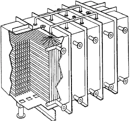
Industrial layer growth equipment is normally operated batch-wise, whereby static and dynamic processes can be distinguished. Instatic equipment, crystal growth occurs from a stagnant melt. Commer-cial equipment is manufactured by BEFS Technolo-gies (France) and Sulzer Chemtech (Switzerland). Their similar designs feature a closed rectangular vessel equipped with a high heat-exchange area in the form ofRnned tubes or structured plates (Figure 3). One full operating cycle takes about one day and comprises Rve steps: (1) Rlling of the vessel, (2) crystallization by programmed cooling, (3) sweating by gradual heating, (4) draining of residual mother liquor and (5) melting and draining of the product layer. Equipment sizes range from 0.1 to 35 m3. Typical growth rates are in the order of 10\6m s\1 but the overall separation efRciency of a full operat-ing cycle is relatively good (up to 99.9 wt% product purity).
Indynamic processes, there is forced mixing of the mother liquor during the crystallization step. The mixing is usually achieved by circulating the liquor as a fallingRlm or as a fully developedSow over vertical heat-exchanger tubes. Other designs whereby mixing was achieved by stirring, pulsation or bubbling-through an inert gas, were not successfully commer-cialized. Sulzer Chemtech provides the dynamic fallingRlm system whereby both the melt as well as the coolant are circulated as fallingRlms over the tube wall (Figure 4).
Table 1 Comparison of layer and suspension growth processes (values represent order of magnitude; operation/maintenance relative to distillation)
Parameter Layer growth Suspension growth
Crystal surface area Up to 100 m2m\3 Up to 10 000 m2m\3
Growth rate 10\6}10\5m s\1 10\8}10\7m s\1
Mixing intensity Poor (static)/good (dynamic) Good
Separation efficiency Good (static)/moderate (dynamic) Excellent
Product purity in one stage 499.9% 599.95%
Mode of operation Repetitive batch Once through, continuous
Heat transfer coefficient &200 W m\2K\1 &1250 W m\2K\1
Energy efficiency Good (static)/moderate (dynamic) Good
Slurry handling No Yes
Solid}liquid separation No Yes
Design Simple Complex
Operational attention Normal Above average
Maintenance intensity Normal Above average
Scale-up Mutiplication of units Engineering
Economy of scale Not good Good
World-scale plant capacity &150 kT year\1 &350 kT year\1
Feed concentration Preferably'90% Preferably(99%
Viscosity (10 cP (50 cP
Purification of solid solutions Suitable Less suitable
[image:3.568.58.274.492.693.2]Freeze concentration Less suitable Suitable
Figure 3 Static crystallizer. (Courtesy of Sulzer Chemtech.)
Figure 4 Dynamic falling film crystallizer. (Courtesy of Sulzer Chemtech.)
The overall separation efRciency of one dynamic operating cycle is moderate relative to a static process but the short cycle time makes the dynamic process well suited to sequential countercurrent staging. Stag-ing requires intermediate storage tanks but makes it possible to produce ultrapure products at good
recov-ery. The stages are actually operating cycles which can be executed in the same crystallizer (Figure 5).
[image:3.568.296.517.498.680.2]Figure 5 Multistage operation of layer growth processes (tem-peraturesT1(T2(T3).
Figure 6 Heat integration of dynamic falling film crystallizers. (Courtesy of Sulzer Chemtech.)
addressed by the introduction of heat integration in 1996. The principle is based on a heat pump where a crystallizer alternatively acts as a condensor or as an evaporator for the cooling agent (Figure 6).
Continuous processes, whereby the layer growth occurs on a rotary drum or an endless belt, have been designed but are not applied commercially for puriR -cation of organics for various reasons (low selectivity, mechanical complexity, economy of scale).
Static and dynamic layer growth equipment are applied commercially to a wide range of products (e.g. acrylic acid, p-xylene, naphthalene, bisphenol A and parafRn). A relatively high feed purity is re-quired, particularly for the dynamic processes, since this promotes the adhesion of the crystal layer to the cooled surface.
Suspension Growth
In this technique, the crystals form and grow freely suspended in the mother liquor. The heat of crystalli-zation is absorbed by the supercooled liquor. High
speciRc productivity can be achieved at low growth rates because the crystal surface area is very large (up to 10 000 m2m\3). Typical growth rates in industrial units are only 10\8}10\7m s\1which contributes to an excellent selectivity of the crystallization process. Suspension growth processes generally comprise separate sections for crystallization and solid}liquid separation. The effectiveness of the Rnal solid} liquid separation has a major impact on the overall separation efRciency. The design of the crystallization section should be focused therefore on producing crystals with a goodRlterability which means essen-tially growing large crystals with a narrow size distri-bution. The fundamentals of modelling particulate processes are also applicable to suspension growth from the melt.
Crystallization section Single-stage crystallization is often unfavourable because the nucleation and growth of all crystals occurs at the lowest operating temperature, which is determined by the yield, from an impurity-rich mother liquor. The simplicity of this design often does not outweigh the potential disad-vantages:
E poor Rlterability of crystals due to high nuclea-tion : growth ratio;
E reduced selectivity due to inclusion or incorpora-tion of impurities;
E moderate energy efRciency; E difRcult solid}liquid separation.
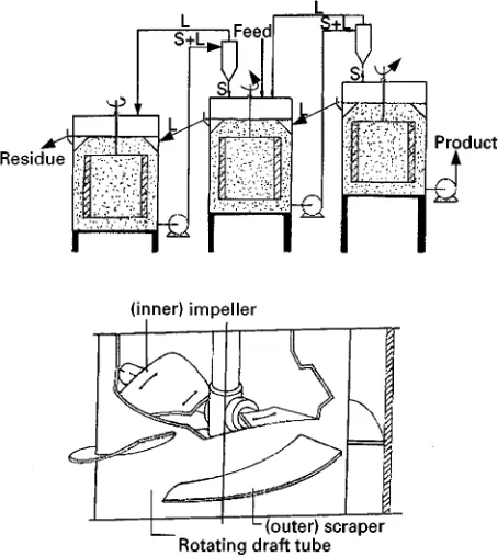
Cascades of crystallizers, operated either cocurrent or countercurrent, are found in most processes. In cocurrent cascades crystals and mother liquor are transported in parallel from stage to stage at decreas-ing temperature. The GMF-CDC (Figure 7) is an example of a cocurrent cascade, where the crystal slurrySows freely from one compartment to the next via openings in the cooling elements. Along theSow direction, the impurities are concentrated in the mother liquor but the nucleation rate and the crystal growth rate decrease. As a result, theRlterability of the crystals improves throughout the cascade while a good selectivity is maintained. The product crystals suspended in the impure mother liquor are with-drawn from the cold end of the cascade, which is a major drawback for solid}liquid separation.
[image:4.568.51.279.452.683.2]Figure 7 Cocurrent cascade of crystallizers. (Courtesy of GMF-Gouda.)
[image:5.568.291.518.59.313.2]Figure 8 Countercurrent cascade of crystallizers. (Courtesy of Tsukishima Kikai Co. (TSK).)
Table 2 Comparison of crystallization sections consisting of a single-stage, a cocurrent cascade or a countercurrent cascade
Parameter Single Cocurrent Countercurrent
Operating temperature Constant low Decreasing Increasing
Product withdrawal Cold Cold end Hot end
Product crystal filterability Moderate Good Good
Product liquor Impure Impure Relatively pure
Internal slurry handling None Limited Intensive
Equipment and process design Simple More complex Complex
part of the crystal production occurs at high temper-ature from a relatively pure mother liquor. PuriR ca-tion of the crystals by Ostwald ripening (growth of large crystals by dissolution ofRnes driven by a reduc-tion of surface energy) can play a role but it is doubt-ful whether there is a contribution from sweating. Product withdrawal occurs from the hot end, which simpliRes solid}liquid separation.
A comparison of cocurrent and countercurrent crystallizers is shown inTable 2.
Solid}liquid separation section Product recovery is more and more executed in wash columns, which combine an effective solid}liquid separation with a pure melt wash and a single recrystallization step. The principle of wash columns is illustrated by Fig-ure 9. A crystal slurry is pumped into the column, where the mother liquor escapes via a Rlter leaving behind the crystals as a packed bed. This bed is transported upwards by means of a rotating screw. At the top, the crystals are scraped off, suspended in wash liquid (recycled pure melt) and melted in an external melter. The wash-liquid circuit is kept press-urized, which causes the wash liquid to Sow down-ward (reSux). The wash liquid does not leave the column but recrystallizes on the cold crystal bed, thereby producing the so-called ‘wash front’. This front marks steep gradients in concentration, temper-ature and porosity.
The crystal bed can be transported under gravity, by hydraulic pressure or via a mechanical aid (screw/piston). The direction of transport is normally downwards for organic crystals and upwards for ice. If the temperature of the feed slurry is low (single-stage or cocurrent cascade crystallization), more wash liquid will recrystallize causing a large drop in porosity over the wash front. At a given transport force exerted on the crystal bed, the throughput re-duces with decreasing porosity due to an increased back-pressure from the wash liquid. Alternatively at constant throughput, the compressive stresses exerted on the crystals increase considerably which may result in deformation of some organic crystals, which are mechanically weak. Ideally, the temperature in-crease over a wash column should be 2}53C.
[image:5.568.52.517.620.711.2]Figure 9 Principle of wash column. (Courtesy of Niro-PT.)
Table 3 Comparison of wash columns
Parameter Gravity Hydraulic Mechanical
Height : diameter ratio 4}6 1 1
Minimum crystal size 500m 150m 150m
Residence time: whole column 1 h 10}15 min 10}15 min
Residence time: wash section 30 min 3}5 min 3}5 min
Purification mechanism Washing and sweating Washing Washing
Maximum temperature rise 10}153C 5}103C 5}103C
Compressive stress Negligible Considerable Considerable
Capacity 500}1500 kg m\2h\1 5000}10 000 kg m\2h\1 5000}10 000 kg m\2h\1
Scale-up Proven to 2 m Under study Proven to 1.2 m
[image:6.568.54.517.581.713.2]Equipment design Simple More complex Complex
Figure 10 Classification of wash columns based on the crystal transport mechanism (after Jansens and Van Rosmalen, 1994).
heat-transfer limitation in the solid phase may be neglected. In the more densely packed hydraulic and mechanical wash columns, puriRcation occurs almost exclusively by displacement washing. In the loosely packed gravity wash columns, further puriRcation by sweating occurs because of the longer residence time. Gravity and mechanical wash columns have been commercialized by TSK and Niro-PT, respectively. TNO (Netherlands) has developed a hydraulic wash column equipped with separateRlter tubes. See Fig-ure 10andTable 3for a more detailed comparison. Suspension growth equipment is applied commer-cially to purify various organic products (e.g. p -xylene, naphthalene andp-dichlorobenzene) but also for concentration of aqueous solutions (freeze con-centration, see below). There are virtually no restric-tions on feed purity, while a product purity
599.99% is feasible.
Column crystallizers Column crystallizers are de-signs where a single-stage crystallizer and a gravity-wash column have been integrated in one shell (similar to distillation columns). The back-mixing column, for example, has been successfully commercialized by Nippon Steel Chemical Co. (Japan) for the puriRcation of naphthalene. The
pro-duction rate is limited by the capacity of the wash columns (41500 kg m\2h\1). A new development by Matsuoka is the inclined column crystallizer. The inclination promotes settling and reduced axial dispersion (Figure 11).
Alternative Process Designs
Evaporative Melt Crystallization
Direct cooling is the driving force for evaporative crystallization. The heat of crystallization is with-drawn by evaporation of a portion of the mother liquor, which is induced by a reduction of the operat-ing pressure. The vapour phase is condensed in an overhead condensor and reSuxed to the crystallizer. Crystal formation and growth take place freely sus-pended in the bulk of the mother liquor. The main advantage of direct over indirect cooling is that the heat of crystallization is transferred to the cooling medium via a clean condensing duty rather than via a (scraped) heat exchanger. Hence the heat transfer is more effective while the design and scale-up of equip-ment can be simpliRed.
Figure 11 Inclined column crystallizer. (A) Schematic pre-sentation of flows. (B) Experimental facility. (Reproduced with permission from Matsuoka M, Takiyama H and Soutome O (1997) Separation characteristics of an inclined column crystallizer. Transactions of the Institution of Chemical Engineers 75(A): 206}212.)
Figure 12 Continuous evaporative crystallization. ML, mother liquor; Con., condensate; Prod., product; STM, steam; CW, cool-ing water. (Courtesy of Tsukishima Kikai Co. (TSK).)
environment, product purity). The potential of ap-plying direct cooling to melt crystallization, however, was not recognized until recently.
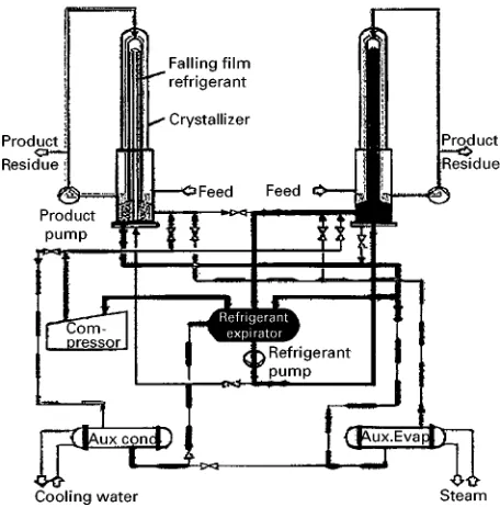
In 1993 TSK proposed a puriRcation processes based on evaporative melt crystallization for cap-rolactam, acrylic acid and bisphenol A. Figure 12 illustrates the set-up of a continuous process featuring a single-crystallization stage and a wash column (puriRer).
In recent years, a batch-wise evaporative melt-crys-tallization process with caprolactam}water as a model system has been developed and optimized. Figure 13
shows the pressure temperature}fraction temperature (PT}XT) phase diagrams where the three-phase equi-librium curve (ScLV) stretches from the triple point of caprolactam (Tc) to the quadruple point of the binary system (Tq). Lowest operating cost can obviously be achieved near 5 wt% water, where the operating pres-sure is maximum and the temperature fairly high. Deep vacuum would be required for water concentra-tions below 1 wt% and above 20 wt%. Operating at a high temperature generates cost savings for the condensor (low area, no chilled cooling water).
Figure 14 shows the PT-trajectory for the batch-wise crystallization of caprolactam from a melt con-taining 4 wt% of water. Starting from point A, the pressure in the crystallizer is reduced until the va-pour}liquid equilibrium is reached at point B and the melt starts to boil. Upon a further reduction of pres-sure, the evaporation of mainly water causes the melt to cool down but the composition of the melt does not change since the vapour is condensed and re-Suxed. At point C the solid}liquid}vapour equilib-rium is reached and caprolactam starts to solidify. From C to D the crystal content steadily increases to 20 wt%, while the water concentration in mother liquor increases to 5 wt%.
Scale-up to 50}100 m3 crystallizers appears to be feasible, which is world scale for suspension crystalli-zation equipment. Until now, there are few commer-cial installations with limited capacity. TSK has installed two units for caprolactam with a capacity of 2500 tons per year.
Pressure Crystallization
In this technique, crystallization is induced by com-pression rather than by cooling. The solid phase of most (organic) materials has a higher density than the liquid phase and consequently the melting point rises with increasing pressure. Benzene, for example, has an atmospheric melting point of 5.53C but solidiRes at room temperature when the pressure is about 2 MPa. Not only the melting points but also solid}liquid phase equilibria shift upward upon a pressure increase, which is illustrated for a mixture of cresols inFigure 15.
An additional advantage of pressure crystallization is found in the transmission of pressure being much faster than the transfer of heat in both liquid and solid phases. This means that a uniform pressure can be established quickly throughout the system. Therefore local variations in supercooling of the mother liquor can easily be avoided.
Figure 13 Pressure}temperature}composition diagram of -caprolactam}water. Tt,i"triple point component i; Tq"
quadru-ple point; Tcrys"crystallizer temperature; Tcon"condenser
tem-perature; Si, Li, Vi"solid, liquid, vapour phase component i; (LV)i,
(SL)i, (SV)i liquid}vapour, solid}liquid, solid}vapour equilibrium
curves pure component i; x, y"liquid, vapour concentration (wt%) at three-phase equilibrium; SiLV"three-phase equilibrium
[image:8.568.52.276.61.315.2]line with solid phase of component i. (Reproduced with per-mission from Diepen PJ (1998)Cooling Crystallization of Organic Compounds. PhD thesis, Technical University Delft.)
Figure 14 Part of pressure}temperature diagram of -caprolac-tam}water. (Reproduced with permission from: Diepen PJ (1998) Cooling Crystallization of Organic Compounds. PhD thesis, Tech-nical University Delft.)
Figure 15 Phase diagram of mixture ofp-cresol and m-cresol. (Reproduced with permission from Yasuda M, Sato Y and Suematsu H (1991)p-Cresol with high pressure crystallization. Kagaku Kogaku 55(4): 290}291.)
(Japan) developed in the 1970s a pressure-crystalliza-tion process, which was applied for the separapressure-crystalliza-tion of p-cresol from its isomers on a commercial scale. A given amount of slurry from a chiller is fed to a cylindrical pressure vessel, compressed to crystallize and drained to remove residual impure melt ( Fig-ure 16). During the subsequent depressuring, puriR -cation by sweating can occur. Finally, a cylindrical block of puriRed crystals is taken out as the product. The operating temperature is 62.53C at 200 MPa (versus 12.53C at atmospheric pressure) which effectively reduces the viscosity of the mother liquor. Under these conditions, the selectivity and the rate of crystal growth rate are enhanced while solid}liquid separation is facilitated. PuriRcation by sweating dur-ing depressurdur-ing is analogous to (thermal) sweatdur-ing at elevated temperatures.
The features of pressure crystallization can be sum-marized as follows:
E batch-wise operation;
E product purity up to 99.5%, feasible in one operat-ing cycle from 70 to 80% in feed;
E high yield, limited only by the solid}liquid equilib-rium of a given system;
E short cycle times, only a few minutes per cycle, due to rapid penetration of pressure;
[image:8.568.298.508.417.665.2]Figure 16 Operating cycle of pressure crystallization process. (Reproduced with permission from Yasuda M, Sato Y and Suematsu H (1991)p-Cresol with high pressure crystallization. Kagaku Kogaku 55(4): 290}291.)
Figure 17 A three-stage countercurrent freeze concentration process. (Courtesy of Niro-PT.) (A) Simplified process flow scheme. (B) Cross-section of a scraped surface heat exchanger.3Bx is a measure for concentration of water phase (based on the breaking index).
E simple process design}crystallization, separation and sweating are carried out in a single vessel; E complex mechanical design } materials selection
and construction of mechanical parts are critical factors for success.
The scale-up of pressure-crystallization equipment is not easy due to mechanical complexity, and it becomes increasingly difRcult at larger vessel dia-meters to remove residual melt from the centre of the cake by compression. The production capacity of a single plant is in the order of 500 tons per year.
Freeze Crystallization
Freeze concentration is a separation technology aimed at concentration of aqueous solutions by means of cooling crystallization. This technology is closely related to melt crystallization based on
sus-pension growth in terms of process synthesis and equipment design.
Commercial processes feature a countercurrent cas-cade of crystallizers while theRnal solid}liquid separ-ation takes place in mechanical wash columns ( Fig-ure 17). Indirect cooling is usually preferred over direct cooling to prevent contamination of the concentrate and to contain the volatile components. Large spherical ice crystals can be grown relatively easily through Os-twald ripening. The individual stages of the cascade therefore feature separate sections for nucleation and growth. Crystallization (nucleation) takes place on the surface of the external scraped surface heat exchangers. Ripening (growth) occurs in large stirred vessels.
[image:9.568.56.519.528.674.2]Traditionally, most applications are found in the food industry for the concentration of fruit juice, wine, beer and coffee extract. In thisReld, the advant-ages of freeze concentration over competing tech-nologies (membranes and evaporation) are the superb preservation of aromas and colour while decay reac-tions are slowed down by the low operating temper-ature.
Recently, world-scale installations have come on-stream where wastewater from chemical plants is concentrated. The produced melt water can be re-used as process water while the residual concentrate is incinerated. Here the advantages of freeze concen-tration are the low energy costs and the capability to concentrate beyond the eutectic point, where salts start to precipitate.
Drawbacks of freeze crystallization are the rela-tively high investment cost and the above-average maintenance intensity (there are many pieces of rotating equipment).
Conclusion and Future Outlook
Melt crystallization is the third most applied physical separation technology after distillation and extrac-tion. Conventional processes are based on layer or suspension growth by indirect cooling.
E Layer growth may be considered as proven and mature technology, whereby the absence of slurry handling is a major advantage. Fully automated semi-continuous units can be delivered as turnkey projects. The need for repeated recrystallization steps to achieve a high product purity, however, increases both investment and operating cost. The desire to develop economically attractive continu-ously operated equipment seems to be in conSict with the basic characteristic of layer growth on a cooled surface.
E Suspension growthis also proven but not yet ma-ture technology. The superior selectivity and high
speciRc productivity of crystal growth in a suspen-sion create a huge potential, which can be further exploited by simpliRcation of equipment design and minimization of slurry handling.
E Evaporative melt crystallizationis a relatively young technology which combines the merits of suspension growth with a minimum of slurry handling. For certain applications, such as caprolactam, this tech-nique is expected to take off in coming years. E Pressure crystallization is an alternative
techno-logy, which is well suited to purify components with a very low melting point at ambient temper-ature but elevated pressure. Outside this niche use, pressure crystallization probably cannot compete with indirect/direct cooling crystallization due to high equipment cost.
See Colour Plate 36.
Further Reading
Arkenbout GF (1995) Melt Crystallization Technology. Basel: Technomic Publishing AG.
Jansens PJ and Van Rosmalen GM (1994) Fractional crys-tallisation. In: Hurle DJT (ed.) Handbook of Crystal Growth, Vol. 2A, ch. 6. Amsterdam: Elsevier Science. Matsuoka M and Fukushima H (1986) Determination of
solid}liquid equilibrium.Bunri Gijutsu(Separation Pro-cess Engineering) 16: 4}10.
Matsuoka M, Takiyama H and Soutome O (1997) Separ-ation characteristics of an inclined column crystallizer. Transactions of the Institution of Chemical Engineers 75(A): 206}212.
Moritoki M (1984) Crystallisation and sweating ofp-cresol by application of high pressure.Industrial Crystalliza-tion84: 369}380.
Randolph AD and Larson MA (1988)Theory of Particulate Processes, 2nd edn. San Diego: Academic Press. Sloan GJ and McGhie AR (1988)Techniques of Melt
Crys-tallization. New York: John Wiley.
Yasuda M, Sato Y and Suematsu H (1991)p-Cresol with high pressure crystallization.Kagaku Kogaku55(4): 290}291. Zief M and Wilcox WR (1967)Fractional SolidiTcation.
New York: Marcel Dekker.
Polymorphism
M. R. Caira, University of Cape Town, Rondebosch, South Africa
Copyright^ 2000 Academic Press
Introduction
When the molecules of a chemical substance are able to crystallize in more than one three-dimensional