Effective long-range interlayer interactions and electric-field-induced subphases in ferrielectric
liquid crystals
A. D. L. Chandani,1,2Atsuo Fukuda,1,*Jagdish K. Vij,1,†Yoichi Takanishi,3and Atsuo Iida4
1Department of Electronic and Electrical Engineering, Trinity College, The University of Dublin, Dublin 2, Ireland
2Department of Chemistry, University of Peradeniya, Peradeniya, Sri Lanka
3Department of Physics, Kyoto University, Kyoto 606-8502, Japan
4Photon Factory, Institute of Materials Structure Science, High Energy Accelerator Research Organization, Ibaraki 305-0801, Japan
(Received 30 October 2015; revised manuscript received 27 January 2016; published 19 April 2016) Microbeam resonant x-ray scattering experiments recently revealed the sequential emergence of electric-field-induced subphases (stable states) with exceptionally large unit cells consisting of 12 and 15 smectic layers. We explain the emergence of the field-induced subphases by the quasimolecular model based on the Emelyanenko-Osipov long-range interlayer interactions (LRILIs) together with our primitive way of understanding the frustration in clinicity using theqEnumber defined asqE= |[R]−[L]|/([R]+[L]); here [R] and [L] refer to the numbers of smectic layers with directors tilted to the right and to the left, respectively, in the unit cell of a field-induced subphase. We show that the model actually stabilizes the field-induced subphases with characteristic composite unit cells consisting of several blocks, each of which is originally a ferrielectric three-layer unit cell stabilized by the LRILIs, but some of which would be modified to become ferroelectric by an applied electric field. In a similar line of thought, we also try to understand the puzzling electric-field-induced birefringence data in terms of the LRILIs.
DOI:10.1103/PhysRevE.93.042707
I. INTRODUCTION
A series of experimental studies [1–4] has revealed the sequential emergence of temperature-induced biaxial and uniaxial subphases as a result of degeneracy lifting due to long-range interlayer interactions (LRILIs) at the frus-tration points among antiferroelectric smectic-CA∗ (Sm-CA∗), ferroelectric Sm-C∗, and paraelectric Sm-A phases [5–10]. The biaxial subphases have nonplanar superlattice structures with highly distorted microscopic short-pitch helical director arrangements in unit cells consisting of several smectic layers [11–23]. Since the deviation from the planar structures is not really large, however, the biaxial subphases are appropriately specified by a relative ratio of ferroelectric and antiferroelectric orderings in the unit cell
qT = [F]
[A]+[F]. (1) Here qT typically increases monotonically from 0 in the antiferroelectric Sm-CA∗ phase to 1 in the ferroelectric Sm-C∗
phase with rising temperature, as the degeneracy lifting is frequently due to weak LRILIs at the frustration point between the main phases Sm-CA∗ and Sm-C∗ [1–4]. Subphases with smaller unit cells of irreducible qT in lower terms in the denominator must be observed more easily, whereas those with larger unit cells of irreducible qT in higher terms in both the numerator and denominator may be suppressed by a number of factors including surface and finite-size effects and thermal fluctuations. Experimentally, seven subphases with
qT =1/5, 1/4, 1/3, 2/5, 1/2, 3/5, and 2/3 are considered to exist [1–4,23–27].
*[email protected] †[email protected]
In this paper we study the electric-field-induced subphases (stable states) and their emerging sequences along a similar line of thought. Increasing applied electric field produces nearly the same effects as increasing temperature; both favor the ferroelectric state. Since an applied electric field selectively determines the director tilting sense, we should use
qE= |
[R]−[L]|
[R]+[L] (2)
instead of qT; here [R] and [L] refer to the numbers of smectic layers with directors tilted to the right and to the left, respectively, in the unit cell of a field-induced subphase.1 Sequential characteristics of the field-induced transitions have been observed in several temperature-induced subphase regions at zero electric field,qT =1/4, 1/3, 1/2, 3/5, and 2/3, from the early stage of investigation [1–4,27–32]. All of the antiferroelectric phases,qT =0 (Sm-CA∗), 1/4, 1/2, and 2/3, must haveqE=0 at zero electric field, whereas ferrielectric and ferroelectric phases,qT =1/3, 3/5, 2/3, and 1 (Sm-C∗), must haveqE=1/3, 1/5, 1/3, and 1, respectively. The LRILIs are usually weak and henceqE may increase monotonically with increasing applied electric field.
Sandhyaet al.recently found a fairly conspicuous example of the field-induced transition fromqE=1/5 (qT =3/5) to
qE=3/5, which is considered to occur by flipping only one layer in the five-layer unit cell of the temperature-induced subphase with qT =3/5 [27]. Sandhyaet al.also observed at least two, probably three field-induced subphases in the transition from qE=1/3 (qT =1/3) to qE=1 (Sm-C∗)
1Whenq
[4,32]. Prior to these observations having been reported, the general view seemed to have been that on applying the field
qE=1/3 (qT =1/3) went directly toqE=1. Conceivable simpleqE’s in this case are 1/3, 1/2, 3/5, 2/3, etc., although it may directly change into the unwound Sm-C∗ phase by simultaneously flipping one layer in the simple three-layer unit cell of the temperature-induced subphase withqT =1/3. Actually, however, Sandhyaet al.pointed out some sequential characteristics of the field-induced subphase emergence that may indicate the stable existence of at least two subphases before the field-induced transition into the unwound Sm-C∗
phase. We were wondering at that stage of our work what unit cells constituted these field-induced subphases.
Microbeam resonant x-ray scattering (RXRS) experiments brought about a breakthrough in confirming the emergence of the field-induced subphases that have unbelievably large 12- and 15-layer unit cells [33]. Moreover, they clarified the approximate planar superlattice structure of the 12-layer unit cell withqE=2/3: It consists of four blocks, each of which is originally ferrielectric 3-layer unit cells stabilized by the LRILIs, but with two consecutive blocks that would be modi-fied to become ferroelectric by an applied electric field. There are several theoretical approaches to describe the sequential phase transitions in polar smectic liquid crystals, but only two of them have presented definite results that can be compared with the experimental ones. One is the phenomenological Landau model reported by Dolganovet al. [34,35] and the other is the partially molecular model based on the LRILIs proposed by Emelyanenko and Osipov [36,37]. Apparently, the Landau model looks simple and straightforward, but actually it is a mathematically complicated task to perform minimization over the set of two-component order parameters. In the partially molecular model, on the other hand, such a difficulty does not exist and the LRILIs are simple, natural, and effective in explaining the sequential emergence of temperature-induced biaxial subphases. Therefore, our objective is to examine whether the quasimolecular model can explain the emergence of such unexpected exceptional field-induced subphases with unit cells containing as many as 12 and 15 smectic layers. In the following, we will show that the model actually stabilizes the field-induced subphases with characteristic composite unit cells consisting of several blocks, each of which is originally ferrielectric three-layer unit cells stabilized by the LRILIs, but some of which would be modified to become ferroelectric by an applied electric field.
II. FREE ENERGY OF FIELD-INDUCED SUPERLATTICE STRUCTURES ANALYZED BY THE
QUASIMOLECULAR MODEL
The LRILIs proposed by Emelyanenko and Osipov [36,37] are useful for understanding the degeneracy lifting at the frustration point, when the tilt angle can be considered approximately constant and the two prototypal subphases with
qT =1/3 and 1/2 emerge between the Sm-CA∗ and Sm-C∗ phases. They numerically calculated the subphase unit-cell structures and the stability ranges by using the free energy
F =
N
i=1
(Fi+Fi), (3)
where N is the total number of smectic layers. The polarization-independent part Fi is phenomenologically given by
Fi =F0(θ)−
α(T −T∗)
T∗ (cosφi−1,i+cosφi,i+1)
−b(cos2φi−1,i+cos2φi,i+1), (4)
whereα >0 andb >0 are constants andT∗is the transition temperature between the anticlinic antiferroelectric Sm-CA∗
and synclinic ferroelectric Sm-C∗phases, which are stabilized forT < T∗andT > T∗, respectively.
The polarization-dependent partFiis written as
Fi = 1 2χ
P2i +g(Pi−1·Pi+Pi·Pi+1)
+cp(Pi·ξi)+cfcosθ{Pi·(ni+1−ni−1)}, (5)
which consists of the last two terms containing the piezoelec-tric and flexoelecpiezoelec-tric coefficientscp andcf, respectively, and the first term of the polarization-polarization interactions. Here
g represents the molecular positional correlation in adjacent layers andξiis given by
ξi ≡cosθ[ni×e]. (6)
The tilt angleθ is assumed to be independent of temperature and spatially uniform and ni and e are the director and the smectic layer normal, respectively. They reasonably take account of the direct couplings between adjacent layers only; it is hard to consider any direct coupling between smectic layers separated in next-nearest-neighbor positions or beyond, since smectics have no long-range positional order.
The effect of an applied electric field E can be taken into account by adding a term Pi·E in Eq. (5). This way of including the electric-field effect has been widely used in several papers [38–47]. The three papers by Emelyanenko [45–47] are elaborate and extended versions of his prototypal paper with Osipov [36]. In these papers, the way of minimizing the free energy is characteristic and the tensorial nature ofg
is also taken into account. The apparently main conclusion illustrated in Figs. 1and2 of Ref. [45] is, however, in con-tradiction with the established view that the tilting directions are parallel to the field in the unwound antiferroelectric phase [2,39]. Moreover, the structure of a 15-layer subphase obtained asqT =11/15 in his most recent paper [47] is different from that identified in this paper. In the following, therefore, we try to understand the emergence of field-induced subphases with exceptionally large unit cells consisting of 12 and 15 smectic layers by using the simple quasimolecular model and the electric field effectPi·E.
Minimizing the total free energy including the field effect with respect to polarization Pi results in effective LRILIs. Actually, by performing the minimization, we obtain the following set of equations forPi:
Pi+g(Pi−1+Pi+1)+χMEi =0, (7) where
and
Mi ≡cpξi+cfcosθ(ni+1−ni−1). (9) Now the polarization-dependent part of the free energy including the applied electric-field effect is written as follows:
Fi =12Pi·MEi . (10) Analytical solutions for Eq. (7) can be obtained for any field-induced superlattice structures with unit cells consisting of a finite number of smectic layers. For a unit cell consisting of any odd number of layerst =2n+1, we obtain
P(2i n+1)= − χ r2n+1
s2n+1M(
E) i +
n
k=1
(−g)ks2(n−k)+1
M(iE−)k
+M(iE+)k
. (11)
For a unit cell consisting of any even number of layerst=2n, on the other hand, we obtain
P(2i n)= −χ r2n
s2nM(
E) i +
n−1
k=1
(−g)ks2(n−k)
M(iE−)k+M(iE+)k
+1
2(−g) ns
0
Mi(E−)n+Mi(E+)n. (12) The coefficientsrk andsk are given in Eqs. (55), (56), (58), and (59) of Ref. [36].
Substituting Eqs. (11) and (12) into Eq. (10), we obtain the following expression for the polarization contribution to the free energy of the superlattice structure with a periodicity oft
layers:
Ft
N = − χ
2t
t
i=1 t
k=1
fkM( E) i ·M
(E)
i+k−1, (13) wherefkis given in Eq. (61) of Ref. [36]. Substituting Eq. (8) into Eq. (13), we obtain
Ft
N = − χ
2t
t
i=1 t
k=1
fkMi·Mi+k−1−
χ E2
2(1+2g)
−χ cpEsinθcosθ
(1+2g)t
t
i=1
cosϕi, (14)
where the director is expressed in terms of the tilt angleθand the azimuthal angleϕi,
ni=(sinθcosϕi,sinθsinϕi,cosθ), (15) and the electric field is applied along they axis,
E=(0,E,0). (16)
Since the first term of Eq. (14) is given in Eq. (62) of Ref. [36], we obtain the modified dimensionless free-energy density of anyt-layer field-induced superlattice structure ˜Ft, which can be used to find the most stable one at a particular
temperature and an applied electric field: ˜
Ft =
1
Bsin2(θ) cos2(θ)
Ft
N −F0(θ)+ χ E2 2(1+2g)
= −1
2
χ cpcf
B cp
cf
f1+
cf
cp
f1(2)
−χ cpcf
B
1
t
t−1
i=1 t
j=i+1
cp
cf
fj−i+1+
cf
cp
fj(2)−i+1
cos(ϕj−ϕi)
+2χ cpcf
B
1
t
t−1
i=1 t
j=i+1
fj(1)−i+1sin(ϕj−ϕi)
−1
t
t
i=1
cos2(ϕi+1−ϕi)−
aT BT∗ 1 t t
i=1
cos(ϕi+1−ϕi)
− χ cpE
sinθcosθ B(1+2g) 1
t
t
i=1
cosϕi, (17)
wherea=2α/(sin2θcos2θ) andB =2b/(sin2θcos2θ). Five parameters are needed, four of which have already been used in Ref. [36] and are intuitively understandable:g(the molecular positional correlation in adjacent layers), cf/cp (the ratio between flexoelectric and piezoelectric coefficients),χ cpcf/B
(the strength of LRILIs as compared to that of short-range interlayer interactions), and ˜T =aT /BT∗ (the effective dimensionless temperature); the only new parameter is the effective dimensionless electric-field strength
˜
E=χ cpE/{sinθcosθ B(1+2g)}. (18) When ˜E=0, the free energy ˜Ft ensures that all the subphases are antisymmetrical with respect to their middles of their unit cells and is minimized with respect toϕi,j ≡ϕj −ϕi as given in Eq. (65) of Ref. [36]. Since the electric field generally changes the symmetry of field-induced subphases, minimizing Eq. (17) with respect to ϕi is not as easy as it would appear to be. In order to see how to properly perform the minimization, therefore, let us first consider some simple cases of the main phases and the subphases.
III. CASE-BY-CASE STUDIES OF THE ELECTRIC-FIELD EFFECTS IN SOME SIMPLE UNIT-CELL STRUCTURES
Two major effects produced in a main phase or subphase by applying an electric field are unwinding of the macroscopic long-pitch helical structure and aligning of the averaged tilt-plane direction of the unit cell with respect to the electric field. Since no macroscopic long-pitch helical structure is taken into account in Eq. (17), the aligning starts to occur from the beginning ˜E0. Let us begin with the two simple structures of the main phases, the ferroelectric Sm-C∗ and antiferroelectric Sm-CA∗ phases, where the directors of the whole smectic layers are parallel to a single plane and hence the structure is planar. The free energy given by Eq. (17) is written for the Sm-C∗phase as
˜
F1= −1−T˜ − 1 2(1+2g)
cp
cf
χ cpcf
1 2 3
(d) (c)
(b) 1
2
1 2 3
4 1
2 1
1
2
3 1
2
3
4 Δφ
δ φ0 Δφ φ0
φ0 δ 1
(a)
φ0 y
y y
y
x
x
x
[image:4.608.48.296.73.334.2]x
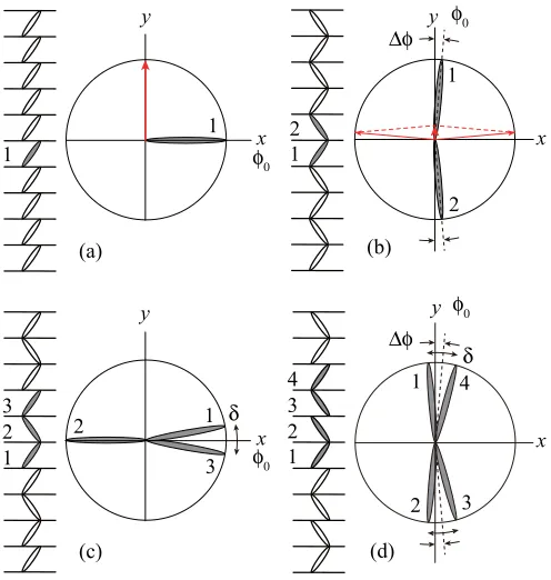
FIG. 1. Electric-field effects in (a) Sm-C∗, (b) Sm-CA∗, (c)
qT =1/3, and (d)qT =1/2. The averaged tilt plane direction is perpendicular to the applied electric field in the (a) ferroelectric and (c) ferrielectric phases. It may become parallel to the electric field in the (b) and (d) antiferroelectric phases; at the same time, the directors in the unit cell may show some small asymmetric change to produce induced polarization in the initial averaged tilt direction, which is observed as the pretransitional effect in the antiferroelectric phases [38–40,48–50]. The electric field is applied along theydirection.
and hence we have cosϕ1=1, i.e.,ϕ1 =0, for ˜E >0. Since ˜
Econtains the product of cpE as in Eq. (18), ˜E >0 means
cp>0 for an electric field applied along theyaxis; the director tilting occurs parallel to thex axis in theϕ1=0 direction as intuitively anticipated from Eqs. (9) and (11) and illustrated in Fig.1(a). In other words,cp>0 corresponds to the positive spontaneous polarization.
In the main antiferroelectric phase Sm-CA∗, it is well known that the director tilting plane tends to be parallel to the electric
field and some small nonplanar (asymmetric) distortion occurs in the planar anticlinic structure as the pretransitional effect [38–40,48–50]. Let us consider that the initial tilt-plane direction isφ0and the distortion angle isφ. Then we can set
ϕ1=φ0−φ, ϕ2=φ0+π+φ. (20) We determine their equilibrium values by minimizing Eq. (17) with respect toφ0andφas follows:
φ0 = ±π
2,
(21)
φ= ± E˜
4{2−T˜+g(cp/cf)(χ cpcf/B)/(1−4g2)}. As illustrated in Fig.1(b), in fact, such a distortion produces a small induced spontaneous polarization along the initial tilt-plane directionφ0= ±π/2; the resulting polarization makes the initial tilt-plane direction align along the applied electric field. Again, cp>0 corresponds to the positive spontaneous polarization consistently.
The structures of all temperature-induced subphases pro-duced by the Emelyanenko-Osipov LRILIs are not planar and possess a certain symmetry that is visible when the structures are viewed along the smectic layer normal. In fact, the tilt directions in different layers are antisymmetric with respect to the middle of the period. This property defines the chirality of the short-pitch deformed helix structures of these subphases as well as a characteristic plane with respect to which the director tilting directions of all smectic layers are arranged symmetrically [36]. In the three-layer field-induced superlattice structure in the temperature region of Sm-CA∗
(qT =1/3), we can check numerically, using Eq. (17) on the assumption of a small deviation from the Ising structure, that the unit cell actually aligns as illustrated in Fig. 1(c). It is also intuitively clear that the averaged tilt-plane direction is arranged perpendicular to the applied electric field.
In this way we can set
ϕ1 =φ0+
δ
2, ϕ2=φ0+π, ϕ3=φ0−
δ
2 (22) and obtain the free energy given in Eq. (17) as a function ofφ0 andδ. By minimizing the free energy with respect toφ0andδ, in fact, we determine these variables as follows:
φ0=0,
δ= − 8(1+2g)(χ cpcf/B)
(1+g−2g2)(6+T˜ +E˜)+(χ c
pcf/B){(1+2g)(cf/cp)+g(cp/cf)}
. (23)
Since ˜Econtains the product ofcpEand the electric field is applied along theyaxis,φ0=0 indicates that the averaged tilt-plane direction is perpendicular to the electric field and the unit cell has positive spontaneous polarization forcp>0. Sinceδandcpcf
have opposite signs, the short-pitch deformed helix is right handed forcpcf <0 and left handed forcpcf >0.
be convenient to set
ϕ1=φ0−φ+
δ
2, ϕ2=φ0+π+φ−
δ
2,
ϕ3=φ0+π+φ+δ
2, ϕ4=φ0+2π−φ−
δ
2,
(24)
whereφ0is the initial average tilt-plane direction at ˜E=0,φthe asymmetric deformation, andδthe distortion angle representing the nonplanar unit-cell structure. Inserting Eq. (24) into Eq. (17), we obtain the free energy as a function ofφ0,φ, andδ. By minimizing the free energy with respect to these variables, we determine the equilibrium values ofφ0,φ, andδas follows:
φ0= ±π
2,
δ= −χ cpcf
B , (25)
φ= ± E˜
2{2−T˜ +2(cf/cp)(χ cpcf/B)+g(cp/cf)(χ cpcf/B)/(1+2g)}.
As shown in Fig.1(d), in fact, such a distortion produces small induced spontaneous polarization along the initial tilt-plane directionφ0= ±π/2; the resulting polarization makes the initial tilt-plane direction align along the applied electric field. Again,
cp>0 corresponds to the positive polarization and the short-pitch distorted helical structure is right handed forcf <0 and left handed forcf >0. Moreover, it is very characteristic thatδis uniquely determined only by the fourth parameter and does not depend on the temperature ˜T and the applied electric field ˜Eas already pointed out in Ref. [36] when ˜E=0.
IV. SEQUENTIAL EMERGENCE OF FIELD-INDUCED SUBPHASES
A. Formulation
As illustrated in Fig. 1, electric-field effects in antiferroelectric superlattice structures are quite different from those in ferroelectric and ferrielectric superlattice structures. In the antiferroelectric case, the applied field may produce some asymmetric distortion in the director arrangements indicating a pretransitional change from antiferroelectric to ferrielectric or ferroelectric [38–40,48–50] and may cause the disappearance of the characteristic plane with respect to which the director tilting directions of all smectic layers were arranged symmetrically when no field was applied. In the ferrielectric case, on the other hand, there is no reason to assume the disappearance of the characteristic plane, although the applied field may destroy the property due to the Emelyanenko-Osipov LRILIs that the tilt directions in different layers are antisymmetrical with respect to the middle of the period; the applied field only interacts with the piezoelectric polarization but not with the flexoelectric polarization as is clear in Eqs. (17) and (18). It is not impertinent to consider that the director tilting directions of all smectic layers are arranged symmetrically with respect to the characteristic plane in all field-induced superlattice structures that emerge on the higher field side of the three-layerqE=1/3 subphase; they must be ferrielectric asqEincreases with the applied field. This characteristic plane can be chosen as thez-xplane and the positive sense of thex
axis is favorable for the director tilting when the electric field is applied along theyaxis andcp>0. The unit cell aligns so that this symmetrical plane becomes perpendicular to the applied electric field.
The applied field effect in the free energy of Eq. (17) is written as
−E˜1
t
t
n=1
cosϕn= −E˜ 1
t
t
n=1
cos(ϕ1+ϕ1,n)
= −E˜1
t
t
n=1 cos
ϕ1+
n−1
k=1
ϕk,k+1
. (26)
Notice that the other terms are the same as given in Eq. (62) of Ref. [36] and are already written in terms ofϕi,i+1≡
ϕi+1−ϕi,wherei=1,2,3, . . . ,t−1. There are four cases in choosingϕ1on the basis of the presence of the characteristic plane.
(i) When thet-layer unit cell under consideration has a layer where the director tilting occurs parallel to the characteristic plane and toward the positive sense of the x axis, we can choose this layer and setϕ1 =0◦.
(ii) Similarly, if the director tilting is toward the negative sense of thex axis, we can setϕ1=180◦.
(iii) When thet-layer unit cell has adjacent layers that are arranged symmetrically with respect to the characteristic plane and their averaged director tilting is along the positive sense of thexaxis, we can setϕ1 = −ϕ1,2/2.
(iv) Similarly, if the director tilting is along the negative sense, we can setϕ1 =180◦−ϕ1,2/2.
In this way, we can fix the orientation of thet-layer unit cell in the applied electric field.
t−1 sets of equations:
2χ cpcf
B
i
n=1 t
m=i+1
fm(1)−n+1cosϕn,m
+χ cpcf
B
i
n=1 t
m=i+1
cp
cffm−n+1+ cf cpf
(2) m−n+1
sinϕn,m
+sin(2ϕi,i+1)+sin
2 t−1
n=1
ϕn,n+1
+T˜
sinϕi,i+1+sin
t−1
n=1
ϕn,n+1
+E˜ −Sδi,1
2 sin
ϕ1,2 2 +
t
n=i+1
1−Sδi,1
2
×sin
−Sϕ1,2
2 +ϕ1,n
=0. (27)
The first four terms on the left-hand side that do not depend on the applied field have already been obtained in Eq. (65) of Ref. [36]. The last term represents the electric-field effect, whereSis
S= 0 for cases (i) and (ii)
1 for cases (iii) and (iv). (28)
Field-induced subphases may be nonplanar, but the actual structure does not deviate largely from the corresponding planar prototype. The anglesϕn,mmay be split into two parts
ϕn,m= m−1
k=n
α(0)k +
m−1
k=n
αk. (29)
Here the angles αk(0)≡ϕk,k(0)+1 may be equal to 0 or π and specify the corresponding planar structure, while the angles
αk≡ϕk,k+1 are relatively small and hence sin(αk)≈
αk.
In this way, we can linearize Eq. (27) with respect toαi: t−1
j=1
ci,jαj =qi. (30)
The right-hand sideqiis defined as
qi = −2
χ cpcf
B
i
n=1 t
m=i+1
fm(1)−n+1cosϕn,m0 , (31)
which is Eq. (68) of Ref. [36]. The left-hand side ci,j is a (t−1)-dimensional matrix defined as for the lower off-diagonal elements (i > j, wherej =1,2, . . . ,t−2 and
i=j +1,j+2, . . . ,t−1)
ci,j(lower)= χ cpcf B
j
n=1 t
m=i+1
cp
cf
fm−n+1+
cf
cp
fm(2)−n+1
cosϕn,m0
+2+T˜cosα0t ±E˜
1−Sδj,1
2
t
n=i+1
cosϕ10,n,(32)
for the diagonal elements (i=j, where i=j =1,2, . . . , t−1)
ci,j(diagonal)= χ cpcf B
i
n=1 t
m=i+1
cp
cffm−n+1+ cf cpf
(2) m−n+1
×cosϕ0n,m+4+T˜cosαi0+cosα0t
±E˜
1−Sδi,1
2
1−Sδj,1
2
×
Sδi,1δj,1+ t
n=i+1 cosϕ1(0),n
, (33)
and for the upper off-diagonal elements (i < j, where i=
1,2, . . . ,t−2 andj =i+1,i+2, . . . ,t−1)
c(upper)i,j = χ cpcf B
i
n=1 t
m=j+1
cp
cffm−n+1+ cf cpf
(2) m−n+1
cosϕ0n,m
+2+T˜cosα0t ±E˜
1−Sδi,1
2
t
n=j+1
cosϕ10,n,
(34) where the plus and minus signs before ˜E represent cases (i) and (iii) and cases (ii) and (vi), respectively. The last terms containing ˜Ein Eqs. (32)–(34) show the effect of an applied electric field, which result from the last term of Eq. (27); the other terms independent of ˜Ehave already been given in Eq. (69) of Ref. [36], although there exist some typographical errors in the original publication [36,51].
B. Numerical calculations
Now let us consider what superlattice structures are stabilized to become field-induced subphases on the higher field side of the three-layerqE=1/3 subphase, particularly in the temperature region where the ferrielectric qT =1/3 subphase stably exists at zero electric field ˜E=0. Given the tilting senseR or Lin a t-layer unit cell by assigning 0 or
π forαk(0)≡ϕk,k(0)+1 in Eq. (29), we can use Eqs. (30)–(34) to uniquely determine the corresponding small deviation angles
αk≡ϕk,k+1 that minimize the dimensionless free energy of Eq. (17). After checking all the possible sequences ofα(0)k , we can expect to obtain an optimal field-induced superlattice structure with thet-layer unit cell. Then, by comparing the free energies of the optimal structures with different-size unit cells with one another, we can determine the field-induced subphase that has the globally minimal free energy at a given applied electric field ˜Efor a particular choice of the other four model parameters.
qE=3/5
15-layer qEn=5
1 2 3 4 5 6 7 8 8’ 9’ 10’ 11’ 12’ 13’ 14’ 15’ 9 10 11 12 13 14 15
qE=3/5
15-layer qEn=4
1 2 3 4 5 6 7 8 8’ 9’ 10’ 11’ 12’ 13’ 14’ 15’ 9 10 11 12 13 14 15
qE=1/2
12-layer qEn=2
1 2 3 4 5 6 7 7’ 8’ 9’ 10’ 11’ 12’ 8 9 10 11 12
qE=5/9
9-layer qEn=3
1 2 3 4 5 6 7 4’ 5’ 6’ 7’ 8’ 9’ 8 9
qE=7/9
9-layer qEn=8
1 2 3 4 5 6 7 8 4’ 5’ 6’ 7’ 8’ 9’ 9
qE=2/3
12-layer qEn=6
1 2 3 4 5 6 7 8 7’ 8’ 9’ 10’ 11’ 12’ 9 10 11 12
qE=5/6
12-layer qEn=9
1 2 3 4 5 6 7 8 7’ 8’ 9’ 10’ 11’ 12’ 9 10 11 12
qE=2/3
6-layer qEn=7
1 2 3 4 5 6 4’ 5’ 6’
qE=1/3
3-layer qEn=1
1 2 3
[image:7.608.110.494.68.371.2]2’ 3’
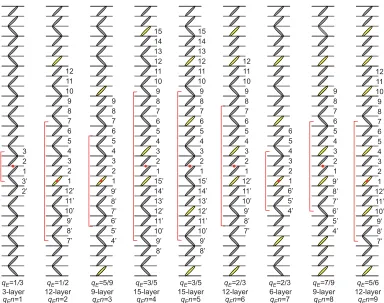
FIG. 2. Nine composite planar superlattice structures used in the free-energy calculation. We only need to calculate the free energy given in Eq. (17) usingαk(0)in Eq. (29) for these nine, if we assume that any field-induced subphase in the temperature region ofqT =1/3 consists of an orderly array of the 3-layer ferrielectric and ferroelectric blocks and that the largest unit cells are of 15-layer periodicity (5 blocks) with simpleqE in lower terms up to 7/9; notice that we have disregardedqE in terms higher than 7/9 (either in numerator or denominator), i.e., 7/15, 11/15, and 13/15. Hereafter we designate these nine asqEn=1, . . . ,9.
the free energy for field-induced superlattice structures with unit cells consisting of up to 15 smectic layers. The actual number of structures becomes much less than 215, because of the periodic boundary conditions and other equivalence properties, but is still more than 1000.
Instead of performing such comprehensive calculations, therefore, here we choose a more intuitive way on the basis of recent experimental findings by microbeam RXRS about the planar structure of the field-induced subphase with a 12-layer unit cell ofqE=2/3. The unit cell can be regarded as a much simpler array of four building blocks, two ferrielectric and two ferroelectric. Each block would be originally the ferrielectric three-layer unit cell of the subphaseqT =1/3 stabilized by the LRILIs, with two consecutive blocks modified to become ferroelectric by an applied electric field. There are three ways to choose the ferrielectric three-layer unit cell ofqT =1/3. In any case, the unit cell contains only one unfavorable L
layer, which the applied electric field may change into the favorable R layer, and the resulting unit cell becomes the unique ferroelectric block; hence the choice of the three-layer unit cell ofqT =1/3 is not essential.
It is not impertinent to generalize the conclusion about the characteristic composite structure of the 12-layer qE=2/3 subphase. Let us consider that any field-induced subphase in the temperature region of qT =1/3 consists of an orderly array of the ferrielectric and ferroelectric blocks and that
the relative ratio of the ferroelectric block becomes larger with increasing applied electric field. We need to consider five different sizes of the composite superlattice structures: The single-block (three-layer) structure hasqE=1/3 and is basically the temperature-induced qT =1/3 subphase. The two-block (six-layer) structure has qE=2/3. There exist two three-block (nine-layer) structures that have qE=5/9 and 7/9, respectively. Similarly there are three four-block (12-layer) structures that have qE=1/2, 2/3, and 5/6, respectively. In the case of five-block (15-layer) structures,
qE=7/15, 2/3, 11/15, and 13/15, which are not fractions in lower terms, except forqE=2/3. We have a disregard for these fractions in higher terms such as 7/15, 11/15, and 13/15 by simply assuming that unit cells with qE’s in lower terms must be observed easily. This way of simplification extremely reduces the number of planar superlattice structures to be examined when we search for a field-induced subphase. We only need to calculate the free energy given in Eq. (17) using
α(0)k in Eq. (29) for the planar superlattice structures shown in Fig.2as well as for the Sm-C∗phase. Hereafter we designate these nine asqEn=1, . . . ,9.
Actual calculations were performed for parameter values used in the classical paper [36,51], χ cpcf/B = −0.12 and
FIG. 3. Reproducedg- ˜T phase diagram with parameter values of
χ cpcf/B= −0.12 andcf/cp= −1.0 [36,51], and nine chosen points in red for studying the electric field effect: ˜T = −0.24,−0.21, and −0.18 atg=0.1; ˜T = −0.21,−0.16, and −0.09 at g=0.2; and
˜
T = −0.09,−0.02, and 0.05 atg=0.3.
free energies for g=0.1 and ˜T = −0.18; similar results are obtained for the other g and ˜T values investigated. We begin with the limits of our analysis. Apparently, the direct field-induced transition occurs fromqEn=1 to Sm-C∗ and no sequential transitions among field-induced subphases are observed. This must be caused by the fact that the free energy of the actual Sm-C∗phase is not appropriately given by Eq. (19). All the subphases are not planar and have the microscopic short-pitch highly distorted helical structures, whereas the
Sm-C∗ phase is considered to be perfectly planar. Since the frustration actually occurs among the Sm-CA∗, Sm-C∗, and Sm-Aphases [8,27], the discrete flexoelectric effect produces the helical structure even in the Sm-C∗phase. The free energy of the Sm-C∗ phase calculated by Eq. (19) must be lower than that of the actual field-induced unwound Sm-C∗ phase and hence the direct field-induced transition fromqEn=1 to Sm-C∗ is always observed as illustrated in TableI. A more elaborate treatment should be made by taking into account the three-phase frustration among the Sm-CA∗, Sm-C∗, and Sm-A
phases as well as the temperature-dependent tilt angleθ. The direct field-induced transition fromqEn=1 toqEn=9, the structure of which is quite similar to Sm-C∗, is also observed and invades the stability range of the other subphases that may participate in the sequential field-induced transitions. We have, therefore, a disregard forqEn=9 (qE=5/6) as well as Sm-C∗in the following.
Among the remaining eight field-induced superlattice struc-turesqEn=1, . . . ,8, the most stableqEn=1 is basically the temperature-induced qT =1/3 subphase at ˜E=0; it exists in a wide field range up to ˜E=0.676 and then makes the field-induced transition to qEn=4 at ˜E=0.677. The field-induced transition fromqEn=4 toqEn=6 is observed at ˜E=0.681. The qEn=6 field-induced subphase has the 12-layer unit cell ofqE=2/3 and exists as the second stable field-induced subphase for all theg values and temperatures investigated. The third stable field-induced subphase may be
qEn=4 with the 15-layer unit cell of qE=3/5 in all the temperatures investigated for g=0.1 and 0.2. Its stability range of ˜Eis narrower ing=0.2 than in 0.1; it is not stabilized for g=0.3. Another field-induced transition from qEn=6 toqEn=8 may occur at 0.684. TheqEn=8 field-induced subphase has the nine-layer unit cell of qE=7/9. Since
TABLE I. Calculated dimensionless free-energy densities ˜Ft for nine possible superlattice structures shown in Fig.2as well as Sm-C∗at ˜
T = −0.18 forg=0.1. Aside fromqEn=9 and Sm-C∗,qEn=1 has the smallest ˜Ft up to ˜E=0.676, but firstqEn=4, secondqEn=6, and thenqEn=8 stabilize at ˜E=0.677, 0.681, and 0.684, respectively, as indicated by the corresponding ˜Ft’s shown in boldface. Notice, however, that the direct transition fromqEn=1 toqEn=9 always occurs when it is included. For details, see the text.
qEn=1 qEn=2 qEn=3 qEn=4 qEn=5 qEn=6 qEn=7 qEn=8 qEn=9 Sm-C∗
qE=1/3 qE=1/2 qE=5/9 qE =3/5 qE =3/5 qE=2/3 qE=2/3 qE=7/9 qE=5/6 qE =1 ˜
[image:8.608.52.557.518.754.2]2 3 4 5 6
7 8 9
9’
8’
10’
11’
12’
13’
15’
14’ 10 11 12 13 15 14
1
1
(-3.0 o ) (3.9 o
) (-6.2 o
) (0 o
) (6.2 o
) (-3.9 o
) (-9.6 o
) (-3.6 o
) (-1.9 o
) (-0.6 o
)
(3.0 o )
1.9 o 0.6 o 3.6 o 9.6 o 183.0 o 356.2 o 366.2 o 540.0 o 713.8 o 723.8 o 896.9 o 1070.4 o 1076.3 o 1078.0 o 1079.4 o
6
7
123 4
5 1011
9
8 12
1 2 3 4 5 6
7 8
7’
8’
9’
10’
11’
12’
9 10 11 12
1.8 o 0.5 o 3.3 o 9.0 o 182.1 o 355.1 o 364.9 o 537.9711.0 o o 716.7 o 718.2 o 719.5 o
(-2.1 o ) (4.9 o
) (-9.0 o
) (-3.3 o
) (-1.8 o
) (-0.5 o
)
(-4.9 o ) (2.1 o
) 15-layer
qE=3/5
qEn=3
12-layer
qE=2/3
qEn=5
1 4
5 623
7 8
9
10 11
[image:9.608.118.489.71.398.2]121314 15
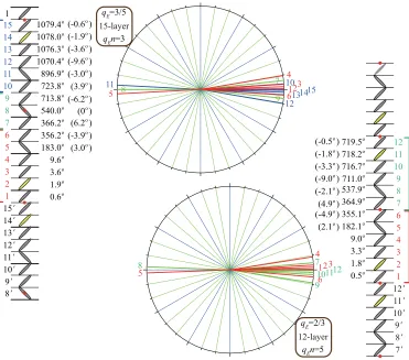
FIG. 4. CalculatedϕiforqEn=4 at ˜E=0.573 and forqEn=6 at ˜E=0.574. Other parameters areg=0.2,T˜ = −0.09,χ cpcf/B= −0.12, andcp/cf= −1.0. The relevant dimensionless free energies are−1.5113 for qEn=1 at ˜E=0.572,−1.51166 for qEn=4 at
˜
E=0.573, and−1.51228 forqEn=6 at ˜E=0.574. The electric field is applied along theyaxis and it is assumed thatcp>0 and hence that the spontaneous polarization is positive and the microscopic short-pitch distorted helix is right handed. The tilt directions in different layers are symmetrical with respect to the middle of the period indicated by closed red circles; this property defines the chirality of these subphases.
qEn=8 is rather close to the Sm-C∗ phase and its qE is hardly regarded as a fraction in lower terms, it may not exist as a single independent stable subphase; it may overlap with other similar field-induced subphases. The remainingqEn=2, 3, 5, and 7 are not stabilized at all and hence do not exist as the field-induced subphases.
Figure4shows the microscopic short-pitch helical struc-tures of theqEn=4 and 6 subphases with the 15-layer and 12-layer unit cells, respectively. The calculations were made in the linearized approximation explained in Sec.IV B. The
qEn=4 helix makes three rotations in the 15-layer unit cell, whereas theqEn=6 helix makes two rotations in the 12-layer unit cell. The director tilting directions of all smectic layers are arranged symmetrically with respect to thez-x plane. As we expected, the deviation from the planar structures is small in both subphases. At the same time, we notice that the deviation is slightly larger in the qEn=4 helix than in theqEn=6 helix, when we compare both helices carefully. As a measure of the deviationD, we calculated
D= 1
t
t
i=1
|sinφi| (35)
and actually obtainedD=0.067 and 0.063 for theqEn=4 and 6 helices, respectively.
V. DISCUSSION
The calculated results are entirely consistent with the recent microbeam RXRS data [33]. The experiments were performed using a slightly unusual compound that has chiral centers in both terminal chains and a bromine atom in its central core part; the chemical structure is given in Fig. 5. The phase sequence is, however, quite ordinary [52]: Sm-C∗A–1/3– 1/2–Sm-C∗–Sm-Cα∗–Sm-A–Iso. The prototypal subphases
qT =1/3 and 1/2 emerge between the main phases Sm-CA∗ and Sm-C∗; hence it is legitimate to consider that the subphases are produced by the frustration between antiferroelectric Sm-CA∗ and ferroelectric Sm-C∗phases and to use the approx-imation that the tilt angle is relatively large, spatially uniform, and temperature independent. As explained in Sec.II, in fact, we have calculated the free energy based on this approximation
C6H13CHOC
O
O
C C6H13
* *
CH3
CH3
CH O
O C O O
OC Br
relying on the LRILIs introduced by Emelyanenko and Osipov [36], disregarding that the actual frustration occurs among the three main phases Sm-CA∗, Sm-C∗, and Sm-A [8]. Further-more, the calculations have been performed for field-induced superlattice structures that may emerge on the higher field side of the three-layer qE=1/3 subphase. The microbeam RXRS data were taken in three different temperature regions of Sm-CA∗ (140◦C),qT =1/3 (144◦C), andqT =1/2 (145.1◦C and 146◦C); all of them show nearly the same tendency that field-induced superlattice subphases may emerge on the higher field side of the three-layerqE=1/3 subphase, except for the data at 146◦C; hence we choose the most elaborate data at 140◦C shown in Fig. 7 of Ref. [33] and compare them with the calculated results in the following.
The experimental results indicate that the three-layer peri-odicity prevails in a wide electric field range and that not only the 12-layer but also the 15-layer periodicity is inseparably observed as a spotty pattern in a narrow electric field region, above which the spotty pattern changes into a diffuse streak pattern just before the field-induced transition to the Sm-C∗
phase occurs. The three-layer periodicity must basically result from the qEn=1 field-induced superlattice structure, i.e., the three-layer unit cell of the temperature-inducedqT =1/3 subphase together with its behavior in an applied electric field described in Sec. III. As exemplified in Table I, the stability range ofqEn=1 is pretty wide. It stably exists up to ˜E=0.676 and then three field-induced transitions stabilize
qEn=4 at ˜E=0.677, qEn=6 at ˜E=0.681, and qEn= 8 at ˜E=0.684 sequentially. The field-induced subphases
qEn=4 and 6 have a 15-layer unit cell of qE=3/5 and a 12-layer unit cell ofqE=2/3, respectively; their stability ranges are very narrow. As explained in Sec.IV B,qEn=8 is rather close to Sm-C∗ and may not be observed as a single independent subphase due to overlapping with other subphases.
In this way, the observed 15-layer and 12-layer periodic spotty patterns naturally correlate with the field-induced subphases qEn=4 and 6 in Table I, respectively; the ob-served diffuse streak pattern may result from some over-lapped field-induced subphases including qEn=8, which have large unit cells and complex qE’s in higher terms and become inevitably disordered by a number of factors. The experimentally confirmed fact that the nine-layer and six-layer periodicities were not observed correlates with the calculated results that qEn=3 and 7 are not stabilized in Table I. Experimentally, the microbeam RXRS could not confirm the existence ofqEn=2 consisting of four three-layer blocks, three ferrielectric and one ferroelectric, which produce almost the same satellite peak intensity distribution (strong
m/3-order satellites) as the original three-layer qE=1/3 phase, qEn=1. The calculated results illustrated in Table Ishow thatqEn=2, the 12-layer field-induced superlattice structure ofqE=1/2, does not stably exist as a field-induced subphase.
Now let us investigate the satellite peak intensity dis-tribution patterns further. By using the Osipov-Gorkunov formula [53] to obtain RXRS intensities for all possible planar structures with 12-layer periodicity, as illustrated in Fig. 8 of Ref. [33], it was concluded that only two planar structures with qE=2/3 and 1/6 were consistent with the
experi-mentally observed intensity distribution. Since the 12-layer structure was produced by the field-induced transition from the three-layer structure withqE=1/3 in all the temperatures investigated, except for 146◦C, the 12-layer structure with
qE=1/6 was considered improbable [33]. Notice that the remaining 12-layer structure withqE=2/3 is exactly the same as the most stable calculatedqEn=6 with the 12-layer unit cell shown in Fig.2.
Regarding the 15-layer unit cell, the RXRS data given in Fig. 7 of Ref. [33] clearly indicate the emergence of a field-induced subphase with a 15-layer unit cell but could not determine its planar structure because the signal intensity is weak. However, the RXRS data are consistent with the calculated result that an applied electric field may stabilize
qEn=4 but notqEn=5. The Osipov-Gorkunov formula [53] indicates that the RXRS intensities of 4/15 and 6/15 are about 1/4 of the intensity of 5/15 inqEn=4, whereas the intensities are about 1/24 in qEn=5. As clearly shown in Fig. 7 of Ref. [33], the RXRS intensities of 4/15 and 6/15 are closer to 1/4 and hence we can conclude that the applied electric field stabilizesqEn=4.
Figure4shows that the deviation from the planar structure in the qEn=6 subphase is slightly smaller than that in the
qEn=4 subphase and in fact the measure of deviation defined by Eq. (35) is smaller in the qEn=6 subphase than that in the qEn=4 subphase. Suppose we observe the electric-field-induced birefringence (EFIB) at 144◦C by increasing the applied electric field: The EFIB first rises sharply due to the unwinding of the macroscopic long-pitch helical structure. When the field-induced qEn=1 subphase prevails, EFIB stays almost constant in a wide applied electric-field range. Just before the field-induced transition to the unwound Sm-C∗
phase occurs, EFIB once decreases slightly and then increases again whenqEn=4 and 6 emerge consecutively in a narrow electric-field range. In the electric-field–temperature E-T
phase diagram, characteristic sigmoid-shaped birefringence contours are expected to be observed in the neighborhood of subsequent decreasing and increasing. Although in different materials Sandhyaet al.actually observed the sigmoid-shaped contours in the MHPOCBC-MHPOOCBC binary mixture system as given in Figs.2(i)–2(k)of Ref. [4]. They referred to the emergence of several field-induced subphases, but did not suggest such large unit cells of 12- and 15-layer periodicity shown in Fig.4. Their microscopic short-pitch distorted helical structures have not yet been verified experimentally by using polarized RXRS experiments.
the deviation from the planar structure inqEn=4 is larger than that inqEn=6; EFIB may decrease slightly and then increase again as actually observed, although in different materials [4]. A weak point of this simplest way of treating lies in the fact that the Sm-C∗ phase is considered to be perfectly planar in the prototypal quasimolecular model. Actually, however, the discrete flexoelectric effect produces the helical structure even in the Sm-C∗ phase, since the frustration occurs among the Sm-C∗A, Sm-C∗, and Sm-A phases. A more elaborate treatment should be made by taking into account the three-phase frustration as well as the temperature-dependent tilt angle θ as actually made at ˜E=0 preliminarily [7–9,27]. This treatment may also explain the characteristic evolution
of the subphase emergence observed in several binary mixture systems [2,4].
ACKNOWLEDGMENTS
This work was partly supported by an Ireland-Japan Interna-tional Strategic Cooperation Award and 13/US/I2866 Science Foundation Ireland grant as part of the USA-Ireland Research and Development Partnership program jointly administered with the United States National Science Foundation under Grant No. NSF-DMR-1410649. The authors thank Prof. M. A. Osipov of University of Strathclyde, Glasgow, Scotland for discussions.
[1] T. Isozaki, T. Fujikawa, H. Takezoe, A. Fukuda, T. Hagiwara, Y. Suzuki, and I. Kawamura,Phys. Rev. B48,13439(1993). [2] A. Fukuda, Y. Takanishi, T. Isozaki, K. Ishikawa, and H.
Takezoe,J. Mater. Chem.4,997(1994).
[3] A. D. L. Chandani, N. M. Shtykov, V. P. Panov, A. V. Emelyanenko, A. Fukuda, and J. K. Vij,Phys. Rev. E72,041705 (2005).
[4] K. L. Sandhya, J. K. Vij, A. Fukuda, and A. V. Emelyanenko, Liq. Cryst.36,1101(2009).
[5] J. Prost and R. Bruinsma,Ferroelectrics148,25(1993). [6] R. Bruinsma and J. Prost,J. Phys. (France) II4,1209(1994). [7] M. A. Osipov and A. Fukuda,Phys. Rev. E62,3724(2000). [8] N. M. Shtykov, A. D. L. Chandani, A. V. Emelyanenko, A.
Fukuda, and J. K. Vij,Phys. Rev. E71,021711(2005). [9] A. V. Emelyanenko and K. Ishikawa,Soft Matter9,3497(2013). [10] C. C. Huang, S. Wang, L. Pan, Z. Q. Liu, B. K. McCoy, Y. Sasaki, K. Ema, P. Barois, and R. Pindak,Liq. Cryst. Rev.3,58 (2015).
[11] P. Mach, R. Pindak, A.-M. Levelut, P. Barois, H. T. Nguyen, C. C. Huang, and L. Furenlid,Phys. Rev. Lett.81,1015(1998). [12] P. Mach, R. Pindak, A.-M. Levelut, P. Barois, H. T. Nguyen, H.
Baltes, M. Hird, K. Toyne, A. Seed, J. W. Goodby, C. C. Huang, and L. Furenlid,Phys. Rev. E60,6793(1999).
[13] A.-M. Levelut and B. Pansu,Phys. Rev. E60,6803(1999). [14] T. Akizuki, K. Miyachi, Y. Takanishi, K. Ishikawa, H. Takezoe,
and A. Fukuda,Jpn. J. Appl. Phys.38,4832(1999).
[15] P. M. Johnson, D. A. Olson, S. Pankratz, T. Nguyen, J. Goodby, M. Hird, and C. C. Huang,Phys. Rev. Lett.84,4870 (2000).
[16] A. Cady, J. A. Pitney, R. Pindak, L. S. Matkin, S. J. Watson, H. F. Gleeson, P. Cluzeau, P. Barois, A.-M. Levelut, W. Caliebe, J. W. Goodby, M. Hird, and C. C. Huang,Phys. Rev. E64,050702(R) (2001).
[17] I. Musevic and M. Skarabot,Phys. Rev. E64,051706(2001). [18] N. M. Shtykov, J. K. Vij, and H. T. Nguyen,Phys. Rev. E63,
051708(2001).
[19] N. M. Shtykov, J. K. Vij, R. A. Lewis, M. Hird, and J. W. Goodby,Liq. Cryst.28,1699(2001).
[20] N. W. Roberts, S. Jaradat, L. S. Hirst, M. S. Thurlow, Y. Wang, S. T. Wang, Z. Q. Liu, C. C. Huang, J. Bai, R. Pindak, and H. F. Gleeson,Europhys. Lett.72,976(2005).
[21] P. Fernandes, P. Barois, E. Grelet, F. Nallet, J. W. Goodby, M. Hird, and J.-S. Micha,Eur. Phys. J. E20,81(2006).
[22] P. D. Brimicombe, N. W. Roberts, S. Jaradat, C. Southern, S.-T. Wang, C.-C. Huang, E. DiMasi, R. Pindak, and H. F. Gleeson, Eur. Phys. J. E23,281(2007).
[23] S. Wang, L. D. Pan, R. Pindak, Z. Q. Liu, H. T. Nguyen, and C. C. Huang,Phys. Rev. Lett.104,027801(2010).
[24] V. P. Panov, N. M. Shtykov, A. Fukuda, J. K. Vij, Y. Suzuki, R. A. Lewis, M. Hird, and J. W. Goodby, Phys. Rev. E69, 060701(R) (2004).
[25] A. D. L. Chandani, A. Fukuda, S. Kumar, and J. K. Vij,Liq. Cryst.38,663(2011).
[26] Y. Takanishi, I. Nishiyama, J. Yamamoto, Y. Ohtsuka, and A. Iida,Phys. Rev. E87,050503(R) (2013).
[27] K. L. Sandhya, A. D. L. Chandani, A. Fukuda, S. Kumar, and J. K. Vij,Phys. Rev. E87,062506(2013).
[28] K. Hiraoka, Y. Takanishi, K. Skarp, H. Takezoe, and A. Fukuda, Jpn. J. Appl. Phys.30,L1819(1991).
[29] T. Isozaki, T. Fujikawa, H. Takezoe, A. Fukuda, T. Hagiwara, Y. Suzuki, and I. Kawamura,Jpn. J. Appl. Phys.31,L1435(1992). [30] N. M. Shtykov, J. K. Vij, R. A. Lewis, M. Hird, and J. W.
Goodby,Phys. Rev. E62,2279(2000).
[31] S. Jaradat, P. D. Brimicombe, C. Southern, S. D. Siemianowski, E. DiMasi, M. Osipov, R. Pindak, and H. F. Gleeson,Phys. Rev. E77,010701(R) (2008).
[32] K. L. Sandhya, A. Fukuda, and J. K. Vij,Mol. Cryst. Liq. Cryst.
511,36/[1506](2009).
[33] A. Iida, I. Nishiyama, and Y. Takanishi,Phys. Rev. E89,032503 (2014).
[34] P. V. Dolganov, V. M. Zhilin, V. K. Dolganov, and E. I. Kats, Phys. Rev. E83,061705(2011).
[35] P. V. Dolganov and E. I. Kats,Liq. Cryst. Rev.1,127(2013). [36] A. V. Emelyanenko and M. A. Osipov,Phys. Rev. E68,051703
(2003).
[37] A. V. Emelyanenko and M. A. Osipov,Ferroelectrics309,13 (2004).
[38] T. Qian and P. L. Taylor,Phys. Rev. E60,2978(1999). [39] L. A. Parry-Jones and S. J. Elston,Phys. Rev. E63,050701(R)
(2001).
[40] L. A. Parry-Jones and S. J. Elston,Appl. Phys. Lett.79,2097 (2001).
[41] J.-K. Song, A. Fukuda, and J. K. Vij, Phys. Rev. Lett.101, 097801(2008).
[43] Y. Suzuki, G.-P. Chen, U. Manna, J. K. Vij, and A. Fukuda, Appl. Phys. Express2,071403(2009).
[44] P. V. Dolganov, V. M. Zhilin, V. K. Dolganov, and E. I. Kats, Phys. Rev. E86,020701(R) (2012).
[45] A. V. Emelyanenko,Eur. Phys. J. E28,441(2009). [46] A. V. Emelyanenko,Phys. Rev. E82,031710(2010). [47] A. V. Emelyanenko,Ferroelectrics495,129(2016).
[48] M. Johno, K. Itoh, J. Lee, Y. Ouchi, H. Takezoe, A. Fukuda, and T. Kitazume,Jpn. J. Appl. Phys.29,L107(1990).
[49] K. Hiraoka, H. Takezoe, and A. Fukuda,Ferroelectrics147,13 (1993).
[50] J.-K. Song, A. Fukuda, and J. K. Vij, Appl. Phys. Lett. 93, 142903(2008).
[51] A. Fukuda,Mol. Cryst. Liq. Cryst.610,1(2015).
[52] Y. Takanishi, I. Nishiyama, J. Yamamoto, Y. Ohtsuka, and A. Iida,J. Mater. Chem.21,4465(2011).
![FIG. 3. Reproduced gT−in red for studying the electric field effect: χc˜ = −0p.- T˜ phase diagram with parameter values ofcf/B = −0.12 and cf/cp = −1.0 [36,51], and nine chosen pointsT˜ = −0.24, −0.21, and18 at g = 0.1; T˜ = −0.21, −0.16, and −0.09 at g = 0.2; and0.09, −0.02, and 0.05 at g = 0.3.](https://thumb-us.123doks.com/thumbv2/123dok_us/1015576.616472/8.608.52.557.518.754/reproduced-studying-electric-diagram-parameter-values-chosen-pointst.webp)