r
$3.95
April-May 1987
Software A
lications
Swimming In The Relational Lake . ... . 14
Designing relational databases.
Expert
System. ...
.
...
.
...
.
....
22
Gary designs an expert system with Prolog.
Nasty
Software ...
..
..
.
.. 82
A plague of new programs in the public domain.
Hardware Applications
-
Controlling The Real World ...
6
Build an 8-channel temperature scanner.
The Bleeping PC ...
.
....
.
...
.
... 30
Strange noises from clonal counters.
Who's Making Great Hard Drives ... 44
Read before you purchase your next hard drive.
Changing the Picture ...
~... 86
-.j"
0
p~~ :~::.J ~::.:~ UJ III <..: ):1
>:~. :::1 ill t:) i:'/ r:J ::::
I:J ... j'TJ
::1:) :".~~ ~ t 0.1 •
: L> t~:J ~.;~: t "':1 :!:~: t:'l
:1.'.,
I :.~ I
it.
l.n
:u
1"1
00 00
/'f)
'"
0I'--.j" -.j"
I'-0
$3.95
April-May 1987
No. 35
Software
A~lications
Swimming In The Relational Lake ... 14
Designing relational databases.
. Expert System ...
22
Gary designs an expert system with Prolog.
Nasty Software ... 82
A plague of new programs in the public domain.
Hardware Applications
Controlling The Real World ... 6
Build an 8-channel temperature scanner.
The Bleeping PC ... 30
Strange noises from clonal counters.
Who's Making Great Hard Orives ... 44
Read before you purchase your next hard drive.
Changing the Picture ...
; ... 86
:HER'PRODUCTS
, '. ". :", ' ' . ! i - ~.. " , ,"·{lVIath:Copn)cessor for X16B
,,'rheX16,B087;Math Coprocessor runs at full CPU speed. That's i;;'F::':10Ml7zofnumber smashing power! The Math Coprocessor on the , : ' , ""'AT;only'runsat 2/3 of the CPU clock.
~:,~SqSIPort
Option,for'X16B
:.",'" '"FuJISCSI port using the 5380. Software built into ROM BIOS for the '.oMT13100 hard disk controller achieves a 1 to 1 sector interleave.
,:" ::"";"FOlJR,,',MEGGER
Runri'ing out of spreadsheet room? Need something faster than a ,~arq disk for those long compiles? The Four Megger ,is the answer.
,T~e Four Megger meets the Lotus/lntellMicrosoft expanded
m'emory specifications and works in all PC andXT computers. The Four Megger also works in AT computers, as expanded memory only.
2S1P
We found ourselves lacking for a flexible two serial ports and parallel printer port. So we designed the 2S1P (which is short for 2 Serial, 1 Parallel) board. It's small, inexpensive and made here, of course!
,Memories
The PC .Tech Memories board allows additlonal ROM or static RAM , to be put in a PC, XT, AT, X168 or compatible. We designed it for
diagnostics. You can use it for booting without disks, scraping your windshield or whatever!
P.O. Box 128
904 North 6th Street
Lake City, MN 55041
(612) 345·4555
'; ' ..
"oa~r~;
';the'highest' ',',"" "
:~'t{i\~perf,orn,ance~Uld "integ'ratio~'bf
<'
:,>
anY,pC/XTcompatible.With its,
'tOM
Hz,
,zero wait state
operation it 'walks away from AT ,
compatibles as well. On board is
one megabyte of DRAM, a real
time clock, floppy disk
controller, and optional one or
two serial ports, SCSI port and
8087.
The PC Tech SmartBIOS
provides PC compatability with
ease of use. We wrote it and we
support it!
PRICES!
X16B I 1 Meg I RTC .... $600.00
8 MHz version ... $540.00
SCSI option ... $25.00
Serial ports (2) .
~... $38.75
8087-1/82188 ...
$340.00
8087-2/82~88
. ...
$260.00
Four Megger' ... $850.00
2S 1 P ... $99.00
Memories ... $95.00
Systems:
The Box ... $799.00
Mono System ... $1,099.00
EGA System ... $1,849.00
Call for system configuration details. PC Tech also sells hard drives and controllers, video boards and mon itors, etc.
APPRENTICE
PACKAGE
$99
• Separate Compilationwfinter-module typechecking • Native Code Generation • Large Memory Model Support • Most Powerful Runtime Debugger • Comprehensive Module Library • Maintainability
• Translator from Turbo and ANSI Pascal
WIN AFREE·TRIPTO
Switz¢rland
Return your Modula-2 Registration Card or a reasonable facsimile~ posttriarkedbetween March 1, 1987 and May 31;1987tobeinc1uded in a once-only drawing! . . Grand PriZe: One week excursion for 2 in .Zurich, Switzerlandincluding a guided tour of
ETH, the University where M6dula-2 was created by Niklaus Wirth. European custom-ers may substitute a trip to Silicon Valley, . California.
Second and Third Prizes: LOGITECH C7 Mouse or WGITECH Bus MoUse with Paint
& Draw software - a $219 value, absolutely
free! .
. *Write to Logitech, Inc. for a registration card facsimile. . ' "
_ APPRENTICE PACKAGE $99
Everything you need to begin producing reliable maintainable Modula-2 code. Includes the Compiler with 8087 support, integrated Editor, Linker, and BCD Module. We're also including FREE our Turbo Pascal to Modula-2 Translator!
_ WIZARDS'PACKAGE $199
This package contains our Plus Compiler-for professional programmers or for those who just want the best. The Plus Compiler with Integrated Editor requires 512K and takes advantage of the larger memory to increase compilation speed by 50%. Our Turbo Pascal to Modula-2 Translator is also includ-ed at no extra charge.
_ MAGIC TOOLKIT $99
We've put our most powerful development tools into one amazing Toolkit for use with either the Apprentice or Wizards' packages. Highlighted by our Runtime Debugger, the finest debugging tool avail-able anywhere, the Toolkit also includes our Post Mortem Debugger, Disassembler, Cross Reference utility and Version which keeps track of different versions of one program. Our MAKE Utility figures out module dependencies and automatically selects those affected by code changes to minimize recom-pilation and relinking. We also provide source code of our major library modules for you to customize'-or just play with.
WINDOW PACKAGE $49
Now you can build true windowing into your Modula-2 code. Features virtual screens, color sup-port, overlapping windows and a variety of borders.
ROM PACKAGE AND CROSS
RUN TIME DEBUGGER $299
fur those who want to produce rommable code. You can even debug code running in ROM from your Pc.
Turbo Pascal is a registered trademark of Borland International.
WIZARDS'
PACKAGE
$199
Call for information about our VAX/VMS version, Site License, University
Discounts, Dealer & Distributor pricing.
To place an order call toll-free:
800-231-7717
In California:
800-552-8885
••••••••••••••••••••••••••
YES
'
I want the spellbinding power • of LOGITECH Modula-2!o
Apprentice Package $99o
Wizards' Package $199o
Magic Toolkit $99o
Window Package $49o
ROM PkglCross RTD $299Add $6.50 for shipping and handling. Calif. residents add applicable sales tax. Prices valid in U.S. only.
Total Enclosed $ _ _ _ _
o
VISA 0 MasterCard 0 Check EnclosedCard Number Expiration Date
Signature
Name
Address
City State
Zip Phone
~LOGITECH
WGITECH, Inc.
805 Veterans Blvd. Redwood City, CA 94063 Tel: 415-365-9852
In Europe: WGITECH SA, Switzerland Tel: 41-21-879656 • Telex 458 217 Tech Ch
In Italy: Tel: 39-2-215-5622
AROUND THE BEND
Sympathy
Wanted
By
David Thompson
I'm bummed, burned-out, through with the humor and high jinks. Hilarity stinks. If. you want fun, make your own.
Margret and I have been working day and night trying to desktop Micro C. We've created style sheets, added commands to articles, formatted listings, and generally en-joyed our new-found power. Everything we wanted to do (reverse video, lines, captions, illustrations ... ) we did. With Ventura Publisher.
Once we had our style sheets done, articles finished, boxes drawn, all we had to do was run Ventura's PostScript output through a Linotronic RIP and we'd have a magazine. So three weeks ago I packed up Sandy, the kids, and a system and headed for the nearest Linotronic.
That was 108 long distance calls (covering eight states), seven express packages (two lost), and six attempts at modem communications ago.
We still haven't found anyone (including Adobe, Ven-tura, Xerox, or Linotype) who can help us dump a small PostScript file through a Linotype RIP (Raster Image Processor or Rest In Peace, you take your pick).
We've badgered, berated, beleaguered, and bullied all 6 typesetting houses in the northwest that have PostScript RIPs. They were all certain they could do it. ("Hey Mur-phy, over here. Easy pickins.")
Everyone was surprised. All but Xerox (Xerox was un-reachable) had suggestions:
"Remove the special headers we add to PostScript files when they're destined for the Apple Laserwriter," was the suggestion from both Linotype and Ventura. After deleting 194 lines of illegible hex the file still wouldn't run. "You must be using more than 3 fonts. Of course, the internal fonts don't count." We were only using three fonts, internal or otherwise.
Some of the houses only had MACs. I should have skipped them altogether.
"Our MAC is automatically stripping carriage returns as your file comes in off the modem, and I'm getting little boxes prepended to each line. That must be the problem." The small boxes turned out to be linefeeds. Not a problem. But the RIP still couldn't output the file.
"Let's see, we take this file and output it to the RIP through the MAC's PostScript interpreter. That's always worked with Apple files."
Come On! It's already a PostScript file; if you PostScript it again it's not going to work.
April-May 1987
Issue No. 35
Features
6
14
20
22
28
30
32
44
48
54
Bruce Eckel
Controlling
The Real
World
Bruce builds an 8-channel temperature scanner with support software in Turbo Pascal.
Sandy Brabandt
+5V RESISTOR
NETWORK
RN2
Swimming In The Relational Lake
This is the first episode in the dramatic tale of Dr. Dobbs (veterinarian, not dentist) and the data files.
Larry Fogg
The Micro C Half-Fast Computer
Larry tried to stop his system (teach it to one-step) but he quit half way. A fun look at a serious subject.
Gary Entsminger
Expert System
Curious about Prolog? Want to do something with it? Follow along as Gary begins creating an expert system.
Don McClimans
The Rochester Data Dynatyper
Two issues ago I asked folks to send in examples of good ideas that turned into dogs. This is one that was loaded with fleas.
Larry Fogg
A Bleeping PC
The 8253 is a very smart counter. Unfortunately, it also generates the PC's beeps. Larry pokes about in the 8253 and the result is weird.
Alexander Wright
S-100 Bargains
New card-cages for old, new card-cages for old. Actually, it's new cages for cheap. And you can use a standard PC power supply.
David Thompson
Who's Making Great Hard Drives
This is opinion, hearsay, and surmise at their second best. (Second only to "Nasty Software. ")
Tracey Anthony & Laura Logan
SOG VI, The Micro C Technical
Forum
If you haven't attended a Semi-Official Get-together
(SOG) then you've missed a technical marathon that's unmatched, anywhere.
Margret Rosenberg
The 68000
Joe Bartel's cheap 68000 project has brought a lot of Motorola fans out of the woodwork.
60
72
82
86
CONTENTS
Russ Eberhart
Learn Assembly language
8088 assembly language isn't easy. Russ looks at books that'll help you register all those segments.
Bruce Eckel
Concise Computer Electronics
Bruce covers beginning hardware procedure for beginning hardware builders.
David Thompson
Nasty Software
This piece on Trojan programs may be the best read article in this issue. However, "Don't Panic!"
Dean Klein
Changing the Picture
The TI 34010 is a 32-bit micro-processor designed to handle graphics.
Columns
26
36
42
58
63
68
78
84
On Your Own
Cecil Stump goes over the problems he's faced selling his Express editor.
Kaypro
Mark Boyd bites into two flavors of Modula-2 for CP/M. His review of the Turbo and FTL Modulas fills a real cavity.
In the Public Domain
Steve steps down as librarian for SIG/M and then sends a check to a shareware· author!
86 World
Laine takes us on a visit of old Constantinople and high density drives.
Culture Corner Pascal Procedures
Learning Modula-2? Learning Pascal? John goes back over the basics in both languages. (Habla Usted Pascal?)
C'ing Clearly
Ron Miller tackles TSR (terminate but stay resident) routines in C.
Techtips
Future Tense
By Gary Entsminger
66
96
Tidbits
Gary looks at Taskview's new COMMAND and Micro C's new PROLOG contest.
The Last Page
Gary demos DEMO.
Ground Water?
I read Larry's comment about ground water (issue #34, "A Quiet Morning At Micro C") to my spouse, who immediately replied, "It's easy to grind water. First you dehydrate it.. .. "
Also, even though it's not docu-mented, you can use command line ar-guments with the MIX-C compiler. You must use a pointer to an array, and remember that the I\filename is the first (number zero) argument.
Gil Josephson Square Dance Caller 719 S. Belgrade Rd. Silver Spring, MD 20902
MIDI Info
This is in response to Thatcher Deane's letter in issue #33. The MIDI bus information is available from:
International MIDI Association 12439 Magnolia Blvd., Suite #104 North Hollywood, CA 91607
It's $35 a copy (ouch!). I did manage to get Roland Corp. (a synthesizer manufacturer) to send me information on MIDI, no charge. They also provided schematics for sample inter-faces to several different processors. (Be warned; it took them many months to answer.) I'd send you a copy of the in-formation, but I loaned my only copy out and it has disappeared.
MIDI is a relatively low speed serial bus. Data is sent at 31,250 bps. Each MIDI event (note on, note off, pitch bend, etc.) requires at least 16 bits of data, more if note velocity and pressure are included. The bus saturates at about 1950 events per second.
This may not sound like a restric-tion, but a single keyboard MIDI con-troller can momentarily fill the bus if it transmits all available information about pitch, pressure, volume, and con-tinuous controller (pitch wheel, modula-tion wheel, breath controller) changes.
I've heard that the reasons for this low speed are that the designers wanted to be able to use cheap com-puters (Apple lIs, C-64s, etc.), and they wanted to prevent RFI in recording studios.
For enough information· on MIDI to get started, BYTE's Computer and Music feature (June 1986) is a good source. There's an article by Jay Kubicky that describes MIDI in general, an IBM bus MIDI interface (full schematics), and a 16-track sequencer for IBMs and clones (source in C avail-able from BYTE). The rest of the issue is a good introduction to computer ap-plications in music.
Sorry I couldn't find anything to harass the editor about. (Change to a monthly format? Have a Modula-2 programming contest?) You're doing great work, keep it up. I look forward to hearing more about the PD-32 project (I'm looking into building one using Steve Ciarcia's SB180FX as a host).
Scott A. Rankin 14021 5th South Seattle, WA 98168
More MIDI Info
At present, MIDI is a serial interface only. Although parallel MIDI research is underway, its implementation costs are prohibitive. Roland MPD-401 is the PC industry standard MIDI inter-face. There's a lot of MIDI software available for PC, Commodore, and Apple lIe computers. I've seen a few Turbo Pascal programs floating around which run under MS-DOS. Keyboard Magazine usually has MIDI utility programs. Here are some additional leads I've dug up:
MIDI For Musicians, by Craig Ander-ton. About the only published book out there that's even close to the current technology.
Musical Applications of Microproces-sors, by H. Chamberlin. Mucho techie stuff.
BYTE magazine, June, 1986. A must! Roland. 213-685-5141. MIDI inter-face manufacturer for Pc. Also publishes a four volume set on The Syn-thesizer, plus audio cassette tutorials, etc.
SonasCorp.
21430 Stratherm, Suite H Canoga Park, CA 91304 818-702-0992
MIDI interface manufacturer for Commodore.
Passport Corp. 625 Mira Montes St. HalfMoon Bay, CA 94019 415-726-6238
MIDI interface manufacturer for Pc.
Ferro Productions 228 Washington Ave. Belleville, NJ 07109 201-751-6238
MIDI and music synthesis tutorials
Cherry Lane Music PO Box 430
Port Chester, NY 10573 914-937-8601
Carries MIDI and Related Interfaces (a book), as well as hardware.
Syntech Corp. 23958 Craftsman Rd. Calabasas, CA 91302 818-704-8509
MIDI hardware.
My Kaypro II is dying to get a MIDI interface device. Is there anyone out there who can design or point a baton in the direction of an RS-232 MIDI in-terface? My II will thank you. I will thank you.
Jerry Pinnell
PO Box 528
Newport Beach, CA 92661
Even More MIDI
One obvious alternative is bit-by-bit - Le., no UART. I created such a sys-tem for my Kaypro 4, and it worked-several times. The bit time comes out to 32 microseconds, which is just enough. I used the parallel (printer) port and some circuitry, and was able to play and read MIDI (reading through the busy bit or something).
Another alternative on some com-puters is either to change the clock rate of the USART, or to use the USART in synchronous mode and connect your own clock to the clock inputs of the device. I followed the latter path with a second MIDI system which runs off of, of all things, an RS-422 port on this weird MP 1M computer I ran into; the USART is a Zilog SIO.
One other thing Electronic Musician Magazine contains a lot of MIDI-related text and advertising. James Owen
35 Admiral St.
Port Jefferson Sta., NY 11776
DEBUG & Books
I bought issue #33 because of the ar-ticles about MS-DOS and MS-DOS DEBUG. The information about CON-VERT came as a bonus.
The book which seems to have more about DEBUG than any other is
MS-DOS Power User's Manual, by Jonathan Kamins, published by Sybex. You might have Earl Hinrichs review it. You may also have seen Best of Bix in the December BYTE, which mentions an assembler within DEBUG. No wonder operating systems have be-come so fat. Maybe there's room for a book that covers DEBUG and nothing else.
Incidentally, if you get down this way on business, Op-Amp Technical Books is well worth a visit. Allow about half a day for it. They specialize in computer books, but also have other things like mathematics, audio and recording, and building codes. The store is at 1033 N. Sycamore Ave. in Hollywood, inside a factory. They have the best selection of mass market com-puter books I've seen; only UCLA is better on straight computer science at the academic level. Take out a second mortgage on your house before you come.
Mike Fern, Jr. P.O. Box 1105 Covina, CA 91722
Ultimate Speed Up
I believe I've managed the ultimate Kaypro speed up. I have my trusty old lunch bucket (II '83) going 23.7 MHz and running rings around everything else on the block. Not bad for a nominally 2.5 MHz Z80.
The trick is adequate cooling. I've jerry-rigged a liquid nitrogen system to keep my chips from frying. Everything seems to be under control. The nitrogen flow control requires surpris-ingly little monitoring - I'm using an
•
Now you can take command of MS-DOS with Command Plus, the programming shell and command processor that replaces COMMAND. COM in Versions 2.0 and above.~ What this means is that you can now program efficiently in DOS without having to learn UNIX.
Programming efficiently means that Command Plus will increase your programming productivity and flexibil· ity by virtually eliminating the repetitive tasks DOS COMMAND requires.
For example, Command Plus' aliasing function lets you create fast, memory resident macros, while the history com· mand lets you use the cursor keys to recall, edit and exe· cute commands that you ran up to 48 command lines ago. What's more, Command Plus also equips you with Script, a batch processor that's easy to learn and unbelievably powerful. It's Pascal·like language includes
abandoned AT to handle it - and the rewards are well worthwhile.
Not only does my "obsolete" machine now have unbeatable speed, the intense cold has contracted the data blocks on my floppies so my 192K drives hold over 600K each.
Joe Jacobson
827 Washington Ave., Apt.14-D St. Louis, MO 63101
Editor's note:
Frozen floppies aren't all they're cracked up to be.
control loops, conditionals and variables which let you create unique systems utilities.
In short, Command Plus means that you can now pro· gram easily and efficiently in the familiar DOS without having to learn UNIX.
It's no wonder that Ray Duncan has already called Com· mand Plus "a very well designed and sound product:'
And has written that "The regular expression support, the enhanced copy, move and del commands, and the browse utility are particularly neat:'
At only $79.95, plus shipping and handling, the price of Command Plus is pretty neat, too.
So, if you want a sure·fire way to take command of DOS, or if you want more information about Command Plus, call us at (800) 992·4ESP. In California, call (213) 390·7408. VISA and MasterCard accepted.
MS·DOS is a registered trademark of Microsoft Corporation.
(800)992-4ESP (213 )390-7408
COli
ESPSOFTWARE SYSTEMS IN
11965 Venice Boulevard Suite 309
Los Angeles, CA 90066 1
11111111
1 =
ESP
Controlling The Real W orId
Build A Scanning Temperature
Measurement System
Bruce builds on his AID converter from issue #34. This time he selects one of eight inputs, adjusts the range and offset for each, creates a cheap temperature sensor, and then calibrates the whole mess. If you're in-terested in sensing with your system, this is the spot.
T
he physics department at UC Ir-vine insists that students take a senior lab. For mine, I created a solar distillation simulator, which was supposed to model a solar distiller (for turning salt water into fresh water). This model could then be used to help design cheaper, more efficient distillers.It was a plexiglass and aluminum monstrosity, with tubes and wires com-ing out all over the place. It also con-tained a number of thermistors, to measure the temperature difference in the water flowing through the still.
To perform a calculation, I had to switch my meter to all the thermistors, write down the values, measure the electrical energy flowing to the heater, and measure the water flow with a beaker. Then I had to use my calculator to figure out what was going on, and finally, make a graph or .some other visual picture.
Because of a mechanical design flaw, the model was a disaster - the water flowed in a stream right down the middle of the plate, instead of being nicely distributed. Years later, my father, tired of storing it in his garage, tossed it.
But part of the experience has never left me, at least not the feeling that some kind of machine should have been doing all those measurements AND calculations AND graphs. I have an obsessive dislike for boring, repeti-tive activities.
Automating Data Collection
In this article, I'll show you how to build a scanning data acquisition sys-tem, a front-end for the analog-to-digi-tal (A/D) converter I presented in issue #34. The scanning part is really quite simple.(just one chip), and it resembles the rotary switch I used to hook all my thermistors to a meter.
The challenging part of this project is getting the information from the real world. It's challenging because it invol-ves analog electronics, a subject com-puter types often fear. I'll try to waylay that fear.
Intro To Op-Amps
Usually when you use an analog sig-nal, you change it. You make it bigger (amplify it) or make it smaller (at-tenuate it). A device called an opera-tional amplifier (or op-amp) is the key to keeping things simple. We don't have to know how they work to use
By Bruce Eckel
John Fluke Mfg. Co.
PO Box C9090 MIS 2660 Everett, W A 98206
them, so for now let's avoid confusion and just say they work.
One confusion we can't avoid is that textbook (ideal) op-amps don't look ex-actly like the physical devices they rep-resent. Real chips often have many more terminals than the drawings.
The LM324 (our chip) has only three pins per op-amp. Good for us. And it's cheap (hooray for us), extremely com-mon, and can operate with digital power supplies (0-5 V). It responds to frequencies up to 5 KHz (5000 cycles/second), so it satisfies many data-acquisition and control needs.
input pins is amplified and sent to the output.
Reality Checks & A Little Mantra Op-amps are almost always hooked up like this - one of the inputs is con-nected to what you want to amplify, and the other input does a reality check on the output. This is called feedback (because the output is being fed back to an input). Here's a little mantra for thinking about feedback, the output changes to make the inputs the same.
An example: Figure 3 shows the out-put wired directly back to the - pin. The + pin is the input. When the input changes, what happens? The output changes to make the inputs the same-it outputs whatever same-it takes to make the voltage between the two inputs zero; in this case it changes until it equals the input voltage. Thus, the out-put voltage exactly follows the inout-put voltage, which gives the circuit its name: voltage follower.
Sounds silly? Why not use a piece of wire instead, you ask?
Suppose you have a thermistor (resistance changes with temperature) and you're trying to measure tempera-ture with it. If you pull any current through the thermistor, it will heat up and you'll be measuring the effect of trying to measure it, rather than the ac-tual temperature.
Part of the beauty of an op-amp is that its inputs draw virtually no cur-rent. So a voltage follower will measure the voltage of a point without affecting
that point, isolating or buffering (buffer is the other name for the circuit) what you're measuring from what you're measuring it with. You might notice that if you ignore the feedback wire, this looks a lot like a digital buffer.
As a second example, let's make a real amplifier. Figure 4 shows the feed-back configuration for a variable-gain amplifier - the amplification is changed with a variable resistor. Let's see how it works. Remember, the out-put changes to make the inout-puts the same.
If the arrow on the variable resistor is right in the middle, the - input sees exactly half the output voltage. This means that to make the - input the same as the + input, the output has to be TWICE the + input voltage. Bingo! An amplifier which multiplies the input by two!
As the arrow is moved down on the resistor, the output has to go higher and higher to make the inputs the same (since there's more resistor between the output and the - input), i.e., it has to amplify the input signal more. As the arrow is moved up, the amplification (or gain) is reduced until it's just a volt-age follower.
But don't jump to conclusions like, "I can build my own stereo amplifier!" The output can't do just anything; there are some limitations.
Hitting The Rails
When you hook up the positive and negative power wires, you establish
how high and how low the output of the op-amp can go. (Sort of makes sense, doesn't it? How could it put out a voltage which is higher or lower than its supply?)
For example, if you use +15V and -15V power supplies (this is the limit the LM324 can handle), the output can get up to almost + 15V and down to al-most -15V. These limits (the high and low supply values) are called the rails. (The name was probably coined by guys who worked on electric trains or in power stations, where the current was carried in the rails.)
If you ask an op-amp to amplify more than it can, the output will just go to the appropriate rail (hit the rail) and stay there until you stop giving it such a big input signal. When using 0-5 V supplies, the rails are at 0.0-5 V and 3.5 V (the AID converter must be modified to use this region only, as we shall see).
The op-amp won't put out an in-finite amount of current. The LM324 will put out (source) about 20 mA and absorb (sink) about 8 mA, as long as it's not sitting on one of the rails. If you ask it for more, you won't get it.
Amplification! Attenuation
Figure 5 shows a third example, a circuit which will either amplify or at-tenuate the input signal, depending on where the variable resistor is set. If the arrow is right in the middle (equal resistance on both sides) and you put a positive voltage on the input, notice the output has to go negative by exactly the same amount in order to make the + input equal to the - (that is, zero) and satisfy our mantra.
This configuration is called an invert-ing amplifier - if the input signal goes up and down and up and down, the output will go down and up and ... you get the idea. (This is also referred to as being 180 degrees out of phase.) Invert-ing amplifiers generally require nega-tive voltage supplies.
If you move the arrow toward the output, the output won't have to work as hard to make the + input zero, and the signal will be attenuated. If you move the arrow toward the input, the output will have to work harder and the signal will be amplified.
(continued next page)
(continued from page 7)
Adding An Offset
Figure 6 shows a useful trick, an in-verting amplifier with the - input held at some dc constant. Now the output of the op-amp will move around to make the + input equal to the dc constant at the - input. If the - input is 1 volt, the variable resistor VRI will be right in the middle. If the input is 2 volts, the output changes to 0 volts to make the +
input 1 volt (instead of -2 volts if the -input were at 0 volts).
This means the output will always have a dc voltage offset (controlled by the value at the - input) in addition to amplifying or attenuating the input sig-nal. This can be very useful when preparing a signal for AID conversion, since the signal is often not in the right range.
Final Amplifier
The amplifier used for the tempera-ture scanner (Figure 9) is a composite. It's non-inverting (the input signal goes to the + input) since we don't have a negative supply, and it controls the gain and the offset simultaneously.
The offset is controlled by a resistor divider, with values selected- to generate a voltage around 0.6 V (the nominal value generated by the base-emitter junction of the transistor temperature probe). The potentiometer lets you calibrate the offset. Notice that the gain resistors have a much higher resistance than the offset resistors -this insures that the current flowing through the gain section will be small
so it won't have a noticeable effect on the offset value.
The gain control is a modification of something we've seen before. The -input is tapped into the middle of some resistance. The effect is the same as Figure 4, but the drawing has been rear-ranged a little.
There are tons of things you' can do with op-amps' (they're especially useful in control systems). You can add or sub-tract two signals, look for peak values, even take the logarithm of a signal (no time-consuming conversions - it's all done in analog!). And I leave it to you to discover some of them yourself. For now,let's return to our project.
The Scanner
The object of the scanner is to take eight analog inputs and connect them, one at a time, to the input of the AID converter so the value of each can be measured. To do it, let's use a really nifty device called a CMOS analog switch.
These come in a number of con-figurations, but they're all really like those knife switches you see in old Frankenstein movies for connecting the lightning to the monster's body. The 4053 has three single-pole, double-throw (SPDT - one knife, two possible victims) switches, the 4052 has two
single-pole, four-position switches (SPFT?) and the 4051 (which I'll use here) has one pole and eight positions. (This is one of the few cases I've seen where the part number seems to have anything to do with the function).
It would save some wiring if we were to instead use the ADC0809, an AID converter which has a built-in eight channel scanner. I'm presenting the scanner as a separate device since the analog switch is useful by itself.
Inhibiting Igor
Figure 7 shows the scanning circuit. The inhibit pin on the 4051 keeps Igor (the mad scientist's demented assistant) in his cell and all the switches discon-nected - we don't care about this, so we ground that pin.
[image:11.627.203.565.443.738.2]I added 3 LEDs to indicate (in bi-nary) the selected input channel.
To use the switch, you simply put the binary value of the input line you'd like to measure on the bottom three bits of port B. Igor, upon seeing this, will gallop off to throw the appropriate knife switch. It works better than a rotary switch since he doesn't click through all the in-between positions, and there are no switch contacts to bounce.
There is one problem. The analog input voltage can't go beyond either of the analog voltage rails.
V dd is the high analog voltage limit, and Vee is the low analog voltage limit, which can be negative. V ss is the digi-tal ground, and the digidigi-tal switching threshold is determined by the value of Vdd.
If the analog input goes outside the rails, the switch will be damaged. Since I'm doing my best to make this simple, I want to use the computer's 5 V power supply (which was brought out in the last issue). This means Vee and Vss will be at ground and V dd will be at 5 V. Our analog input voltage has to stay within these values.
If we were to simply connect one of the analog switch inputs to some sen-sor, it might see values which are out-side the rails of the switch. To prevent
this, the op-amp has a convenient fea-ture, no matter what its input is (and the op-amp doesn't mind if its input is outside its supply rails) its output can't go outside the op-amp rails (which, be-cause of internal limitations, are at 0.5 V and 3.5 V when the output of the op-amp is supplying current). Thus, the solution is to make sure there's an op-amp with 0 V and 5 V supplies be-tween the sensor and the input to the analog switch.
AID Converter Mods
The AID converter connection (Figure 8) is just like the one in issue #34 (check there for timing diagrams, installing a PIO, and a description of why the converter was connected that way), with one exception. Since the out-put of the LM324 op-amp with 0 V and 5 V supplies can only swing from 0.5 V to 3.5 V, it would be a waste to have the range of the AID go from 0 V to 5 V - only 3/5 of the numbers the con-verter can put out would ever be used, so you wouldn't get as much resolu-tion.
We want the converter to read 0 at 0.5 V (the bottom of our range) and 255 at 3.5 V (the top). To do this, the reference and offset must be changed.
The converter takes the voltage dif-ference between Vin+ and Vin- and
turns it into a number. If the voltage be-tween these two pins is 0 V, the value it returns is zero. If the voltage is equal to Vref (a value we determine with the Vref/2 pin), the converter returns 255.
The Vref voltage (reference voltage: largest measurable voltage between Vin+ and Vin-) is established by the voltage difference between the Vref/2 pin and the A GND (analog ground) pin. In our system, analog ground is at zero. We want the voltage range measured by the converter to be 3.5 V -0.5 V = 3.0 V, so we must set the Vref/2 pin to 1.5 V.
To get the desired offset, we simply set the Vin- pin to the low end of our range (0.5 V).
Voltage Dividers
To set these values, I use a couple of things called resistor networks and two op-amps connected as voltage fol-lowers. Here's why - Resistor net-works come in DIP packages just like Ies - some of them have resistors con-nected from one pin across the package to the opposite pin, others have one end of all the resistors tied to a single pin. We'll be using the former type; check with an ohm meter to make sure.
Although the value of the resistors
(continued next page)
(continued from page 9)
in a package will be different from the advertised value (a package which says lOOK may actually contain 102K tors), the difference between one resis-tor and another in the same package is surprisingly small. Thus, resistor net-works are a cheap way of making ac-curate voltage dividers. To create the desired reference voltages for the AID, I've used two of these packages. Note that there are no values given on the resistors - you can use anything above lK.
Resistor network RNl is connected to divide the 5 V supply into 1 V steps. At the 2 V step, a voltage follower feeds into a second resistor network, which divides it into 1/2-volt steps so the desired 0.5 V and 1.5 V (through another follower) can be picked off. The voltage followers are used because if any significant current is drawn from any of. the taps on the resistor net-works, the voltage at that tap will change. The voltage follower holds its output at the value of the input without drawing any current from the input.
Accurate voltage references are for the general-purpose case. If you're
calibrating your system (as we are for temperature), you can use a simpler cir-cuit.
Temperature Sensor
Figure 9 shows the temperature sor and analog input circuitry. The sen-sor is just a cheap transistor, and the op-amp circuit adjusts gain and offset.
The transistor is connected as a diode (a diode can be used, but a tran-sistor works better) by connecting the base and collector as shown. The volt-age between the positive input and ground is then the voltage across the PN base-emitter junction of the transis-tor.
At room temperature (25 C), the volt-age across a silicon PN junction (Le., a diode) is about 0.65 V. As the tempera-ture changes, the voltage changes by about -2 m V
I
degree C (m V = mil-livolts). If we amplify this voltage change, we can convert it to a tempera-ture reading.We only want to amplify the voltage CHANGE, though, and not the offset value. The offset control shown allows removal of the transistor's normal junc-tion voltage. The gain control allows us to adjust the amplification of the dif-ference between the normal junction
voltage and the change in voltage due to temperature.
Calibration
There are two places the system must be calibrated: on the board, and in the program.
The resistors shown for the gain con-trol are chosen so the system will give results between freezing and boiling water. If the highest and lowest temperatures you want to measure are significantly different, you might want to modify the resistor values.
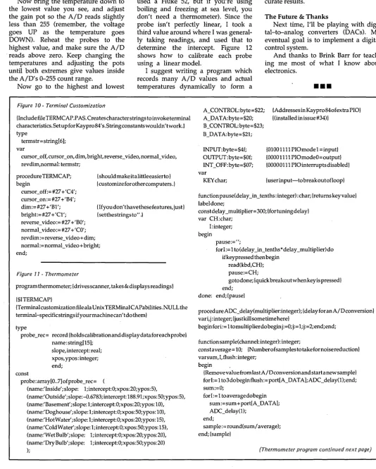
The Turbo Pascal program I've in-cluded (see Figures 10 and 11) has a record constant containing all the values for each probe, including name, location of screen output, slope, and in-tercept (assuming a simple linear model). I have one of the probes calibrated, and the rest have a slope of 1 and an intercept of 0 (which will just return the AID converter value). Start with all the values of slope= 1 and inter-cept=O.
adjust the offset pot so the A/D reads slightly above zero.
Now bring the temperature down to the lowest value you see, and adjust the gain pot so the A/D reads slightly less than 255 (remember, the voltage goes UP as the temperature goes DOWN). Reheat the probes to the highest value, and make sure the A/D -reads above zero. Keep changing the temperatures and adjusting the pots until both extremes give values inside the A/D's 0-255 count range.
temperatures and write down the count as well as the actual temperature (I
used a Fluke 52, but if you're using boiling and freezing at sea level, you don't need a thermometer). Since the probe isn't perfectly linear, I took a third value around where I was general-ly taking readings, and used that to determine the intercept. Figure 12 shows how to calibrate each probe using a linear model.
curve for each probe. Linear interpola-tion can then be used for much more ac-curate results.
The Future & Thanks
Next time, I'll be playing with digi- .' tal-to-analog converters (DACs). My eventual goal is to implement a digital control system.
And thanks to Brink Barr for teach-ing me most of what I know about electronics.
Now go to the highest and lowest
I suggest writing a program which records many A/D values and actual
temperatures dynamically to form a
•••
Figure 10- Terminal Customization
{IncludefileTERMCAP.PAs.Createscharacterstringstoinvoketerminal characteristics. Setup for Kaypro 84's. stringconstantswouldn' twork.} type
termstr=string[6]; var
cursor_off, cursor_on, dim, bright, reverse_video, normal_video, revdim,normal: termstr;
procedure TERM CAP; begin
cursocoff:=#27 +'C4'; cursor_on:=#27 +'B4'; dim:=#27+'Bl'; bright:=#27+'Cl'; reverse_video:= #27 + 'BO'; normal_video:= #27 + 'CO';
{should make ita little easier to } {customize for other computers .}
{If you don't have these features, just} {setthestrings to" .1
rev dim := reverse_video + dim; normal := normal_video + bright; end;
Figure 11 - Thermometer
program thermometer; {drives scanner, takes & displays readings}
{$ITERMCAPI
{Terminal customiza tion file ala Unix TERMinal CAPabilities. NULL the terminal-specificstringsifyourmachinecan'tdotheml
type
probe_rec= record {holdscalibrationanddisplaydataforeachprobe} name: string[l5];
slope, intercept: real; xpos, ypos: integer; end;
const
probe: array[0 .. 7] ofprobe_rec=
(name:'Inside';slope: 1;intercept:0;xpos:20;ypos:5),
(name:'Outside';slope:-O.6783;intercept:188.9l;xpos:50;ypos:5), (name:'Basement'; slope: 1; intercept: 0; x pos: 20; ypos: 10), (name:'Doghouse'; slope: 1; intercept: 0; xpos: 50;ypos: 10), (name:'Hot Water'; slope: 1; intercept: 0; xpos: 20;ypos: 15), (name:'Cold Water'; slope: 1; intercept: 0; xpos: 50;ypos: 15), (name:'Wet Bulb' ;slope: 1; intercept: O;xpos: 20;ypos: 20), (name:' Dry Bulb'; slope: 1;intercept:0;xpos:50;ypos:20)
);
A_CONTROL: byte =$22; A_DATA:byte=$20; B_CONTROL: byte= $23; B_DATA:byte=$2l;
INPUT: byte= $4f; OUTPUT:byte=$Of; INT_OFF:byte=$07; var
KEY char;
{AddressesinKaypr0840fextraPIO} {(installed in issue #34)}
{OlOOllll PIOmodel =inputl {DOOOllll PIOmodeO=output} {DOOOOlll PIOinterruptsdisabledl
{userinput-tobreakoutofloopl
functionpause(delay_in_tenths:integer):char;{returnskeyvalue} label done;
constdelay _multiplier=300; {fortuningdelay} var CH:char;
I: integer; begin
pause:=";
for 1:= 1 to (delay _in_tenths *delay _multiplier) do ifkeypressed then begin
read(kbd,CH); pause:=CH;
gotodone;{quickbreakoutwhenkeyispressed} end;
done: end; {pausel
procedureADC_delay(multiplier:integer);{delayforanA/Dconversion} vari, j: integer; {just kill some time here}
beginfori:= 1 tomultiplierdo begin j:=O;j:= 1;j:=2;end;end;
function sample(channel: integer): integer;
constaverage = 10; {Numberofsamples to take fornoise reduction} varsum,I, flush: integer;
begin
{RemovevaluefromlastA/Dconversionandstartanewsamplel forI:=l t03dobeginflush:=port[A_DATA];ADC_delay(l);end; sum:=O;
forI:=l toaveragedobegin sum:=sum+port[A_DATA]; ADC_delay(l);
end;
sample:= round(sum/ average); end; {samplel
(Thermometer program continued next page)
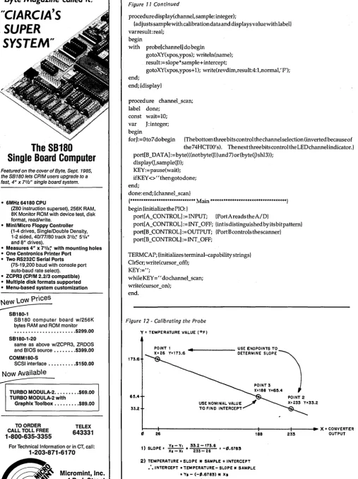
[image:14.617.35.570.92.759.2]Byte Magazine called it.
"C/ARC/A'S
SUPER
SYSTEM"
The SB180
Single Board Computer
Featured on the cover of Byte, Sept. 1985, the SB 180 lets CP/M users upgrade to a
fast, 4" x 7
'/2" single board system.
• 6MHz 64180 CPU
(Z80 instruction superset), 256K RAM, 8K Monitor ROM with device test, disk format, read/write.
• MinI/Micro Floppy Controller (1-4 drives, Single/Double Density, 1-2 sided, 40/77/80 track 3'12;' 5114" and 6" drives).
• Measures 4" x 71f2~ with mounting holes • One Centronics Printer Port
• Two RS232C Serial Ports (75-19,200 baud with console port auto-baud rate select).
• ZCPR3 (CP/M 2.2/3 compatible) • Multiple disk formats supported • Menu-based system customlzatlon
New
LoW
Prices;:.::;;---SB180-1
SB180 computer board w/256K bytes RAM and ROM monitor ••••••••.•••••••••.... $299.00 SB180-1-20
same as above w/ZCPR3, ZRDOS and BIOS source •••••••. $399.00 COMM180-S
SCSI interface ••••••.••• $150.00
Now Available
~---~
TURBO MODULA-2 ••••••••• $69.00 TURBO MODULA-2 with
Graphlx Toolbox •...••••• $89.00
TO ORDER CALL TOLL FREE
1-800-635-3355
TELEX
643331
For Technical Information or in CT, call:
1-203-871-6170
~
Micromini, Inc. [image:15.615.48.208.29.270.2] [image:15.615.53.561.43.721.2]~ 4 Park Street Vernon, CT 06066
Figure 11 Continued
proced ure display(channel, sample: integer);
{adjusts sample with calibration data and displays value with lab ell varresult:real;
begin
with probe [channel] do begin
gotoXY(xpos,ypos); writeln(name); result:=slope*sample+intercept;
gotoXY(xpos, ypos+ 1); write(revdim,result:4: 1 ,normal,' F'); end;
end; {display}
procedure channel_scan; label done;
const wait=10; var J:integer; begin
for J :=0 to 7 do begin {The bottom three bits control the channel selection (inverted because of the 74HCTOO's). The next three bits control the LEDchannelindicator.} port[B _DATA]:= byte( «not byte(J» and 7) or (byte(j) shI3»;
display(J,sample(J»; KEY:=pause(wait);
if KEY <>" thengotodone; end;
done: end; {channel_scan}
{****************************** Main ***********************************} begin {initializethePIO:}
port[A_CONTROL]:= INPUT; {PortA reads theA/D}
port[A_ CONTROL] := INT _OFF; {intis distinguished by its bit pattern} port[B _CONTROL] :=OUTPUT; {Port Bcontrols the scanner} port[B_CONTROL]:=INT_OFF;
TERM CAP; {initializes terminal-capability strings} ClrScr; write(cursor_off);
KEY:=";
while KEY =" do channel_scan; write(cursor_on);
end.
Figure 12 - Calibrating the Probe
Y' TEMPERATURE VALUE (OF)
173.6
.... 1--_ _ _ _ _ USE ENDPOINTS TO
DETERMINE SLOPE ~
POINT 3 X-I88 Ya6SA
615.4 POINT 2
33.2
r--~---~~---+----~~X=CONVERTER 26
1) SLOPE' !.!..=.!!. .. 33.2 -173.6 • -1/5 6783
XI-X, 233-26 •
2) TEMPERATURE. SLOPE
*
SAMPLE + INTERCEPT .'. INTERCEPT. TEMPERATURE - SLOPE*
SAMPL.E• 'Va - (-'.6783)
*
Xs.. 6S.4 + '.6783
*
188·192.91
TEXT LINE 6 COL: 12 FILE: VEDPLUS.TXT INSERT
I'
VEDIT PLUS is an advanced editor that makes your program development and word processing as efficient and easy as possible. VEDIT PLUS is simple eno!!9h to learn and use for the novice.l]et has the speed. flexibility ana power to satisfy the most demanding computer professional. VEDIT PLUS is particularly suited for writing all types of programs and lengthy documents such as reports or manuscripts.
This shows how VEDIT PLUS can perform windowing. One window is used for word processing. a second for program development. and the third for commands.
WINDOW
$---1---1
CHOICE IN
PROGRAMMABLE
EDITORS
VPLUSPC .COM INSTALL .EXE LlHARD LIGHT .COM ENVI .COM LONG VEDIT .INI RAM2 .DIC KEYS LIGHT .HLP RAM3 .DIC PRINT
VEDIT PLUS has been the #1 choice of professionals since 1980. Our latest release is even better - you can open windows to simultaneously edit several files, ac-cess many editing functions with pop-up menus, use keystroke macros to speed editing, and run other pro-grams or DOS commands from within VEDIT PLUS.
Whether your needs are program development, tech-nical writing or word processing, VEDIT PLUS is your answer. With over 40,000 users you can depend on VEDIT PLUS to perform consistently and reliably. It is simple enough to learn for the novice, yet has the speed, flexibility and power to satisfy the most de-manding professional.
Compare. No other editor is as powerful - unlimited keystroke macros, instant 'off-the-cuff' command mac-ros utilizing a complete programming language, sin-gle command file comparison, special word process-ing and programmprocess-ing features. No other editor is as easy to use - on-line help, pop-up menus, 75 page tutorial, 380 page manual, and VEDIT PLUS is
com-pletely customizable.
Fully supports color windows on IBM CGA & EGA, and even windowson most CRTterminals (including CRT's connected to an IBM PC). Available for IBM PC, TI Professional, Tandy 2000, DEC Rainbow, Wang PC, MS-DOS, CP/M-86 and CP/M-80. Order direct or from your dealer. $185
"To sum things up, VEDIT PLUS is a small, fast, sophisticated editor with a wealth of features and a good macro language. It offers many rewards forthe dedicated programmer."
Computer Language, Chris Wolf, Scott Lewis, Mark Gayman 6/86
"VEDIT PLUS is a wholly remarkabte program: bl indingly fast, extremely powerful, and highly flex-ible."
Profiles Magazine, Robert Lavenda 4/86
VEDIT and CompuView are registered trademarks of CompuView Products. Inc. MS-DOS is a registered trademark of Microsoft. CP/M is a registered trademark of Digital Research. WordStar is a registered trademark of MicroPro.
VEDIT PLUS FEATURES
• Simultaneously edit up to 37 files of unlimited size. • Split the screen into variable sized windows. • 'Virtual' disk buffering simplifies editing of large files. • Memory management supports up to 640K.
• Execute DOS commands or other programs. • MS-DOS pathname and CP/M user number support. • Horizontal scrolling - edit long lines.
• Flexible 'cut and paste' with 36 text registers.
• Customization - determine your own keyboard layout, create your own editing functions, support any screen size, any CRT. • Optimized for IBM PC/XT/AT. Also 132 column & up to 70 lines. EASY TO USE
• Interactive on-line help is user changeable and expandable. • On-line integer calculator (also algebraic expressions). • Single key search and global or selective replace. • Pop-up menus for easy access to many editing functions. • Keystroke macros speed editing, 'hot keys' for menu functions.
FOR PROGRAMMERS
• Automatic IndentiUndent for 'C', PUI or PASCAL. • Match/check nested parentheses, i.e. '{' and'}' for 'c'. • Automatic conversion to upper case for assembly language
labels, opcodes, operands with comments unchanged. • Optional 8080 to 8086 source code translator.
FOR WRITERS
• Word Wrap and paragraph formatting at adjustable margins. • Right margin justification.
• Support foreign, graphic and special characters. • Convert WordStar and mainframe files.
• Print any portion of file; separate printer margins.
MACRO PROGRAMMING LANGUAGE
• 'If-then-else', looping, testing, branching, user prompts key-board input, 17 bit algebraic expressions, variables.
• CRT emulation within windows, Forms entry.
• Simplifies complex text processing, formatting, conversions and translations.
• Complete TECO capability.
• Free macros: • Full screen file compare/merge. Sort mailing lists. Print Formatter. Main menu
CornpuView
1955 Pauline Blvd., Ann Arbor, MI 48103 (313) 996-1299, TELEX 701821
Swimming In The Relational Lake:
By Sandy Brabandt
6424 Sunnyfield Way Sacramento, CA 95823
An Introduction To Database Programming, Part 1
I thought I knew a lot about data bases and a lot about dogs. Now, I have to confess, I've been d'based. (And who let Dr. Dobbs in here?) Don't miss this first episode starring that famous heroine, Dee Base. (I'm sorry, it only gets worse.)
I
analyze the data collected in the 1870 t took 7 1/2 years to tabulate and U.S. census. Due to significant population growth, it looked like the 1890 census would take even longer, and that the information would be ob-solete by the time it was compiled.Enter Herman Hollerith, who had in-vented a machine that would read cen-sus data from holes punched in cards, tabulate it, and then analyze it. Using this machine, the census bureau was able to release population totals only a month after the data collection was complete, and a more thorough analysis was finished in 2 1/2 years -one-fourth of the original time es-timate.
This census tabulating machine was an important predecessor of the modern computer, and the punched cards were one of the first machine-readable statistical data files.
Data files still lie at the core of most computing - from a customer list kept by a newspaper carrier (on a Com-modore 64) to the massive taxpayer records kept by the IRS.
But data files have always been con-sidered a sort of ugly cousin to the more glamorous components of com-puter systems, the hardware and the programs. These get a great deal of at-tention, but data files, poor data files" are often created by haphazardly tack-ing data fields together as they're needed.
Files designed this way quickly be-come. unwieldy and difficult. This means that programs become more
complex in order to deal with the data. Updating a major system, once dif-ficult, becomes impossible.
A Little Theory Goes A Ways
The database concept came about as an answer to these problems. The con-ceivers (or theorists) proposed the fol-lowing simple guidelines for data files:
1) All the data used by an organiza-tion should be kept in one common base, and all systems should draw their data from this base.
2) The internal architecture of the data files should be kept independent from the applications. Each program should see only the data fields that it needs, and should navigate easily through the file structure. Changes to the files should have minimum impact on current applications.
3) The database should be easy to change and expand. You should be able to add and revise systems that use the currently existing files without having to tear apart the current file structures and start over.
4) There should be a structured design process for data files as rigorous as those for hardware and software. Data files should, in fact, be designed before the programs are written. In other words, system design should be data-driven rather than program-driven.
The theorists suggested several designs for file structures that would be easy to use and understand, and at the same time powerful and flexible enough to serve the needs of highly diverse systems. Among these was the Relational model for database structure introduced by E. F. Codd in 1970. The Codd Model
In this model, data is kept in tables, which are related to each other via com-mon data elements. This model gained support throughout the academic
com-munity for its flexibility and ease of use.
However, for a long time that sup-port didn't extend into the business world, mainly because neither hard ware nor software were powerful enough.
If you were working in data process-ing in 1970, you probably remember the card files, very similar to those in-vented by Herman Hollerith. The clean and elegant relational theory wasn't all that clean and elegant when the data came from trays of cards.
Even magnetic tape, which was a much faster, more accurate, and less bulky mode of data storage, was inade-quate for relational databases, since the relational model required direct access storage devices. It wasn't until shops could afford large disk drives that they began using relational databases.
Even after the hardware was in place, it was years before software began supporting relational databases. Big Blue's DB2, a relational database product for mainframes, is just begin-ning to catch on. And, because it's an enormous resource hog, it's mainly used as a peripheral product to support end-user queries rather than as a day-to-day workhorse.
In general, mainframe-oriented data processing shops are just sticking their big toes into the relational database lake. Microcomputer users, however, have been happily swimming in the relational lake for a number of years.
Enter dBASE II
It all began with the introduction of a software product called dBASE II. Despite the fact that it was expensive and as buggy as an anthill, this product was so far ahead of anything else avail-able at the time that it became an in-stant bestseller.
RAM, a variety of dBASE II upgrades (such as dBASE III) and spinoffs (such as R: base 5000 and Paradox) hit the market.
Micro users had everything they needed to build sophisticated relational database systems. Unfortunately, most of them still lacked something. They didn't know how to use them well. Dr. Dobbs & Relational Confusion
For example, let's look at a typical case of Relational Confusion: a hypothetical dBASE III user, a veterinarian named Dr. Dobbs (no rela-tion).
Dobbs has decided to write a system to keep track of his practice. In be-tween spaying and neutering his clien-tele, administering rabies vaccinations, and removing foxtails from noses, he's managed to read his dBASE III manual and do a bit of tinkering. He's eager to start programming.
A Bird In The Hand
So he sits down at his Eagle com-puter and cranks up dBASE to CREATE a data file. Adhering to tradi-tional file design technique, he starts throwing data elements into it.
He starts with information about the pet owners. For each owner he wants to store a name, address, phone num-ber, and current account balance. Then he needs information about the owner's pet: the type of animal, its name, breed, weight, and color.
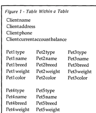
[image:18.623.47.213.541.736.2] [image:18.623.411.574.614.733.2]Dobbs is a pretty sharp guy, and he immediately sees a shortcoming in this record layout: he's only defined fields for one pet per client, and many clients have more than one. He decides to
Figure 7 -Table Within a Table
Client name Client address Client phone
Clien t current accoun t balance
Petltype Pet2type Pet3type
Petlname Pet2name Pet3name
Petl breed Pet2breed Pet3breed Petl weight Pet2weight Pet3weight
Petlcolor Pet2color Pet3color
Pet4type Pet5type
Pet4name Pet5name
Pet4breed Pet5breed Pet4weight Pet5weight Pet4color Pet5color
make room in the record for more than one pet - in other words, to put a pet table within each client record.
After some consideration, he con-cludes that space for five pets per client should be adequate, and ends up with a record definition that looks like Figure 1.
Of course, most of his clients don't have five pets, which means he's wasted quite a bit of space. But he decides that, with his twenty-meg hard disk, he can live with some wasted space.
Things are going along fairly well until one day he goes to input the data for one client, Bowwow Kennels. Edith Bowwow owns 12 dogs and brings them all to Dr. Dobbs. Dobbs con-templates splitting the Bowwow, dogs across three records, but quickly sees just how complicated the programming could get. He revises his scheme. He bases his files on the pets rather than their owners, and comes up with a one-record-per-pet design. It looks vaguely like Figure 2.
Now it takes twelve records to hold the information about Mrs. Bowwow and her dogs, and the information for Mrs. Bowwow is repeated all twelve times.
Dobbs is a little concerned about the extra space it will take to store all of that duplicate data, but he figures his hard disk can handle it. He also figures that his office staff can enter the Mrs. Bowwow data 12 times.
Soon after, Mrs. Bowwow calls to say she's moved, and gives them her new address. The office staff (after a minor revolt) has to change her address in twelve places. However, being human (can't Dobbs get anything right?), they miss making the change for the record holding information about her dog Phydeaux.
Later that month, she brings Phydeaux in for vaccinations, and as usual, they put the charges on her ac-count. They then mail the bill to her old address.
The bill gets hopelessly mired in the Postal Service's forwarding routines, and Mrs. Bowwow never receives it. However, she does receive an eventual phone call from the office asking why she hasn't paid her bill. Since she has never even received the bill, she's out-raged, and promptly takes all of her vet business elsewhere.
Dismayed Dobbs
Dobbs is dismayed. He bought The Computer to help his business, not destroy it. So, he decides to give in and hires a consultant to help design his system.
The consultant, Dolores Base (known to friends as Dee), examines Dobbs' two desi'gns and announces that Dobbs has committed two database design crimes.
The first design contains a Repeat-ing Group of data elements - the table-within-a-table. This kind of sub-table is hard to manage, wastes space if it's underutilized (if a client has fewer than five pets), and proves un-work-able if it's inadequate in size (if a client has more than five pets).
The second design contains Redun-dant Data (Mrs. Bowwow's name and address repeated twelve times). Redun-dant data wastes space and effort by storing the same information over and over again, but more importantly, it causes an erosion of data integrity when it's not properly maintained (as when Mrs. Bowwow's address wasn't changed in Phydeaux's record).
Dobbs acknowledges the truth in everything Ms. Base is saying, but he wants to know one thing: how SHOULD his files be designed?
For the moment, let's leave Dobbs with his database and regress a bit.
To get to first base with Ms. Base, you first need to understand some basics about relational databases. Since dBASE III is the most commonly used relational database management system (DBMS), I'll use it for my examples. Relational Database
Relational databases are composed of sets of tables. dBASE III keeps each table in a separate physical file, al-though other programs may not.
A row in a table corresponds to a
(continued next page)
Figure 2 -Data Base With Redundant Data
eettype Pet name Pet breed Pet weight Pet color
Pet owner (client name) Client address Clientphone
Client current account balance
(continued from page 15)
record' in a traditional file, and a column corresponds to a field. Physical-ly, a relational table resembles a tradi-tional data file, but the ways they're used are very different.
Traditional file handling is record-oriented. The programs read the file a record at a time; each record is presented to the program as a string of data, and' the program is responsible for mapping the fields in that string. This means that if the organization of data in the string is changed in any way, the mapping also has to be changed in every program that uses that file.
Relational table handling is more column-oriented. A program using a relational table will set a file pointer to the row it's interested in, and will then examine the data in that row by using the names of the column headers.
The column definitions are stored and managed by the DBMS. In dBASE III, for instance, the column header names, and the length and type of data
eleme~t in each column, are stored at the beginning of the data file. This means that you can add and rearrange columns extensively without affecting your programs. The table tells the program where to find the data fields it needs. Thus, the order of columns in a table isn't important. Two tables are functionally the same if they have the same data, even though that data is in a different order.
Because the column mapping for a relational database is done by the DBMS, all relational databases are inex-tricably linked to the DBMS that created them. The DBMS provides the means to create a table definition and to access, update, add, and delete data in that table. This can, of course, be somewhat limiting.
Sharing Files
Most producers of relational DBMSs realize this and provide some way to make their tables readable by other lan-guages or systems. For instance, IBM has provided a "pre-compiler" so that you can imbed statements from SQL (the data access language for IBM's DB2 databases) in programs written in several common mainframe languages.
dBASE III includes commands that will translate its table structures into other commonly-used data structures.
In addition, due to dBASE Ill's popularity, many other software products can read dBASE III tables.
In exchange for this limitation, a rela-tional DBMS will give you considerable power. As described above, it frees you from having to map data within your programs. It also provides the ability to do several operations that are critical to managing'relational databases. Three of these operations - Select, Project, and " Join - are so critical that a DBMS
can-not really. be considered "relational" without them.
The Select operation allows you to select certain rows within a table by specifying that certain data values must