,
, •~ylogiCS)
Model7S2
User's Manual
( . , 4 ~ ... l ...
...
YOUR PARTNER FOR PERFORMANCE.
166·752·001
Revision
A
The information in this manual is subject to change without
notice, and should not be construed as a commitment by Xylogics.
~XylogiCS)
Model7S2
User's Manual
! ' , 4
~..
.-...
I.
"YOURPARTNERFORPERFORMANC~
166-752-001
Revision A
XYLOOIQ) 752 Disk Controller User I s Manual
752 REVISIOO LE.VEL HIS'roRY
REVISION DESOUPl'ION
---,---I
A (6/15/87) I Initial release.XYLOGICS 752 Disk Controller User's Manual
PAGE
LIST OF ILLUSTRATIONS ••••••••••••••••••••••••••••••••••••••••••••••• xi SECl'ION 1: SPECIFICATIONS
1.0 ~ •••••••••••••••••••••••••••••••••••••••••••••••••••••••• 1
1.1 USnl3
mrs
~...•...
1 1.1.1 Abbreviations •••••••••••••••••••••••••••••••••••••••••• 1 1.2 DESI~ REl:..IABILITY ••••••••••••••••••••••••••••••••••••••••••••• 21.3 PHYSlCAr. ••••••••••••••••••••••••••••••••••••••••••••••••••••••• 3
1.4 m\Tm~ •••••••••••••••••••••••••••••••••••••••••••••••••• 3
1.5 E:I..ECI'R.I CAr. ••••••••••••••••••••••••••••••••••••••••••••••••••••• 3
1.6 SY~l RELAT.ED SPECIFICATIONS •••••••••••••••••••••••••••••••••• 3
1.7 DISK DRIVE RELATED SPECIFICATIONS
...
51.8 VT~bus ~TED SPECIFICATIONS •••••••••••••••••••••••••••••••••• 6
1.9 SOFTWARE RELATED SPECIFICATIONS •••••••••••••••••••••••••••••••• 7
1.9.1 Software Interface ••••••••••••••••••••••••••••••••••••• 7
1.10 PR.~ E'EA'ltJRES •••••••••••••••••••••••••••••••••••••••••• 8
SEcrION 2: INsrALLThG AND TFSTm; mE 752
2.0 2.1
2.2
~ •••••••••••••••••••••••••••••••••••••••••••••••••••••••• 9
tJm>Aa<nl3 AND INsmcrION ••••••••••••••••••••••••••••••••••••••• 9 2.1.1
2.1.2 2.1.3 2.1.4
Inspect the Shipping carton ••••••••••••••••••••••••••••
Contents
...
Handling Precautions ••••••••••••••••••••••••••••••••••• Inspect the 752 ••••••••••••••••••••••••••••••••••••••••
9 9 9 9
CONFIGURING THE 752 ••••••••••••••••••••••••••••••••••••••••••• 10
2.2.1 2.2.2 2.2.3
Base Address Selection •••••••••••••••••••••••••••••••• Bus Request and Bus Grant Lines ••••••••••••••••••••••• Parallel Arbitration ••••••••••••••••••••••••••••••••••
11
XYLOGICS 752 Disk Controller Userls Manual
TABLE OF CXNmNTS
PAGE
2.3 PR.(}4.,g Al\JD P.AI.S •••••••••••••••••••••••••••••••••••••••••••••••• 13
2.4 SELF TEST DISABLE
...
132.5 •••••••••••••••••••••••••••••••••••••••••••••••• 13
2.6 LIGHT EMITTING DIODES ••••••••••••••••••••••••••••••••••••••••• 13
2.7 BOARD LABELS / REVISION CONTROL ••••••••••••••••••••••••••••••• 13
2.8
2.9
2.10
PREPARnX; '!HE <n1IUTER SYSTEM FOR INSTALLATION •••••••••••••••• 14
2.8.1 2.8.2 2.8.3
Backplane Jumpers ••••••••••••••••••••••••••••••••••••• 14
card cage Slot •••••••••••••••••••••••••••••••••••••••• 14
Power Considerations •••••••••••••••••••••••••••••••••• 14
PREPARnG '!HE DISK DRIVE FOR INsrALLATION
...
152.9.1 2.9.2 2.9.3 2.9.4 2.9.5
Drive Unit Select ••••••••••••••••••••••••••••••••••••• 15 Number of Sectors Per Track ••••••••••••••••••••••••••• 15 Sector and Index Pulses ••••••••••••••••••••••••••••••• 15
Tags 4 and 5 •••••••••••••••••••••••••••••••••••••••••• 15
Extended CYlinder Addressing •••••••••••••••••••••••••• 16
mITIAI. ~'lS ••••••••••••••••••••••••••••••••••••••••••••••••• 16
2.10.1 2.10.2
Power-up and Self Test ••••••••••••••••••••••••.•••••••• 16
Drive Reaqy ••••••••••••••••••••••••••••••••••••••••••• 16
2.11 DI~ICS ••••••••••••••••••••••••••••••••••••••••••••••••••• 16
SEC'rION 3: '!HE 752 REGISTERS
3.0 GENERAL ••••••••••••••••••••••••••••••••••••••••••••••••••••••• 17
3.1 lOPS ADDRESS REGISTERS •••••••••••••••••••••••••••••••••••••••• 17
3.2 lOPS ADDRESS MDDIFIER ••••••••••••••••••••••••••••••••••••••••• 17
ii
XYLOGICS 752 Disk COntroller User's Manual
TABLE OF CXNl'EN.IS
PAGE
3 • 3 <X>NTROL AND STA'lUS REX:;ISTER ••••••••••••••••••••••••••••••••••• 18
3.3.1 3.3.2
Control Register (Write) •••••••••••••••••••••••••••••• 18 Status Register (Read) •••••••••••••••••••••••••••••••• 20
3.4 FATAIa ERROR REX:;ISTER •••••••••••••••••••••••••••••••••••••••••• 22
SEcrlON 4: IOPB DESOUPl'ION
4.0 ~RAI.. ••••••••••••••••••••••••••••••••••••••••••••••••••••••• 23
4.1
srN\JmRD roPB •••••••••••••••••••••••••••••••••••••••••••••••••
234.1.1 4.1.2 4.1.3 4.1.4 4.1.5 4.1.6 4.1. 7 4.1.8 4.1.9 4.1.10 4.1.11 4.1.12 4.1.13 4.1.14 4.1.15 4.1.16 4.1.17 4.1.18 4.1.19
lOPS Byte 0 (Command) ••••••••••••••••••••••••••••••••• 24
lOPS Byte 1 (Status Byte 1) ••••••••••••••••••••••••••• 25
lOPS Byte 2 (Status Byte 2) ••••••••••••••••••••••••••• 26 lOPS Byte 3 (Status Byte 3) • • • • • • • • • • • • • • • • • • • • • • • • • •• 26
lOPS Byte 4 (Subfunction) ••••••••••••••••••••••••••••• 26
lOPS Byte 5 (Unit) •••••••••••••••••••••••••••••••••••• 28
lOPS Byte 6 (Interrupt Level) ••••••••••••••••••••••••• 29
lOPS Byte 7 (Interrupt Vector) •••••••••••••••••••••••• 29
lOPS Bytes 8 and 9 (COunt) •••••••••••••••••••••••••••• 29
lOPS Bytes A and B (CYlinder) ••••••••••••••••••••••••• 29
IOPS Byte C (Head) •••••••••••••••••••••••••••••••••••• 30
lOPS Byte D (Sector) •••••••••••••••••••••••••••••••••• 30 lOPS Byte E (Data or Link Address Modifier) ••••••••••• 30
lOPS Byte F (Next lOPS Address Modifier) •••••••••••••• 30
lOPS Bytes 10 Through 13 (OMA Data Address) ••••••••••• 31
lOPS Bytes 14 Through 17 (Next lOPS Address) •••••••••• 31 lOEB Bytes 18 and 19 (lOEB Checksum) •••••••••••••••••• 31 lOPS Bytes lA and lB (ECC Pattern Word) ••••••••••••••• 31 lOPS Bytes lC and lD (ECC Offset Word) •••••••••••••••• 31
4.2 OONT.ROLLER PARAMETERS lOPS •••••••••••••••••••••••••••••••••••• 32
4.2.1 4.2.2 4.2.3 4.2.4 4.2.5 4.2.6 4.2.7 4.2.8
lOPS Byte 8 lOPS Byte 9 lOPS Byte A lOPS Byte B
(COntroller Parameters A) (Controller Parameters B) (Controller Parameters C) (Controller Parameters D)
·
·
... .
... .
·
... .
·
... .
lOPS Byte C (EPROM Release Level) •••••••••••••••••••••lOPS Byte E (COntroller TYPe) •••••••••••••••••••••••••
lOPS Bytes 10 and 11 (EPRO-i Part Number) •••••••••••••• lOPS Byte 12 (EPROM Revision Level) •••••••••••••••••••
XYLOOIQ; 752 Disk COntroller User I s Manual
4.3
4.4
TABLE OF <DJ'l'mJS
PAGE
DRIVE PARAMETERS lOPS •••••••••••••••••••••••••••••••••••••••••
4.3.1 4.3.2 4.3.3 4.3.4 4.3.5 4.3.6 4.3.7
lOPS Byte 6
lOPS Byte 8 (Drive Parameters) •••••••••••••••••••••••• (Max Sector/Last Head) •••••••••••••••••••• lOPS Byte 9 (Head Offset) ••••••••••••••••••••••••••••• DOPS Bytes A and B (Max CYlinder) ••••••••••••••••••••• •••••••••••••••••••••••••••••••• lOPS Byte C (Max Head)
lOPS Byte D (Max Sector) •••••••••••••••••••••••••••••• lOPS Byte E (Sectors Per Track) •••••••••••••••••••••••
37 38 39 39 39 39 39 39
FORfoJA.T PARAMETERS lOPS •••••••••••••••••••••••••••••••••••••••• 40
4.4.1 4.4.2 4.4.3 4.4.4 4.4.5 4.4.6 4.4.7 4.4.8 •••••••••••••••••••••••••••••• ( Interleave)
(Field 1) lOPS Byte 9 (Field 2) lOPS Byte A (Field 3)
lOPS Byte B (Field 4) DOPS Byte 6
lOPS Byte 8 •••••••••••••••••••••••••••••••••
•••••••••••••••••••••••••••••••••
•••••••••••••••••••••••••••••••••
•••••••••••••••••••••••••••••••••
lOPS Bytes C and D (Bytes Per Sector High/Low) •••••••• lOPS Byte 10 (Field 6)
DOPS Byte 11 (Field 7) •••••••••••••••••••••••••••••••• •••••••••••••••••••••••••••••••• 40 41 41 42 42 42 42 42
SEcrION 5:
5.0 5.1 5.2 5.3 5.4 5.5 5.6
••••••••••••••••••••••••••••••••••••••••••••••••••••••• 43
5.0.1 5.0.2
Setting Up The Command •••••••••••••••••••••••••••••••• 43
~leting The Command •••••••••••••••••••••••••••••••• 43
00 OPERATION •••••••••••••••••••••••••••••••••••••••••••••••••• 44 WRITE DATA •••••••••••••••••••••••••••••••••••••••••••••••••••• 45
READ M.TA ••••••••••••••••••••••••••••••••••••••••••••••••••••• 46
REPORT CURRENT ADDRESS •••••••••••••••••••••••••••••••••••••••• 47 SEEK AND REPORt' <lJRRmI' ADDRESS ••••••••••••••••••••••••••••••• 48 START SEEK AND REPORT ClloiPLETION IMmDIATELY •••••••••••••••••• 49
5.7 DRIVE RESET ••••••••••••••••••••••••••••••••••••••••••••••••••• 50
5.8 WRITE aEmCLLER PARAMETERS ••••••••••••••••••••••••••••••••••• 51 5.9 WRITE DRIVE P.ARAf.mTERS •••••••••••••••••••••••••••••••••••••••• 52
iv
[image:10.613.66.529.80.727.2]X!LOGICS 752 Disk Controller User's Manual
TABLE OF cx:mHfiS
PAGE
5.10 WRITE FO~ PARAMETERS ••••••••••••••••••••••••••••••••••••••• 53
5.11 READ CONTROLLER P~~T.ERS •••••••••••••••••••••••••••••••••••• 54
5.12 READ DRIVE PARAMEi'ERS ••••••••••••••••••••••••••••••••••••••••• 55
5.13 READ E'ORfwlA.T PARAMEi'ERS •••••••••••••••••••••••••••••••••••••••• 56
5.14 READ DRIVE STATUS EXTENDED •••••••••••••••••••••••••••••••••••• 57
5.15 WRITE TRACK HEADERS ••••••••••••••••••••••••••••••••••••••••••• 58
5.16 WRITE ~T •••••••••••••••••••••••••••••••••••••••••••••••••• 59
5.17 WRITE HEADER, HEADER VERIFY, Dl\.TA, AND DATA ECC
...
605.18 WRITE DEFECl' MAP
...
615.19 WRITE DEFECl' MAP EXTENDED ••••••••••••••••••••••••••••••••••••• 62
5.20 READ TRACK HEADERS •••••••••••••••••••••••••••••••••••••••••••• 63
5 • 21 VERIFY Dl\.TA ••••••••••••••••••••••••••••••••••••••••••••••••••• 64
5.22 READ HEADER, HEADER VERIFY, Dl\.TA, AND Dl\.TA ECC •••••••••••••••• 65
5.23 READ DEFECl' MAP ••••••••••••••••••••••••••••••••••••••••••••••• 66
5.24 READ DEFECT MAP EXTENDED •••••••••••••••••••••••••••••••••••••• 67
5.25 DI~Ic:.g ••••••••••••••••••••••••••••••••••••••••••••••••••• 68
SECl'ION 6: ERROR PROCESSm;
6.0
6.1
6.2
~ ••••••••••••••••••••..••••••••••••••••••••••••••••••••• 69
'!lIE mtPI.ETIOO (DDE ••••••••••••••••••••••••••••••••••••••••••• 69
6.1.1 6.1.2
Completion Code Convention •••••••••••••••••••••••••••• Completion Code Descriptions ••••••••••••••••••••••••••
69
70
SOFT ERROR OOMPLETiOO aoDES ••••••••••••••••••••••••••••••••••• 76
[image:11.612.92.527.92.631.2]-v-XYLOGICS 752 Disk Controller User's Manual
TABLE OF CCNl'ENTS
PAGE
6.3 ERroR mRRECrION mDE ••••••••••••••••••••••••••••••••••••••••• 76
6.3.1 6.3.2 6.3.3
Error Correction Code
Error Correction Code
Error Correction Code
Mode 0 Model
Mode 2
•••••••••••••••••••••••• •••••••••••••••••••••••• •••••••••••••••••••••••• 76 77 77
6.4 FA~ ERroR mOE DESCRIPTIONS ••••••••••••••••••••••••••••••••• 77
SEcrION 7: A '1U'IORIAL IN PROORru.1MlN2 '!HE 752
7.0 7.1 7.2 7.3 7.4 7.5 7.6
~ ••••••••••••••••••••••••••••••••••••••••••••••••••••••• 79
00 Ol?ERA.TION •••••••••••••••••••••••••••••••••••••••••••••••••• 79
7.1.1 7.1.2 7.1.3 7.1.4 7.1.5 7.1.6
Allocating Memory For An lOPS ••••••••••••••••••••••••• 80
Point the 752 to the lOEB ••••••••••••••••••••••••••••• 80
Starting the Operation •••••••••••••••••••••••••••••••• 80
752 Operation ••••••••••••••••••••••••••••••••••••••••• 80
COmmand.C~etion •••••••••••••••••••••••••••••••••••• 81 Returned Values ••••••••••••••••••••••••••••••••••••••• 81
READ a:N1'RCLLER PARAMETERS •••••••••••••••••••••••••••••••••••• 81
7.2.1 7.2.2 7.2.3
Execute the lOEB •••••••••••••••••••••••••••••••••••••• 81
752 Operation ••••••••••••••••••••••••••••••••••••••••• 81
The Returned lOEB ••••••••••••••••••••••••••••••••••••• 82
WRITE CDNTRCLLER PARAMETERS
...
837.3.1 752 Operation ••••••••••••••••••••••••••••••••••••••••• 83
READ/WRITE FORMAT PARAMETERS •••••••••••••••••••••••••••••••••• 84
7.4.1 7.4.2 7.4.3 7.4.4
Execute the lOPS with Interrupts •••••••••••••••••••••• 84
752 Operation ••••••••••••••••••••••••••••••••••••••••• 85
COmmand ~etion •••••••••••••••••••••••••••••••••••• 85
Returned Values ••••••••••••••••••••••••••••••••••••••• 85
READ/WRITE DRIVE PARAMETERS ••••••••••••••••••••••••••••••••••• 85
7.5.1 752 Operation ••••••••••••••••••••••••••••••••••••••••• 85
FORMAT A TRACK •••••••••••••••••••••••••••••••••••••••••••••••• 86
7.6.1 752 Operation ••••••••••••••••••••••••••••••••••••••••• 87
vi
[image:12.612.66.503.199.676.2]xn.ooICS 752 Disk Controller User's Manual 7.7 7.8 7.9 7.10 7.11
TABLE OF <DnDl.IS
PAGE
READ 'lRACI{ HEADERS •••••••••••••••••••••••••••••••••••••••••••• 88
7.7.1 7.7.2
752 Operation ••••••••••••••••••••••••••••••••••••••••• 89
Veri~ing the Data •••••••••••••••••••••••••••••••••••• 90
liRITE DA.TA •••••••••••••••••••••••••••••••••••••••••••••••••••• 91
7.8.1 7.8.2
752 Operation ••••••••••••••••••••••••••••••••••••••••• 92
Command Completion •••••••••••••••••••••••••••••••••••• 92
READ DA.TA ••••••••••••••••••••••••••••••••••••••••••••••••••••• 92
7.9.1 7.9.2 7.9.3
752 Operation ••••••••••••••••••••••••••••••••••••••••• 92
Command COmpietion •••••••••••••••••••••••••••••••••••• 92
Veri~ Data ••••••••••••••••••••••••••••••••••••••••••• 93
MULTrPLE SECTOR TRANSFERS ••••••••••••••••••••••••••••••••••••• 94
~y ••••••••••••••••••••••••••••••••••••••••••••••••••••••• 94 SEcrION 8: smCIAL FUNCrIONS
8.0
8.1
8.2
8.3
~ ••••••••••••••••••••••••••••••••••••••••••••••••••••••• 95
READ DEFECT MAP ••••••••••••••••••••••••••••••••••••••••••••••• 95
8.1.1 8.1.2 8.1.3 8.1.4
The Defect Map ••••••••••••••••••••••••••••••••••••••••
Read the Defect Map •••••••••••••••••••••••••••••••••••
Veri~ the Data ••••••••••••••••••••••••••••••••••••••• Determining the Location of a Defect ••••••••••••••••••
95 96 96 97
~ •••••••••••••••••••••••••••••••••••••••••••••••••••• 97
8.2.1 8.2.2 8.2.3
Allocating Spare Sectors •••••••••••••••••••••••••••••• 97
speci~ Sector Gap Size ••••••••••••••••••••••••••••••• 97 For:mt Interleave •••••••••••••••••••••••••• '... 100
MEDIA DEFECr HANILn13 •••••••••••••••••••••••••••••••••••••••• 101 8.3.1
8.3.2 8.3.3 8.3.4
Slipping a Sectoc •••••••••••••••••••••••••••••••••••• 101 GYlinder Sparing ••••••••••••••••••••••••••••••••••••• 103
Track Remapping •••••••••••••••••••••••••••••••••••••• 104 Recommended Remapping Procedure •••••••••••••••••••••• 105
[image:13.613.93.537.96.769.2]mroICS 752 Disk Controller User's Manual
8.4
TABLE OF CXHLm'.IS
PAGE
ClIAINIK; AND MULTIPLE I/O REOJESTS ••••••••••••••••••••••••••• 105
8.4.1 8.4.2 8.4.3
Chaining ••••••••••••••••••••••••••••••••••••••••••••• 106
Multiple I/O ~sts •••••••••••••••••••••••••••••••• 106
752 Operation •••••••••••••••••••••••••••••••••••••••• 106
8.5 ERROR RECOVERy ••••••••••••••••••••••••••••••••••••••••••••••• 106
8.6
8.7
8.5.1 8.5.2 8.5.3
Automatic Operation Ret~ •••••••••••••••••••••••••••• 106
ECC Error Reoove~ ••••••••••••••••••••••••••••••••••• 107
Using the Error Reoove~ Options ••••••••••••••••••••• 107
MAINTENANCE K>DE ••••••••••••••••••••••••••••••••••••••••••••• 107 8.6.1
8.6.2 Register Use in Maintenance
Mode ••••••••••••••••••••• 107
Maintenance Mode Protocol •••••••••••••••••••••••••••• 108
MULTIPROCESSOR SUPPORl' ••••••••••••••••••••••••••••••••••••••• 109
8.7.1 8.7.2 8.7.3
Interrupts ••••••••••••••••••••••••••••••••••••••••••• 109
Register Busy Semaphore •••••••••••••••••••••••••••••• 110
Address Modifiers •••••••••••••••••••••••••••••••••••• 110
8.8 SO~ARE OONT.ROL ••••••••••••••••••••••••••••••••••••••••••••• 110
8.9
8.10
8.11
8.8.1 8.8.2 8.8.3
Modi~ing a Single Parameter ••••••••••••••••••••••••• 110
Modi~ing a Group of Parameters •••••••••••••••••••••• 110
Parameter Reference Point •••••••••••••••••••••••••••• III
~~~ ••••••••••••••••••••••••••••••••••••••••••••••• 111
8.9.1 8.9.2 8.9.3
Scatter/Gather Link List ••••••••••••••••••••••••••••• III
Setting Up a Scatter/Gather Transfer ••••••••••••••••• 112
752 Operation •••••••••••••••••••••••••••••••••••••••• 113
rMA 'lBR<7.rlLE / 'lBR<7.rlLE DEAD TIME •••••••••••••••••••••••••••• 114
lOPS CHECKSUM •••••••••••••••••••••••••••••••••••••••••••••••• 114
viii
[image:14.613.80.523.67.615.2]XYLOGICS 752 Disk Controller User's Manual
TABLE OF CXNrEN'lS
PAGE
8.12 FlXED/REmVABLE MEDIA
...
1148.12.1 Head Otfset •••••••••••••••••••••••••••••••••••••••••• 114
8.13 EMBEDDED SERVO DRIVES
...
115 8.14 WAr., OORI'ED DRIVES ••••••••••••••••••••••••••••••••••••••••••• 1158.14.1 Software Write Access Control •••••••••••••••••••••••• 116 8.15 READ/WRITE HEADER, HEADER VERIFY, DA.TA, AND DA.TA ECC ••••••••• 116 8.15.1 Sllnulating an ECC Error
...
1178.16 REI..EASE (l\J RE::QUES'I' ••••••••••••••••••••••••••••••••••••••••••• 118
SECl'ION 9: 'llIEORY OF OPERATION
9 .0 Gm'ERAI.. •••••••••••••••• ~ • • • • • • • • • • • • • • • • • • • • • • • • • • • • • • • • • • • •• 119
9.1 The Hardware ••••••••••••••••••••••••••••••••••••••••••••••••• 119 9.1.1
9.1.2 9.1.3 9.1.4 9.1.5 9.1.6 9.1. 7
9.1.8 9.1.9 9.1.10
VMEbus Interface ••••••••••••••••••••••••••••••••••••• 119
Register Read/Write and Interrupt •••••••••••••••••••• 119
The Microcontroller •••••••••••••••••••••••••••••••••• 120
D1rect Memory Access Controller •••••••••••••••••••••• 121
Disk Data Buffer ••••••••••••••••••••••••••••••••••••• 122 Disk Front End ••••••••••••••••••••••••••••••••••••••• 122 SMD-E Interface •••••••••••••••••••••••••••••••••••••• 122 Power-up ••••••••••••••••••••••••••••••••••••••••••••• 123 Power-down ••••••••••••••••••••••••••••••••••••••••••• 123 $ystem Reset ••••••••••••••••••••••••••••••••••••••••• 123
9.2 THE MICROODDE •••••••••••••••••••••••••••••••••••••••••••••••• 123
9.2.1 9.2.2 9.2.3 9.2.4 9.2.5
The Kernel ••••••••••••••••••••••••••••••••••••••••••• 123 Is AlO Set? •••••••••••••••••••••••••••••••••••••••••• 124
Is Start Queue Empty? •••••••••••••••••••••••••••••••• 125
Is Any IOPB Reaqy for Completion? •••••••••••••••••••• 125
Queuing IOPBs for Execution •••••••••••••••••••••••••• 125
[image:15.615.100.540.315.673.2]XYLOOICS 752 Disk Controller User' s Manual
9.3
TABLE OF cx:NrEmS
PERFORMIN.; A FUNcrION
...
9.3.1 9.3.2 9.3.3 9.3.4 9.3.5 9.3.6 9.3.7 9.3.8 9.3.9
IDP ••••••••••••••••••••••••••••••••••••••••••••••••••
Normal Reads and Writes ••••••••••••••••••••••••••••••
Seeks
...
Drive Reset ••••••••••••••••••••••••••••••••••••••••••Write and Read Parameters •••••••••••••••••••••••••••• Extended Read and Write Commands •••••••••••••••••••••
Diagnostics ••••••••••••••••••••••••••••••••••••••••••
Read Ahead Theory of Operation ••••••••••••••••••••••• Dyna-throttle Theory of Operation ••••••••••••••••••••
PAGE
125
125
126
126 126 127 127
127
128 128
9.4 COMPLETiNG A FUNCTION •••••••••••••••••••••••••••••••••••••••• 128
SEcrION 10: DRIVE INTERFACE
10.0 GENERAL •••••••••••••••••••••••••••••••••••••••••••••••••••••• 129
10.1 VMEbus INTERFACE SIGNALS ••••••••••••••••••••••••••••••••••••• 130
10.2 EXTENDED STORAGE l«)IXJLE DRIVE INTERFACE •••••••••••••••••••••• 132
[image:16.615.55.506.74.405.2]XYLOGICS752 Disk Controller User's Manual FIGURES 2-1. 2-2. 2-3. 2-4. 7-1. 7-2. 7-3. 7-4. 7-5. 7-6. 7-7. 7-8. 7-9. 7-10. 8-1. 8-2. 8-3. 8-4. 8-5. 8-6. 8-7. 8-8. 8-9. 8-10. 9-1. 2-1. 2-2. 3-1. 3-2. 4-1. 4-2. 4-3. 4-4. 4-5. 5-1. 5-2. 6-1. 6-2. 8-1. 8-2. 8-3. 8-4. 8-5. 8-6. PAGE
752 - Ocmponent Location •••••••••••••••••••••••
Base Address Jumper Block •••••••••••••••••••••• Jumpering Bus Request and Bus Grant Levels •••••
10 11 12 Sample Part Number ••••••••••••••••••••••••••••• 13
sam~e NOP lOEB •••••••••••••••••••••••••••••••• Sample Read Controller Parameters lOEB ••••••••• Sample Write Controller Parameters lOEB ••••••••
Sam~e Read Format Par ameters lOEB ••••••••••••• Sample Write Drive Parameters lOEB ••••••••••••• Sample Write Format lOEB ••••••••••••••••••••••• Sample Read Track Headers lOEB ••••••••••••••••• Sample Sector Headers •••••••••••••••••••••••••• Sample Write Data lOEB ••••••••••••••••••••••••• Sample Read Data lOEB •••••••••••••••••••••••••• Defect Map Format •••••••••••••••••••••••••••••• Extended Defect Map Format •••••••••••••••••••••
79 82 83 84 86 87 89 90 91 93 96 96 Sector Gap Sizes ••••••••••••••••••••••••••••••• 98 Sector Slip •••••••••••••••••••••••••••••••••••
Normal Header ••••••••••••••••••••••••••••••••• 102 102 Header Marked Bad ••••••••••••••••••••••••••••• 102 Header Marked Spare •••••••••••••••••••••••••••
Runt Header •••••••••••••••••••••••••••••••••••
Track Remap Header •••••••••••••••••••••••••••• Scatter/Gather Transfers ••••••••••••••••••••••
103 103 103 113
The Microcode Kernel •••••••••••••••••••••••••• 124
Base Address Selection •••••••••••••••••••••••••
PROM/PAL Bart Number and Location ••••••••••••••
Register Offsets •••••••••••••••••••••••••••••••
Fatal Error Codes ••••••••••••••••••••••••••••••
Subfunction COde Classes ••••••••••••••••••••••• CCJnmand/Slbfunction Codes ••••••••••••••••••••••
11 13 17 22 26 27 Throttle Values •••••••••••••••••••••••••••••••• 36
Controller ~ Codes ••••••••••••••••••••••••••
Interleave FactQ[s •••••••••••••••••••••••••••••
COmmand ~etion •••••••••••••••••••••••••••••
Extended Drive Status •••••••••••••••••••••••••• 36 41 43 57
Reoove~ Codes ••••••••••••••••••••••••••••••••• 69
Summa.~ of CQnpletion Codes •••••••••••••••••••• 70
Register Use in Maintenance Mode ••••••••••••••
Scatter/Gather Link List ••••••••••••••••••••••
Link List Field Values •••••••••••••••••••••••• Throttle Dead Time Values ••••••••••••••••••••• EC32 vs. Returned Data •••••••••••••••••••••••• -Simulated 2-bit Error Crossing Byte Boundaries
xi
107
I I I
112 114 117
XYLOGICS 752 Disk COntroller User's Manual
SECrICIi 1: SPECIFlCATICtiS
1.0 GENERAL
'!he Xylogics Model 752 disk controller acccmnodates up to two SMD-E interface disk drives to VMEbusl systems using VME 9U backplanes
(accepting a 15.75-
qy
l4.44-inch board size). 1.1usm:;
'!HIS MANUAL1.1.1
This manual provides two software reference cards for fast reference of the lOPB structure and codes (see insert). Section 2 describes how to install and test the 752; Section 3 describes the 752 registers; Section 4 describes the lOPBs; and Section 5 describes the 752
cammands.
Section 6 describes error processing; Section 7 is a programming tutorial; Section 8 explains the 752's special functions; Section 9 describes the 752 theory of operation; and Section 10 includes drive interface information.Abbreyiations
This manual uses the following mnemonics: AIO Ad:1 lOPS
AIOP AIO Pending
AM Ad:1ress Modifier ASR Autanatic Seek Retry ADD Auto-update
~50 450-COmpatible Format
cm:N Chain Enable
000 Clear Remove IOPB
oms
Clear Register BusycrYP Controller
'.lYPe
DFLT Drive FaultIJ.1A Direct Memory Access
DPB Dual Port Busy DRA Disable Read Ahead DRDY Drive Ready
EC32 32-Bit EOC
EOC Error COrrection Code
EC01 Error COrrection Mode
EDl' Enable lEA T:imeout
ERRS Error Summa~
ESD Embedded Servo Drive
nLOOICS 752 Disk Controller User's Manual
1.1.1 Abbreviations (continued) FERR Fatal Error
FIFO First In/First Out Buffer FIXD FixedjRernovable Media
H Notation for Hexadecimal Values HOP Hold Dual Port
ICS IOPB <llecksum
IOPB Input/OUtput Parameter Block
MMA Maintenance Mode Active
Rei Maintenance Mode
NPRM Ncn-privileged Register Mode
rnCL
On-cylinderCNS O'\1erlap Seek Enable mJM Pran Number
PSEL Priority Select RAIO Read Ahead IOPB
RBC Retry Before Correction
RBS Register Busy Semaphore RIO Remove lOPS
RMM. Register Maintenance Mode
ROR Release On Request
SGM Scatter/Gather Mode
SKER Seek Error
'IDl' 'Ihrottle Dead Time
THRO 'Ihrottle
'OOD Transfer ,.1ode WRPT Write-protect
1.2 DFSIGN RELIABILITY
Xylogics inplements the following features to minimize the likelihood of product failure:
o Design for worst case voltage and temperature. o Extensive evaluation testing.
o Low parts count through extensive use of custan LSI. o Buffer parity for continuous error checking.
o Low-stress design on all canponents.
o All components burne(}.-in.
o One card, resides in backplane or expansion chassis. o Controller is power-cycled under thermal stress during
test.
XILOGICS 752 Disk Controller User's Manual
1.3 PHYSICAL
PACl<AGThG -- '!he 752 completely resides on one printed circuit board (003).
DIMENSIONS -- '!he 752 is a 3 by 3 Eurocard, measuring l4.44-inches high by l5.75-inches deep (366.7 nm by 400 nm). It is identical in form-factor to the VME triple high-triple wide PCB.
SHIPPThG WEIGHT - 5 pounds (2.3 kg).
FR<Nr PANEL - Xylogics offers the 752 with an optional front
panel.
~croRS - '!he 752 uses a 60-pin connector for the "A" cable, and two 30-pin connectors for the
"B"
cables. '!he SMD connectors are on the edge of the board facing out; they protrude through the optional face plate. '!he optional straight connectors do not protrude the face plate.1.4 E:NIRCNMENTAL
'!he 752 enviromnental requirements are 0 - 55OC, with a maximum relative humidity of 90% (without condensation). Air flow across the board must maintain a maximum tem~rature differential of 70C to prevent hot spots.
1.5 ELECI.RICAL
J:l(lqER - '!he 752 uses 4.1 am~res at +5 volts DC (VDC), and 0.6
am~res at -12 VOC. '!he -5 volts for the differential transceivers is derived on-board.
'lDLERANCE - Voltages must be within plus or minus five ~rcent (4.75 to 5.25; -11.4 to -12.6).
GRClJNDThG -- Coounon earth ground must be established between the disk drives and the CPU chassis, backplane, and expansion cabinets.
1.6 SYSTEM RELATED SPECIFICATIONS
m.c:x;IC3 752 Disk Controller User' s Manual
1.6 SYSTEM RELATED SPECIFICATIONS (continued)
READ AHEAD - causes the 752 to canplete an initial read and then continue reading ahead, thereby satisfying future reads with data
fran the FIFO. .
FORMAT - '!he 752 Format camnand formats a specified number of
tracks. Use the Read/Write Track Headers cxmnands to incorporate custan interleaving schemes. Standard interleaving is 1:1; 2:1 to 15:1 interleaving is software progr~e.
MEDIA DEFECrs - '!he 752 has several methods for remapping bad blocks. One method leaves spare sectors on each track that can slip bad sectors with Read/Write Track Headers cxmnands. An alternate method has the spare sectors on the last part of the maximum head. '!he 752 also remaps entire tracks. '!his reduces the total number of spare sectors required with minimal affect on systen performance.
READ DEFECl' MAP FFA'lURE - '!he 752 can read the manufacturer • s defect information directly fran the unformatted disk.
STA'lUS LEOs - '!he 752 implenents two status LEOs. IJ. (BSY) indicates the controller is active; L2 (ERR) indicates the on-board diagnostics did not c:omplete successfully, or an error occurred. SCATIER/GA'IHER - '!he 752 supports Scatter/Gather on Read and Write cxmnands. '!he controller can gather data fran various memory locations and transfer it to the buffer for use in a Write camand; it can scatter the data out fran the disk drive to the appropriate memory locations with a Read canmand. To execute a scatter/gather, . software issues a normal Read or Write cxmnand along with a IJ4A
list that contains a memory address and the number of words to transfer to/fran that location. '!he smallest granularity of scatter/gather is a l6-bit word.
ClrBCllmD DnGtDSTICS - '!he 752 runs an extensive on-board diagnostic routine upon power-up or a bus reset. If an error ocrurs during this test, the 752 posts the failure in a special error register.
XYLOOICS 752 Disk Controller User' s Manual
1.6 SYSTEM RELATED SPECIFICATIONS (continued)
ERROR DETECI'ION AND CORRECrION - '!he 752 supports a 48-bit data ECC with a redundant header check; it optionally supports a 32-bit ECC on the header and data (for supporting earlier controller formats, i.e., 451). Software controls autanatic detection and correction.
'Ihe 48-bit ECC detects an error burst up to 28-bits long, and
corrects error bursts up to l4-bits long. '!he 32-bit ECC detects an error burst up to 22-bits long, and corrects error bursts up to II-bits long, assuring data integrity.
IMPLIED SEEK CAPABILITY' - Data transfer instructions contain an implied seek. Data transfers cross sector, head, and cylinder boundaries as required (spiral read/write).
<M:RLAP SEEKS - '!he 752 supports overlap seeks. When overlap seeks are enabled, the 752 may have both drives simultaneously seeking to the appropriate cylinders.
D:rnGNJSTIC SUPOORl' - canprehensive set of stand-alone diagnostics written in ·C· are available.
1.7 DISK DRIVE RELATED SPECIFICATIONS
PHYSICAL DRIVE INl'ERFACE - '!he 752 supports the Extended SMD Interface ([SIvD-E]; See the Control Data Corporation (CDC) 64712402, Revision A, and Fujitsu B03P-4760-0l0lA).
INTERFACE DATA RATE - '!he 752 supports a maximum disk data rate of 2.4 negabytes per second (MBS). '!he 752 supports this data rate at a 1:1 interleave factor. 'Ihis allows continuous data transfers, crossing sector and head boundaries with no loss of disk revolutions (asslltling the controller has enough bus tine to transfer the data).
XYLOGICS 752 Disk Controller User's Manual
1.7 DISK DRIVE RELATED SPECIFICATIONS (continued)
HEADER FORMAT - Header contains sector, head, cylinder address, and header ECC or a redundant header.
CABLIN:; - 'Ihe 752 uses standard SM[) flat cabling or equivalent.
WAL PORI' - '!he 752 supports dual port drives.
1.8 VMEbus RELATED SPECIFICATIONS
VME cn1PLIANCE NUMBER - IEEE PI014/Dl. O.
TRANSFER MJDE - Direct Memory Access (rMA).
rMA 'lHROl"lLE CDNTRa:.. -- Each tine the 752 becomes bus master, it executes rMA transfers to or fran system memory up to the max throttle limit or the number of words/longwords available in the FIFO buffer.
DYNA-'lHROl"lLE - During a Read command, each tine firrrMare executes the rMA scheduler, the 752 calculates the amount of data currently in the FIFO and DMAs fram one to seven sectors to system memory. Dyna-throttle does not override the normal throttle and throttle dead tine features that tune system bus activity.
rMA mTA TRANSFER RATE - The 752 has a maximum transfer rate of 18 MBS based on 30 nanoseconds (ns) memory response tine (assuming longword mode transfers). TYPically, the 752 transfers data at a rate of up to 10 MBS based on 200 ns memory response time (assuming longword mode transfers).
IMA DEAD TIME - '!he 752 supports a programmable throttle dead tine between throttle bursts. This prevents the 752 fram taking over the bus and allows tine for other mA devices to access the bus. mTA TRANSFER LIMIT - Data transfer length, fran 1 to 65,535 sectors with a single lOPS.
BUS cn1PATmILITY VMEbus.
'!be 752 is cornp:itible with the standard
ADDRESS]N; CAPABILITY - '!be 752 supports master A32, and slave Al6, as per the VMEbus Specification. As a slave, the 752 responds to address modifiers 29H and 2DH (software programmable).
XYLOOICS 752 Disk Controller User I s Manual
1. a VMEbus RELATED SPECIFICATIONS (continued)
Jll\TA WIDlH - 'lhe 752 supports D16 and D32 as ~r the VMEbus ~cification.
RELEASE CN REXJUEST - Software programmable; the 752 releases the rus at the request of other ~ripheral devices.
RELEASE WHEN
rom -
'!he 752 releases the rus after each bus access.BUS REXJUEST LE.VELS - 'lhe 752 supports four bus request levels
(jl:l11per selectable).
FARLY RELEASE OF BUS BUSY/ - 'lbe 752 does not support early release of Bus Busy/.
mrERRJPl' PRIORI'lY - Software programmable interrupt level and vector.
o.:N.rRCLLER I/O PARAMETER BLOCK (IOPB) LENG'lH - 30 bytes.
<XN1RCLLER RmISTERS - Seven a-bit I/O Registers; byte or word addressable. Only eight bits respond during word access.
1.9 SOF'lWARE RELATED SPECIFICATIONS
1.9.1
SOF'lWARE IN1'ERF1\CE - 'lhe 752 supports a high level software interface that allCMS host software to use the same nethod to add IOPSs to a chain while the controller is busy or while it is free.
Software Interface
XYLOOICS 752 Disk Controller User's Manual
l.~.l Software Interface (continued)
The lOPS is a block of camand and status information; it includes the disk address, the bus address, and the type of operation to be ~rformed. '!be software driver sets up the lOPS in memory, sends the lOPS address to the VME ACkiress Registers, and sets
Ala.
After the 752 receives the lOPS address it resetsAla.
'Ihe 752 then~rforms the lOPS function and, upon completion or error, updates the lOPS status and sets RIO. 'Ihe VME ACkiress Registers point to the completed lOPS; the software driver reads the address and then resets RIO.
Software may add IOPBs to the queue, prOViding
Ala
is clear, bywriting the IO:PB address to the address registers and setting
Ala
(regardless ot the 752's busy status).1.10 PROORAMMABLE FEA'lURES
o Software Controlled Interrupt or Polled Operations. o Software Programmable lEA Parameters.
o Software Programmable Drive Size Parameters. o Software Controlled Transfer Retry/Correction.
mmIa; 752 Disk Controller User I s Manual
SECrnE 2: INSTALL]}I; AND 'l'E'STlH; mE 752 2.0 GENERAL
2.1 2.1.1
2.1.2
2.1.3
2.1.4
section 2 describes how to unpack, configure, install, and test your 752 controller.
UNPAQ(JR; AND INSPEcrION
Inspect ~ Shigpin9 carton
Inspect the carton for possible shipping damage. If you determine there is damage, do not unpack the unit. Notify Xylogics and the freight carrier immediately.
If no damage is visible, carefully unpack the 752. Save the carton and other packing material for possible later use.
Contents
The 752 is a Single printed circuit board. Optional items include a manual and/or software on a flqlpy disk, or 1/4-inch magnetic tape cartr idge.
If any itans are missing or damaged, please contact Xylogics at one of the following telephone numbers.
United States: (617) 272-8140
United Kingdan (Milton Keynes): 44-908-569444 Handling Precautions
Observing proper handling precautions m1n1~ZeS the risk of damaging the 752 with electrostatic discharge. When transporting the 752, use an antistatic bag, antistatic bin, or the original shipping carton and packing material. Personnel handling the 752 should observe proper grounding methods including, rot not limited to, wrist bands, heel straps, and antistatic mats.
Inspect the 752 for socketed parts that may have loosened during shipnent. Make sure all parts are firmly seated in their sockets.
XYIroICS 752 Disk COntroller User I s Manual
2.2 <rNFlGUImI; mE 752
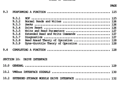
You can configure the 752 with several jumper options. '!he following subsections describe these options.
u ...- ...- ~
c
i
i
~·
·
9
·
...Lo 4i\ ~
I
;
""
...
...
Figure 2-1. 752 - canponent Location
Rev. A. June 15, 1987 10
=
Q
..,
IL . . ,
~ f
r
•
i
w
[image:28.613.76.524.115.705.2]XYLOGICS 752 Disk Controller User's Manual
2.2.1 ~ Address Selection
Jum{:er block JA controls the base address. Table 2-1 shows how to set the jum{:ers for COInItK>n1y used base addresses. Inserting a jumper makes the 752 respond to a 0 00. that address line; removing a jumper makes the 752 respond to a 1. Connect the jumper between similar pin numbers on each block. (The 752 uses bits 1 through 3 to detennine which register is being accessed.) The 752 is an Al6 Slave, and responds to address modifier 02DH, and optionally 029H.
* *
IAICI
~
JA
• •
F E•
•
•
•
o
• •
• •
C B• •
•
A•
9•
•
8•
•
7•
•
6•
•
5•
•
4*
'!hese two pins are test points, not address jumpersFigure 2-2. Base Address JlmIper Block
Screen Label
-->
F E D C B A 9 8 7 6 5 Nidress:0100 I I I I I I I 0 I I I
0800 I I I I 0 I I I I I I
EE40* 0 0 0 I 0 0 0 I I 0 I
EEOO
0 0 0 I 0 0 0 I 0 I Io
= OUt; I = Im* Standard Factory Configuration
Table 2-1. Base Address Selection
4
XYLOOIQ; 752 Disk Controller User' s Manual
2.2.2
2.2.3
.I3W2 Reguest
.ana
.I3W2 Grant Lines'!he 752 uses the Bus Request and Bus Grant lines to become bus master. In VMEbus arbitration, there are four Bus Request/Grant levels: 0 through 3. The 752 drives one Bus Request line acoording to the jmtper scheme you choose. '!he arbiter drives the four Bus Grant In lines: BGOIN* through BG3IN*. If the 752 receives a Bus Grant, and is not requesting the bus, it passes the grant by driving the appropriate Bus Grant OUt line: BGOaJT* through BG3aJT*.
Select a request level by jrmpering one Bus Request (BRO* through W*), one Bus Grant In, and one Bus Grant Out line to match the selected request level. Jrmper the remaining Bus Grant
In/0Ut
lines so that the incaning signal passes through the board (i.e., jumper BGxIN* to BGXOUT*, where
x
represents the remaining grant levels).For example, Figure 2-3 shows the jrmpering scheme for level 3 (Figure 2-3A shows the jumper blocks as they actually appear on the board 1 2-3B is labeled for this example): jrmper JB4 to JB81 then jrmper JC4 to Jes, and JD4 to JD8. Jmtper the remaining Grant levels fran JC5 to JOl, JC6 to J02, and Jc:1 to JD3. Factory oonfiguration: Bus Request Level 3.
Certain processors (i.e., Sun Microsystens) only support Bus Request Level 3.
-0- -0- -0-
-1--2- -1--2- -1--2-
-3-SR OUT IN
L BG-.J
Figure 2-3A. Actual Board Layout
BUS RQST BGOUT BGIIN
1-
se
1-
se
~~~ ~
~.,.~
.,.
~~~
JB JC
1.e.la
o
1
2 3
Figure 2-3B. Sample Jumpering Scheme
Figure 2-3. Jl.IIIpering Bus Request and Bus Grant Levels
Parallel Arbitration
If you are using the 752 in parallel arbitration, and the Bus Grant
OUt lines must be isolated fran the next slot' s Bus Grant In lines, remove all jrmpers between JC 5-8 and JD 1-4.
XYLOGICS 752 Disk Controller User's Manual
2.3 MAINTfNANCE l-DDE LOCKOOT JUMPER
Installing jumper JE 1-2 gives you unrestricted use ot the maintenance mode.
When jumper JE 1-2 is removed, you may only execute the diagnostic portion of the maintenance mode. ('!he non-diagnostic portion of the maintenance mode is proprietary to Xy10gics and subject to change without notice.)
2.4 SELF TEST DISABLE
When jumper JE 3-4 is installed, the 752 does not execute the self test on power-up.
2. ~ PRCJot1S AND PALS Location
DB
L3
M3 D2
E2
lm:t Number
180-002-173 181-001-015 181-001-016 181-001-017 181-001-041
'!ype
EPRCM
PAL PAL PAL PAL
Table 2-2. PRG1 / PAL Part Number and Location
2.6 LIGHT EMIT1'IN3 DIODES
The 752 has two light emitting diodes (LEOs). IJ. (BSY) is the Busy
LED 7 when lit, the 752 is active. L2 (ERR) is the Error LED.
During power-up, L2 lights for a manent (indicating the self test is running), and goes off 7 if L2 stays on, a fatal error occurred. 2.7 BOMID LABELS / REVISION CCNIRCL
All Xy10gics controllers use various revision control labels. This information is important when discussing configuration issues with us. P.Lease familiarize yourself with your board revision levels before contacting us.
752-101-01
Product 1 1 1
Cmfiguration
_ I
1_
Revision LevelXYLOOICS 752 Disk COntroller User I s Manual
2.8 PREPARIOO mE CCJmJTER SYSTEM FOR INsrALLATION
2.8.1
2.8.2
2.8.3
'!be backplane of your systan must provide a VMEbus slot for the 752. The slot must be capable of handling a bus master, and the power source must handle the power consumption of the entire systan, including the 752.
BacKplane Jmqpers
Remove any jumpers that short, or cause the Interrupt Acknowledge (IACK IN/OOT) and rJ.1A Grants (BG 0-3 IN/OOT) to ~s the slot in which you are installing the 752.
'!he card cage must have a slot at the proper rJ.1A priority available for the 752. The 752 uses rJ.1A to transfer data and IOPBs. Placement of the 752 in the rJ.1A priority chain may be critical.
The amount of bus bandwidth it uses will be high at times; this may affect other boards in the systan. Likewise, other boards may not al10tl enough time for the 752 to rJ.1A enough data to keep up with the disk; consider this when choosing a slot. If the 752 does not get a high enough priority, then its rJ.1A falls behind what the disk requires, and it has to wait until the next revolution before continuing the transfer. If the 752 priority is high, it gets enough rJ.1A time, but other boards having insufficient buffers may starve fran lack of IJo1A time. The priorities must be balanced for your systan to work properly.
Power Considerations
'!he 752 affects the power consumption of the entire computer systan. '!be 752 uses +5 volts for logic and -12 volts to provide -5 volts to power the differential drivers/receivers for the SMD interface. Be sure the power supplies can handle the entire power load. Readjust the voltages after plugging in the 752. A power supply that is just adequate may cause intermittent and unusual problems due to noise generated
b¥
occasionally going into overcurrent protection.L:imits: +5 volts (4.75 to 5.25 volts) at 4.1 amps; -12 volts (-li.4 to -12.6 volts) at 0.6 amps.
XYLOOICS 752 Disk Controller User I s Manual
2.9 PREPAR:m; '!HE DISK DRIVE FOR INsrALLATION
2.9.1
2.9.2
2.9.3
2.9.4
Follow the manufacturer I s instructions for Wlpacking and inspecting the disk drive.
Configure the drive for use with the 752. '!his entails setting up such parameters as the Wlit select, number of sectors per track, and ensuring the sector and index pulses are provided on the "A" cable. Consult the drive manual for the exact method of configuring your drive.
Drive Dni.t Select
A plug on the front of the drive, or switches on one of the drivels internal circuit cards, usually selects the drive Wlit number. '!he 752 accesses drives with unit numbers ranging fran 0 through 7. set the first drive to Unit O.
Number .Qf Sectors ~ Track
SWitches on one of the drive's internal circuit cards usually select the number of sectors per track. The 752 standard format uses 88 bytes of overhead per sector. 'Ibis is a naninal number derived fran the defaults set at the factory.
see
Section 8.2 for a more detailed description.If you are using the sector slip feature, the number of sectors available to the program is the total number of physical sectors on the drive less the spares (see Section 8.3 for more information on media defect mapping) •
Many disk drives have a rtmt sector (a very small sector at the end of the disk). '!he 752 requires that all sectors except the rWlt are formatted. '!he minimum runt size is six bytes.
Sector .and Index Pulses
Both the "An (Centrol) cable and the "B" (Radial) cable can provide the sector and index pulses. Disk vendors usually provide drives with sector and index on the "A" cable. '!he 752 requires the "A" ccilile to carry sector and index.
sane
disk drives use the spare lines (see section 10) forXYLOOICS 752 Disk Controller User I s Manual
2.9.5 Extended Ql1inder Addressing
.[here are two methods for addressing cylinders beyond 1023. Xylogics supports the method that uses the spare lines on the nAn
cable as cylinder address bit 10. (The 752 does not support the alternate method of USing the upper bits of the oamnon interface tus and Tag 2 [Head Tag] .)
2.10 INITIAL TEE'lS
'Ibis section relies upon your familiarity with yOW; canputer systan I s monitor and diagnostics.
2.10.1 POIrIer-lIP.ana .self ~
The 752 initiates a self test upon power-up. 'Dle Error LED (L2) lights for a manent, and then goes off. If L2 remains on, the board is not fW'lctioning properly (the Fatal Error Register may indicate the nature of the problan). When L2 is on, SYSFAIL is asserted on the VMEtus. Contact Xylogics for further assistance.
(Clleck the power supply voltages to ensure they are within limits [4.75 to 5.25 volts, and -11.4 to -12.6 volts]).
2.10.2 Drive Re~
Spin the drive up and wait for it to become ready. Issue a Read Drive Paraneters canmand. The Drive Status byte indicates the drive status at execution time. If DRDY is clear, recheck the drive cable oonnections and try again. If you are still tmable to get the proper status, check the -12V supply on the tus. If the problan persists, check the disk drive with an off-line tester. 2.11 DDGl>STICS
When you run your diagnostics:
o Format the disk with either a diagnostic or format program. o Rml a full pass of your diagnostic (or determine that the systan
is working properly).
o Cable and test any additional drives.
m.oolQ; 752 Disk Controller User I s Manual
~RE 3: '!BE 752 REGISTERS
3.0 GENERAL
'lhe 752 programming interface is based on the use of seven, one-byte long, I/O registers. 'lhe ws address jumpers define the
base address of the register set. Table 3-1 lists the registers along with the address offset fran the base address. '!he 752 responds to either bytes or l6-bit words; when it responds to words, only 8 bits are valid.
'lhe registers have one flD1ction when read, and another when written. '!be following subsections detail their definitions.
Register Offset
lOEB Address Byte 0 (Least Significant Byte) 1
10PB Address Byte 1 3
10PB Address Byte 2 5
10PB Address Byte 3 (Most Significant Byte) 7
10PB Address Modifier 9
Centrol and status Register B
Fatal Error Register D
Table 3-1. Register Offsets
3.1 10PB ADDRESS REGISTERS
The first four registers define the 32-bit address of an 10PB or
lOPB chain. When these registers are written, the 752 interprets it as the address of the 10PB or lOEB chain to be executed. When read, and the Ranove lOEB (RIO) bit is set, the registers point to the lOEB or lOPS chain just completed by the 752.
The protocol for reading and wri ting this address register is defined by the use of the Add 10PB (AIO) and Ranove lOPB (RIO) bits in the Control and Status Register (see Section 3.3).
3.2 lOPB ADDRESS K)DIFIER
X!LOOlCS 752 Disk Controller User's Manual
3.2 lOPS ADDRESS M)DlFIER (continued)
Section 3.3 defines the protocol for reading and writing this register.
IOPB ADIlmES M)DlFIER
---,---1
71
61
51
41
31
21
1101
---RESER\1ED _ _ _ _ _ _ _ _1_1
1
1
1
1
1
1
ADIlmES M)DlFIER
1_1_1_1_1_1
Bit Mnemonic Description
RESERVED. 7-6
5-0 AM ADDRFSS M)DlFIER - Most systems use the standard AM code of 3D. (See the VMEbus Specification.)
3.3 CCNlRCL AND STA'lUS RmISTER
When written, this register provides the host with control of the 752 operation 1 when read, it provides the host with 752 status information. Section 3.3.1 defines the bits in this register when written1 Section 3.3.2 defines the bits when read.
3.3.1 Control Register (Write)
aHmCL RmISTER (Write)
---_.---
-7 615 1 4 1 3 1 2 1 0
ROOISTER MAlN.rENANCE M)DE _ _ _ RESERVED _ _ _ _ _ _ _ _ _ _ _ _
mABLE MAINTENANCE M)DE _ _ _ _ _ _ RESERVED _ _ _ _ _ _ _ _ _ _ _ _ _ _ _ _ CCNlRCLLER RESET _ _ _ _ _ _ _ _ _ _ _ _ _ _ ADD lOPS _ _ _ _ _ _ _ _ _ _ _ _ _ _ _ _ _
~RIO ________________________ __