Optimization study for BNCT facility based on a DT
neutron generator
INTRODUCTION
Boron Neutron Capture Therapy (BNCT) is an effective and promising treatment of tumor
types which are resistant to conventional therapies. BNCT is a binary treatment modality,
irst a 10B compound is delivered to the patient
and differently accumulates in cancer cells versus healthy tissue; then, when a high boron
concentration ratio between tumor and healthy tissue is reached, the patient is irradiated with neutrons inducing the 10B(n,α)7Li reaction. The
have high Linear Energy Transfer (LET), and an associated high Relative Biological Effectiveness (RBE). The mean free path is about 7 μm and 4 μm for α particle and for 7Li, respectively. Considering that the mean cellular diameter is almost in the same order of magnitude, the BNCT technique may therefore be effective in selective tumor cell destruction (1, 2).
Due to their poor tissue penetration, thermal neutrons are only applicable to the direct treatment of tumors which are located near the
tissue surface. Epithermal neutrons with an
J.G. Fantidis
1*, A. Antoniadis
21Department of Electrical Engineering, Technological Education Institute of Eastern Macedonia and Thrace, Saint
Loucas, Kavala, Greece
2Cardiovascular Division, Brigham and Women's Hospital, Harvard Medical School, Boston, USA
ABSTRACT
Background: A Boron Neutron Capture Therapy (BNCT) facility, based on a DT neutron generator, with the final goal to find out a poten al, alterna ve, solu on to exis ng BNCT treatment facili es which are based on nuclear reactors is examined. Materials and Methods: With the aim of the MCNP4B Monte Carlo code different beam-shaping assembly (BSA) configura ons were considered. Lead was selected as reflector material while CF2, D2O,
Fluental, PbF4, PbF2, BiF3, BiF5, MgF2, Al2O3, AlF3, TiF3, BeD2, CaF2 and 7
LiF were examined as spectrum shi3ers. In order to improve the quality of the beam tanium, nickel-60, iron and tanium alloy (Ti6Al14V) were simulated as fast
neutrons filters while lead and bismuth were considered as gamma filters.
Results: An extensive set of calcula ons performed with MCNP4B Monte Carlo code have shown that the combina on of 7LiF which accommodates a conic part made of D2O, then followed by a TiF3 layer is the op mum
moderator design. The use of three different materials for further reduc on of fast neutrons, thermal neutrons and gamma rays is necessary. 60Ni, Cd and Bi were chosen respec vely for these purposes. The epithermal neutron flux obtained at the beam exit window turned out to be 3.94×10⁹ n cm-2 s-1 while fulfilling all the recommended IAEA in-air Figure Of Merit (FOM) criteria. The assessment of the dose profiles in head phantom and the in-phantom FOM are also presented. Conclusion: The proposed assembly configura on may provide an a>rac ve op on for centers wishing to install a BNCT facility.
Keywords: BNCT, DT neutron generator, epithermal neutron, MCNP.
* Corresponding author:
Dr. J.G. Fantidis,
Fax: +30 2510 462315
E-mail:[email protected]
Revised: April 2014 Accepted: Sept. 2014
Int. J. Radiat. Res., January 2015; 13(1): 13-24
► Original article
DOI: 10.7508/ijrr.2015.01.002
penetrating and able to reach deep-seated tumors. A typical example is glioblastoma
multi-form a quite aggressive type of brain cancer, by far the most common and malignant of the glial tumors. The application of the BNCT technique
in clinical trials requires a neutron beam having a high enough lux level and, mainly, a proper spectrum shape. In order to reduce the irradia-tion time, the desirable minimum beam intensity should be 1×109 cm-2s-1. In order to limit the treatment time to reasonable levels (i.e. 1 hour) the requested epithermal neutron lux level should be at least 109 s-1, and also well collimat-ed to avoid excessive dose to adjacent healthy tissues (3-5).
A number of candidate neutron sources for BNCT technique can be considered. Neutrons
may be generated by nuclear reactors, accelerator-driven systems or generators based
on either spontaneous ission of transuranic heavy materials, or exploiting speci ic nuclear reactions induced by radioactive sources. Radio-isotope sources, such as 252Cf and 241Am/Be are commonly used for detector calibrations because of low yield and energy up to 10 MeV. Nuclear reactors provide high-intensity neutron beams but are very expensive and considerably
sizeable to be used in hospital settings. Additionally, safety and authorization concerns
prevent their installation in urban hospitals. Accelerator-driven systems, based on linacs, cyclotrons, or tandem van de Graff may instead be properly used to yield and tailor an epither-mal neutron beam for this purpose. Their cost is generally lower compared to even small research reactors, although they need a series of ancillary systems which may occupy large space
(6-8).
DT neutron generators, based on the fusion reaction 3H(d,n)4He, may be an attractive choice as they warrant high safety, smaller size and high social acceptability. Furthermore, these neutron sources require low energy deuteron beam (100–400 keV) which is available with smaller, simpler, electrostatic-type accelerators. Last but not least they offer an on/off switching of the emitted neutrons and are less costly. A number of studies on the use of DT neutron generators for BNCT were recently published
(4, 5, 9-12).
The main goal of this study was to optimize a BNCT facility based on a DT neutron generator - which yields 1014 n s-1- in terms of beam shaping assembly (BSA) design (moderator, gamma ray, fast and thermal neutron ilters) and calculate
the dose in a simulated head phantom. The facility was designed using the Monte Carlo
MCNP version 4B, transport code which is suitable for gamma and neutron calculations (13).
MATERIALS
AND METHODS
Neutron source
DT tubes are based upon deuteron beams bombarding a tritiated target with the resultant yield of fusion neutrons. The neutron spectrum from the DT neutron generator, which was de-rived by Fantidis et al.(14), has been used for the purposes of this paper. In order to minimize the treatment time in BNCT the epithermal neutron lux has to be suf iciently high (≈109 n cm-2 s-1). According to Rasouli et al.(11) a ission-converter
-based sphere made by natural uranium surrounding the DT source target could be used
as neutron multiplier and energy degrader device in order to increase the number of neutrons via ission reaction. Based on results from the MCNP4B calculations, the ratio of neutrons yielded (mainly by ission reactions) per source neutron (N/N0), available over the surface of such a sphere, is peaked for 14 cm radius ( igure 1). These results are similar to the previous studies by Martin and Abrahantes(12) and Rasouli et al.(11).
The MCNP facility modeling
Different beam-shaping assembly (BSA) con igurations were considered, in order to ful ill the parameters required (table 1) (15). Based on the literature, lead (Pb) was selected as re lector material (8,9). Because of the high (14.1 MeV) mean energy neutrons yielded by DT reactions, a spectrum shifter system is needed in order to slow neutrons down to the required epithermal energy range (1 eV to 10 keV). In order to achieve such a goal, the "ideal" spectrum shifter should provide the following
nuclear properties: a low down scattering cross section at the epithermal energy range, high removal cross section at higher energies and limited radiative (n, γ) captures. In addition, it should not produce large quantities of gamma-rays by inelastic scattering. In order to produce an epithermal beam, the most suitable materials to moderate neutrons with different combina-tions and thickness were therefore investigated by Monte Carlo simulations. Fourteen different materials namely, Te lon (CF2), heavy water (D2O), Fluental, PbF4, PbF2, BiF3, BiF5, MgF2, Al2O3, AlF3, TiF3, BeD2, CaF2 and 7LiF were considered.
Neutrons, once being moderated pass through ilters, in order to improve the quality of neutron beam. An ideal neutron ilter must absorb only the unwanted fast and thermal neutrons without producing gamma rays. Unfortunately such nuclear properties are not
ful illed by existing materials, either in elemental or compound forms. A balanced compromise has therefore to be taken. For such a reason, the selection has been limited to four different materials able to improve the spectrum shape of the neutron beam: Titanium (Ti), Nickel-60 (60Ni), Iron (Fe) and titanium alloy (Ti6Al14V). They have proven to be effective as neutron
iltering materials aiming to improve the
Figure 1. Number of neutrons per neutron source for different thicknesses of natural uranium as a neutron
mul plier.
Table 1. Recommended values in the beam exit window.
BNCT beam port parameters Recommended value
Φepithermal (n cm-2 s-1) ~109
Φepithermal/Φfast >20
Φepithermal/Φthermal >100
Ḋfast/Φepithermal (Gy cm2) <2 × 10-13
Ḋγ/Φepithermal (Gy cm2) <2 × 10-13
Fast energy group (Φfast) E>10 keV
Epithermal energy group (Φepithermal) 1 eV ≤ E ≤ 10 keV
Thermal energy group (Φthermal) E<1 eV
epithermal to fast neutron ratio in the BNCT neutron beam. High Z materials, such as lead (Pb) and Bismuth (Bi) are instead suitable in
order to remove the gamma component. Moreover, in order to increase the epithermal to
thermal ratio materials having a high absorption cross section in thermal range are needed. An absorber material, lithiated poliethylene (poly-Li), is at last included as delimited to get a colli-mated neutron beam. The inal part of the BSA design includes a delimiter with the intention to minimize the dose rate outside of the tumor cells. It should be noted that the unit is designed in the form of coaxial cylinders and the neutron distribution is symmetrical due to the symmet-rical geometry considered.
RESULTS
A wide set of computational studies was car-ried out using the MCNP4B Monte Carlo code. The neutron lux and the dose rate were calcu-lated at the exit of the facility across the 12 cm diameter window using the F2, Fm2 tallies and the DE, DF cards. An accuracy of less than 1% was achieved in all cases. Fourteen different spectrum shifter materials to slow neutrons down to epithermal energy ranges, having
different thickness, were therefore investigated.
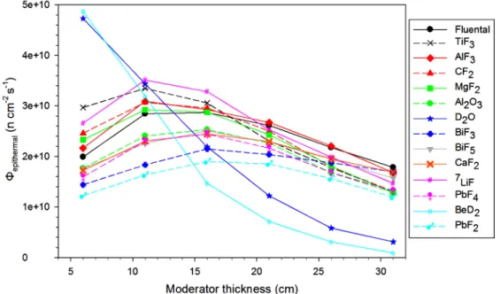
Figure 2 shows the Φepithermal for the studied materials as a function of the moderators'
thick-ness. In igure 3 the Φepithermal/Φfast ratio of spec-trum shifter candidate materials versus their thickness, is plotted. According to the results the BeD2 and the D2O give the higher Φepithermal short moderators length, although the lux level quick-ly drops off with increasing thickness. Taking into account plots in igures 2 and 3, it may be concluded that 19 cm thickness of 7LiF provides the optimal balance between Φepithermal and
Φepithermal/Φfast ratio correspondingly.
With the aim to ind out the best solution a huge number of con igurations have been considered and the simulations show that 19 cm of 7LiF housing at the beam axis an additional, truncated cone volume illed with D2O is the optimum choice. The truncated cone moderator has a length of 6 cm and radii 6 and 1 cm with the larger radius close to the source. The conic part increases the Φepithermal and the Φthermal and reduces the Φfast. Particularly the introduction of the D2O increases the Φepithermal more than 7% (3.04×10¹⁰ n cm-2 s-1 vs. 2.84×10¹⁰ n cm-2 s-1) and improves the Φepithermal/Φfast and the Φepithermal/
Φthermal by 9.89% and 0.87% respectively.
How-ever, both the Φepithermal/Φfast and the Φepithermal/
Φthermal ratios have values (2.89 and 10.49
Figure2. Φepithermal for different thicknesses of moderators.
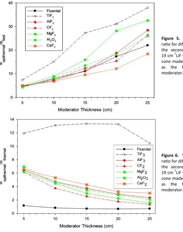
TiF3 seem to be however a better choice because of superior values for Φepithermal/Φfast and the
Φepithermal/Φthermal BSA modeling parameters.
Indeed if TiF3 is selected as spectrum shifter instead of Fluental the BSA shows to have comparable values for the Φepithermal, a better performance for the Φepithermal/Φfast ratio and by far higher values for the Φepithermal/Φthermal ratio. Therefore results revealed that the optimum thickness for the TiF3 spectrum shifter is 19 cm. correspondingly) below from the recommended
limits. For these reasons a second moderator should be used.
Figures 4, 5 and 6 show the Φepithermal,
Φepithermal/Φfast and the Φepithermal/Φthermal ratios
for a number of materials which have been selected as second spectrum shifter versus their thicknesses, whilst 19 cm 7LiF incorporating a D2O conic part has previously been selected as
the irst part of the moderator. Even though Fluental is able to provide a larger Φepithermal, the
Figure3. The Φepithermal/Φfast ra o for different thicknesses of moderators.
Figure 4. Φepithermal for different thicknesses of the second moderator where 19 cm 7LiF which incorporates a cone made of D2O are selected as the first part of the moderator.
The BSA con iguration thus selected allows for improving the quality of the in air FOM beam parameters, but the DNfast/Φepithermal (4.57×10⁻¹³ Gy cm2) and the DNγ/Φepithermal (4.01×10⁻¹² Gy cm2) ratios turns out to be above the ixed lev-els. The value of the DNfast/Φepithermal shows that the proper selections for a fast neutron ilter is required in order to optimize the BSA design. Therefore 4 different materials (Fe, Ti6Al14V, Ti, 60Ni) were examined as fast neutron ilters. In
igure 7 plots of the calculated DNfast/Φepithermal ratio for different thickness of the investigated
ilters, shows that 60Ni is a better choice. How-ever the beam spectra owing to the fast neutron
ilters show ( igure 8) that the presence of the Ti ensures higher Φepithermal with slightly lower values for the DNfast/Φepithermal ratio. Motivated by these results all the BNCT in-air FOM parame-ters have been calculated and the results are summarized in table 2. From such results it may
Figure 5. The Φepithermal/Φfast
ra o for different thicknesses of the second moderator where 19 cm 7LiF which incorporates a cone made of D2O are selected
as the first part of the moderator.
Figure 6. The Φepithermal/Φthermal
ra o for different thicknesses of the second moderator where 19 cm 7LiF which incorporates a cone made of D2O are selected
as the first part of the moderator.
be noted that the Ti ilter compared with the 60Ni provides higher Φepithermal and has slightly higher value for the Φepithermal/Φthermal ratio. However the inal choice for the fast neutron ilter is 60Ni (with thickness 5 cm) because not only presents comparable values for the Φepithermal, Φepithermal/
Φthermal, Φepithermal/Φfast and DNfast/Φepithermal but
also shows a basically lower level for the DNγ/
Φepithermal ratio. This fact is very important
because require a less thick gamma ilter with an improvement on the Φepitermal level as well, compared with Ti or 60Ni.
Table 2. The relevant with BNCT parameters for 5cm thickness of the inves gated fast neutrons filters.
Filter Φepithermal
(×109n cm-2s-1)
Φepithermal/Φfast Φepithermal/Φthermal Ḋfast/Φepithermal
(×10–13 Gy cm2)
Ḋγ/Φepithermal
(×10-13 Gy cm2)
Fe 4.31 33.07 96.30 2.60 2.11
Ti6Al14V 5.55 46.02 23.11 2.65 2.27
Ti 7.52 72.61 34.54 2.14 2.88
60
Ni 6.71 78.94 31.94 1.96 1.06
IAEA criteria >1 >20 >100 <2 <2
Figure7. The Ḋfast/Φepi ra o for
different thicknesses of fast neutrons filters.
Figure 8. The neutron spectra for 5cm thickness of the inves gated fast neutrons filters.
The Φepithermal/Φthermal ratio can be further
raised up above the recommended level by us-ing a thin layer of thermal neutron absorber. Just 0.15 cm of Cadmium (Cd) is indeed enough to absorb a large fraction of thermal neutrons with a negligible part of epithermal ones. On the contrary Cadmium has the drawback of a high energy gamma rays yield upon neutron capture but this problem may be overcome if the Cd thermal neutron ilter placed before of a gamma shield (16). Gamma rays can be attenuated by
using appropriate high-Z materials such as the Bi or Pb. Bi is commonly used, since it provides photon attenuation comparable to that from Pb, while limiting the absorption for the neutron beam. Results of comparative calculations are
summarized in table 3. Therefore 5.5 cm thick-ness Bi gamma shielding, completed by 2 cm thickness delimiter made of poly-Li is the last part of the BSA study which is shown in igure 9. Neutron spectra of the proposed facility, calcu-lated in three con igurations, without ilters, with 5 cm 60Ni fast neutron ilter and for the inal
BSA con iguration are shown in igure 10. The pro ile of the Φepithermal in front of the BSA is
shown in igure 11.
In this study the Snyder’s head phantom, which was derived by the MCNP sample iles, is simulated using MCNP4B code. This phantom consists of three ellipsoids for scalp, skull bone and brain. The dimensions and the chemical composition for an adult proceed from ICRU46
Table 3. The BNCT parameters for different gamma ray filters.
Configura7on Φepithermal
(×109n cm-2s-1) Φepithermal/Φfast Φepithermal/Φthermal
Ḋfast/Φepithermal
(×10–13 Gy cm2)
Ḋγ/Φepithermal
(×10-13 Gy cm2) 7
LiF, D2O, TiF3 moderators
+ 60Ni fast neutron filter + Cd thermal neutron filter + 5.5cm Bi
3.94 52.29 107.95 0.179 1.27
7
LiF, D2O, TiF3 moderators
+ 60Ni fast neutron filter + Cd thermal neutron filter + 4.5 cm Pb
3.53 56.70 139.18 0.241 1.90
IAEA criteria >1 >20 >100 <2 <2
Figure9. Geometric configura on of the BNCT system -not in scale.
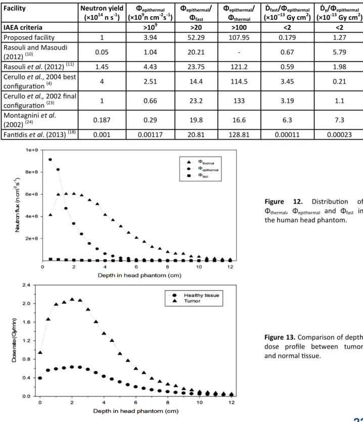
(17). The spatial distribution of the Φthermal,
Φepithermal and Φfast in the head phantom along
the beam axis for Z direction are illustrated in igure 12. According to the results the Φepithermal
and Φfast have the maximum values at the scalp
and the lux level drops off with increasing thick-ness. The maximum Φthermal occurs at a depth of
1.5 – 2.6 cm.
The total absorbed tissue doses (DT) are
obtained by combining the four individual dose components, namely gamma ray dose (Dγ), fast
neutron dose (Dfast), nitrogen dose (DN), boron
dose (DB), weighted by their RBE (relative
bio-logical effectiveness) factors, using the equation: DT = wγ×Dγ + wfast×Dfast + wN×DN + DB×wB
where wγ is 1, wN and wfast are taken as 3.2 while
wB is 1.3 for boron in tissue and 3.8 for boron in
the tumor. In the tumor, a 10B concentration of
40 ppm was assumed and a 4:1 ratio of 10B in
tumor to healthy brain was also assumed (9).
Figure 13 shows the calculated dose rates in the tumor and healthy tissues at different depth in the head phantom.
DISCUSSION
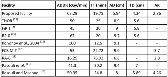
In order to evaluate the proposed facility the results are compared with other published studies which are based on DT or DD neutron generator (table 4). These results (unacceptable values are in italic letters) indicate that only 2 Figure 10. The neutron spectra at the exit of the facility with and without filters.
Figure 11. The profile of the Φepithermal in front of the
suggested BSA modeling.
facilities satisfy all the recommended by IAEA criteria; the excellent extensive research from Rasouli et al. (11) and the study are presented
which optimizes the previous BSA con igura-tions. As shown in table 4 the proposed facility
compared with the study from Rasouli et al. improves the Φepithermal/Φfast ratio by a factor of
∼2.2. At the same time reduces the DNfast/
Φepithermal and the DNγ/Φepithermal by 3.7 and 1.6
times respectively while decreasing the
Figure 12. Distribu on of
Φthermal, Φepithermal and Φfast in
the human head phantom.
Figure13. Comparison of depth
dose profile between tumor and normal ssue.
Table 4. Comparison of the proposed facility with some published works (based on DT or DD neutron generator).
Facility Neutron yield
(×1014 n s-1)
Φepithermal
(×109n cm-2s-1)
Φepithermal/
Φfast
Φepithermal/
Φthermal
Ḋfast/Φepithermal
(×10–13 Gy cm2)
Ḋγ/Φepithermal
(×10-13 Gy cm2)
IAEA criteria >109 >20 >100 <2 <2
Proposed facility 1 3.94 52.29 107.95 0.179 1.27
Rasouli and Masoudi
(2012) (10) 0.05 1.04 20.21 - 0.67 5.79
Rasouli et al. (2012) (11) 1.45 4.43 23.75 121.2 0.59 1.98
Cerullo et al., 2004 best
configura on (4) 4 2.51 14.4 114.5 3.45 0.21
Cerullo et al., 2002 final
configura on (23) 1 0.66 23.2 133 3.19 1.1
Montagnini et al.
(2002) (24) 0.187 0.29 19.8 16.6 6.3 7.3
Fan dis et al. (2013) (18) 0.001 0.00117 20.81 128.81 0.00011 0.00023
Φepithermal/Φthermal ratio by only ∼10.9%. The
comparison between the proposed facility with a similar facility which proposed by Fantidis et al.
(18) and based on DD neutron generator indicates
that the use of DT neutron generator is by far the best solution owing to the fact that DT neutron source provides signi icant higher Φepithermal
values. Considering that DT neutron generators having 1014 n s-1 neutron output may be feasible the proposed facility might be taken into account as an alternative for clinics which cannot afford to build and maintain a small nuclear reactor.
The therapeutic ef icacy of neutron beam for the proposed BNCT facility were calculated
through its FOM, i.e. Dose Rate (ADDR),
Treatment Time (TT), Advantage Depth (AD), Advantage Ratio (AR) and Therapeutic Depth (TD). ADDR is de ined as the maximum deliv-ered dose rate to healthy tissue. Bearing in mind that the maximum allowable dose to the healthy tissue is 12.5 Gy (19), the TT can be estimated. AD indicates the depth in tissue at which the dose to the tumor equals the maximum dose to the healthy tissue. AR is the integral dose that would
be delivered to tumor tissue, uniformly distributed within the brain, divided by the integral dose delivered to normal tissue, while TD de ines the depth at which the tumor dose falls below twice the maximum dose to healthy brain (11, 20-22).
The in-phantom parameters of the proposed facility and from some previous published stud-ies are listedin table 5 and show a neutron beam
which can reach relevant deeply into the brain (AD has value about 6 cm). The TT parameter which indicates the treatment time has a very attractive value (less than 20 min indicating a reasonable treatment time) as a result of the relatively high fepithermal value.
CONCLUSION
BNCT is a potentially very useful cancer treatment modality; however only a few facilities are available for clinical trials, since all these facilities are currently based on a nuclear reactor source. In order to ind an alternative source for BNCT applications a DT neutron generator has been considered, using the
MCNP4B Monte Carlo code. The proposed facility is optimized in terms of the moderator
and beam iltering. 7LiF incorporating a truncat-ed-cone-shaped made of D2O and TiF3 were chosen as the moderator materials. The use of 60Ni as fast neutron ilter, Cd as thermal neutron ilter and Bi as gamma ilter has led to improving the quality of the beam for BNCT. The resulting dose of the radiation emitted from the facility is evaluated de ining the FOM in phantom. Accord-ing to the results obtained, the proposed facility meets all the recommended by IAEA parameters and constitutes an attractive alternative to the nuclear reactors.
Con lict of interest: Declared none
Table 5. In-phantom parameters evaluated for the proposed designed BSA and some other facili es.
Facility ADDR (cGy/min) TT(min) AD(cm) TD(cm) AR
Proposed facility 63.29 19.75 5.94 4.34 2.86
THOR (25) 50 25 8.9 5.6 -
FiR 1 (25) 45 30 9 5.8 -
R2-0 (25) 67 20 9.7 5.6 -
Kononov et al., 2004 (26) 100 12.5 9.1 - -
FCB MIT (27) 55 22.72 9.9 - 5.7
RA-6 (28) 16.25 76.92 6.8 - 2.8
Rasouli et al. (11) 41.3 30.2 9.4 7 -
Rasouli and Masoudi (10) 50.35 24.8 8 5.89 4.26
REFERENCES
1. Tanaka H, Sakurai Y, Suzuki M, et al. (2009) Characteris cs
comparison between a cyclotron-based neutron source
and KUR-HWNIF for boron neutron capture therapy. Nucl
Instrum Method Phys Res B, 267 (11): 1970-1977.
2. Brockman JD, Nigg DW, Hawthorne MF, et al. (2009)
Char-acteriza on of a boron neutron capture therapy beam line
at the University of Missouri Research Reactor. J
Radio-anal Nucl Chem, 282(1): 157-160.
3. Lee D-j, Han CY, Park SH, et al. (2004) An
accelerator-based epithermal neutron beam design for BNCT and
dosi-metric evalua on using a voxel head phantom. Radiat Prot
Dosim, 110: 655-660.
4. Cerullo N, Esposito J, Daquino GG (2004) Spectrum
shap-ing assessment of accelerator-based fusion neutron
sources to be used in BNCT treatment. Nucl Instrum
Method Phys Res B,213: 641-645.
5. Dao-wen C, Jing-bin L, Dong Y, et al. (2012) Improvement
of the moderator’s thermaliza on efficiency for 14 MeV
neutrons in boron neutron capture therapy. Radioanal
Nucl Chem, 292(3): 1085 -1088.
6. MacGillivray G (2000) Imaging with neutrons: the other
penetra ng radia on. Nray Services Inc. Proc. SPIE, 4142:
48-57.
7. Bisceglie E, Colangelo P, Colonna N, et al. (2002)
Produc-on of epithermal neutrProduc-on beams for BNCT. Nucl Instrum
Method Phys Res A, 476: 123-126.
8. Durisi E, Zanini A, ManfredoV C, et al. (2007) Design of an
epithermal column for BNCT based on D–D fusion neutron
facility. Nucl Instrum Method Phys Res A, 574(2): 363-369.
9. Koivunoro H, Bleuel DL, Nastasi U, et al. (2004) BNCT dose
distribu on in liver with epithermal D-D and D-T
fusion-based neutron beams. Appl Radiat Isot, 61(5): 853-859.
10. Rasouli FS and Masoudi SF (2012) Design and op miza on
of a beam shaping assembly for BNCT based on D–T neu-tron generator and dose evalua on using a simulated
head phantom. Appl Radiat Isot, 70(12): 2755 - 2762.
11. Rasouli FS, Masoudi SF, Kasesaz Y (2012) Design of a
mod-el for BSA to meet free beam parameters for BNCT based,
on mul plier system for D–T neutron source. Ann Nucl
Energ, 39: 18 - 25.
12. Mar n G and Abrahantes A (2004) A conceptual design of a beam-shaping assembly for boron neutron capture
ther-apy based on deuterium-tri um neutron generators. Med
Phys, 31: 1116-1122.
13. Briesmeister JF (1997), MCNP4B MCNPTM–A General Monte Carlo N-par cle transport code, version 4B LA-12625-M Manual.
14. Fan dis JG, Nicolaou GE, Potolias C et al. (2011) The
com-parison of four neutron sources for Prompt Gamma Neu-tron Ac va on Analysis (PGNAA) in vivo detec ons of
Boron. J Radioanal Nucl Chem, 290(2): 289-295.
15. IAEA-TECDOC-1223 (2001) Current status of Neutron Cap-ture Therapy, Interna onal Atomic Energy Agency. 16. Sakamoto S (1997), Sensi vity Studies of the Neutronic
Design of a Fission Converter-Based Epithermal Beam for Boron Neutron Capture Therapy, Ph.D. Thesis, Massachu-se>s Ins tute of Technology.
17. ICRU46 (1992), Interna onal Commission on Radia on
Units and Measurements.
18. Fan dis JG, Sai o E, Bandekas DV, et al. (2013) Op-mised BNCT facility based on a compact D-D neu-tron generator. Int J Radiat Res, 11: 207-214.
19. Kim K-O, Kim JK, Kim SY (2009) Op mized therapeu c
neutron beam for accelerator-based BNCT by analyzing
the neutron angular distribu on from 7Li(p,n)7Be reac on,
Appl Radiat Isot, 67: 1173-1179.
20. Kiger WS, Sakamoto S, Harling O (1999) Neutronic Design
of a Fission Converter-Based Epithermal Neutron Beam for
Neutron Capture. Therapy. Nucl Sci Eng, 131(1): 1-22.
21. Elshahat BA, Naqvi AA, Maalej N, et al. (2007) Design
cal-cula ons of an accelerator based BSA for BNCT of brain
cancer. J Radioanal Nucl Chem 274(3): 539-544.
22. Sakamoto S, Kiger WS, Harling OK (1999) Sensi vity
stud-ies of beam direc onality, beam size, and neutron spec-trum for a fission converter-based epithermal neutron
beam for boron neutron capture therapy. Med Phys, 26
(9):1979-1988.
23. Cerullo N, Esposito J, Leung KN, et al. (2002) An irradia on
facility for Boron Neutron Capture Therapy applica on based on a radio frequency driven D–T neutron source and
a new beam shaping assembly. Rev Sci Instrum, 73:
3614-3618.
24. Montagnini B, Cerullo N, Esposito J, et al. (2002) Spectrum
shaping of accelerator-based neutron beams for BNCT.
Nucl Instrum Method Phys Res A, 476: 90-98.
25. Liu YW, Huang TT, Jiang SH, et al. (2004) Renova on of
epithermal neutron beam for BNCT at THOR. Applied
Radi-a0on and Isotopes, 61: 1039–1043.
26. Kononov OE, Kononov VN, Bokhovko MV, et al. (2004)
Op miza on of an accelerator-based epithermal neutron
source for neutron capture therapy. Appl. Radiat. Isot,
61:1009–1013.
27. BinnsPJ, Riley KJ, Ostrovsky Y, et al. (2007) Improved Dose
Targe ng for a Clinical Epithermal Neutron Capture Beam
Using Op onal 6Li Filtra on.
Int J Radiat Oncol-Biol-Phys,
67 (5): 1484–1491.
28. Calze>a L, Blaumann O, Longhino HR, et al. (2001) BNCT
facility at the RA-6 reactor, Current Status of Neutron Cap-ture Therapy, IAEA-TECDOC-1223, VIENNA.