A Modi
fi
ed Shared-tree Multicast
Routing Protocol in Ad Hoc Network
Ziping Liu
1and Bidyut Gupta
21Computer Science Department, Southeast Missouri State University, Cape Girardeau, USA 2Department of Computer Science, Southern Illinois University, Carbondale, USA
A mobile ad hoc network is a wireless mobile network that does not have any base station or other central con-trol infrastructure. Design of efficient multicast routing protocols in such a network is challenging, especially when the mobile hosts move rapidly. Shared-tree routing protocol is a widely used multicast routing protocol in ad hoc networks. However, this protocol is deficient in terms of the end-to-end delay and network throughput. In this paper, we propose a protocol to improve the inherent problem of the large end-to-end delay in the shared-tree method as a modification to the existing multicast Ad hoc On-demand Distance Vector(MAODV)routing for the
low mobility network. The protocol uses the n-hop local ring search to establish a new forwarding path and limit the flooding region. We then propose an extension to our proposed protocol, by using the periodic route discovery message to improve the network throughput for the high mobility network. Simulation results demons trate the improvement in the average end-to-end delay for the low mobility case as well as in the high packet delivery ratio for the high mobility case.
Keywords: ad hoc network, multicast routing protocol,
end-to-end delay, packet delivery ratio.
1. Introduction
Multicast is a technique which uses one sending operation to deliver data to a group of interested receivers. Data are only delivered to interested hosts. Links, which are connected to uninter-ested hosts do not carry traffic unless such hosts are on the path from the sender to the interested receivers. Thus, multicast provides the most ef-ficient use of resources and it is becoming more popular, especially in internet multimedia en-tertainment applications, such as audio/video
conference. In wired networks, there are gener-ally two basic approaches for multicast routing: shared-tree routing and source-specific routing.
Shared-tree routing constructs a single tree that is shared by all members of the group. Mul-ticast traffics for the entire group are delivered along the edges of this unique tree, regardless of the source. The center-based approach 1]
is one such method and the rendezvous point is selected in advance to try to optimize network traffics. The second approach relies on flooding to propagate information to all network routers, and various sources construct their own multi-cast trees. Thus, packets from different sources are delivered along different tree edges. Source-specific approaches include DVMRP 2],
MO-SPF3]and PIM-DM4].
Source-specific routing protocols rely on the periodic flooding of messages throughout the network and the aggregate traffic from this pe-riodic flooding could potentially saturate net-work connections. Compared with source-spe-cific tree, the use of a shared-tree can provide significant savings in terms of the amount of multicast state information that is stored in in-dividual routers. Thus, shared-tree routing may perform very well for large numbers of low data rate sources.
etc. The characteristics of mobile ad hoc net-works are: (1)Unlike the single hop(i.e.
cel-lular) network, an ad hoc mobile network has
neither fixed base stations nor a wired back-bone. So multihop over several mobile hosts may be required for communication; (2)
Re-sources such as storage capacity and battery power of any mobile host, as well as channel bandwidth, are limited; (3)Network topology
changes frequently and unpredictably. All these constraints make routing and multicasting ex-tremely challenging. Traditional IP multicast protocols, such as DVMRP, MOSPF, CBT and PIM are efficient in wired networks. However, these protocols cannot achieve the same effi-ciency in ad hoc networks.
Ad hoc multicast protocols have recently at-tracted a lot of attention in the research commu-nity. There are two general approaches: mesh-based multicast routing, such as ODMRP5,
6], and tree-based multicast routing, such as
MAODV7, 8, 9]. ODMRP is claimed as robust
in data delivery ratio, but it has the broadcast storm problem that severely impacts its perfor-mance. In MAODV, the shared tree is initiated and maintained by a multicast group leader. The group leader/tree root is selected as the node,
which is the first one to send data to its multicast group members. Such selection criteria cannot optimize the network and is different from wired network’s center-based approach, in which the rendezvous point is selected in advance to opti-mize network traffic. In shared-tree approach, when a node other than the multicast group leader wishes to send data packets, it can send its data packets immediately along the unique tree edges. Accordingly, a shared tree would con-serve network resources such as channel over-head and bandwidth, because it doesn’t invoke any new route discovery.
Shared-tree method is efficient in static and low mobility ad hoc networks. However, it may increase the end-to-end propagation delay if nodes, which are far away from the existing tree root node, wish to send packets to its multicast group. The problem can be severe when the network is large and sparse, especially for real time applications such as audio/video, which
are time/delay sensitive. In the high mobility
ad hoc network, the existing shared-tree method such as MAODV also encounters low packet delivery ratio due to the frequent network topo-logical change. Our goal in this work is to
overcome such disadvantages of the shared-tree method and to make it more robust in both the low and high mobility ad hoc networks. The first part of our work is to explore a new ap-proach to reduce end-to-end delay. In an ad hoc network of the shared-tree method, a sender node, or some intermediate router node, may have links with other multicast tree nodes, but these links may not belong to the multicast tree edges. We call this type of links “potential com-munication links”. If “potential comcom-munication links” are used to deliver packets, the packet end-to-end propagation delay can be reduced for some of the multicast group receivers. Fur-thermore, our new approach makes intelligent use of the existing shared tree to localize the query flooding to a limited region in the net-work. The second part of our work is about how to improve packet delivery ratio for high mobility ad hoc network. By reduction of end-to-end delay and query flood, and by improve-ment of data delivery ratio, our approach can deliver comparable performance advantages. In this work, we will apply two techniques to the well-studied multicast ad hoc routing pro-tocol MAODV. We refer to the new propro-tocol as the Modified Shared-tree Multicast Routing Protocol (MSMRP). The primary design goal
behind MSMRP is to improve the end-to-end delay in the shared-tree method. To achieve this, MSMRP uses the n-hop local ring search to create new forwarding tree branches based on the existing multicast tree. A special “Forward-ing Query” message is used locally to activate the potential communication links. Such tech-nique can also be applied to other shared-tree methods such as LAM10]. In order to improve
the packet delivery ratio, even in the high mobil-ity network, MSMRP further uses the periodic control message to establish and maintain up-to-date routes for a multicast group.
2. Ad Hoc On-demand Distance Vector Routing
AODV integrates unicast and multicast in one protocol and multicast AODV is referred to as MAODV. It uses destination sequence numbers in DSDV11]with the on-demand route
discov-ery technique in DSR12]to formulate a pure
on-demand, loop-free routing protocol. Unlike DVMRP, which uses “broadcast and pruning” to form multicast tree, MAODV uses receiver’s reply message to add multicast branch. Below, we review some of the key features of MAODV.
2.1. Routing Table
In MAODV, each node on the multicast tree has its own Multicast Route Table(MRT)to
main-tain the multicast tree and deliver data packets. The fields of the MRT are as follows:
Multicast Group IP Address
Multicast Group Leader IP Address Multicast Group Sequence Number HopCount to Multicast Group Leader Next hops, with the following data per hop:
Next Hop IP Address Link Direction Activated Flag
In the multicast routing table mentioned above, group sequence number is used to keep an up-to-date group information. The link direction of a next hop is defined to be upstream if the link is towards the group leader, and downstream if it is away from the group leader. There should be at most one upstream link at any time. The ac-tivated flag associated with each next hop is an indication of whether the link has been officially added to the multicast tree.
2.2. The Group Leader
In MAODV, the group leader is selected as the first node, which wishes to send data packets to a multicast group.
2.3. Route Discovery
A node sends a Route Request (RREQ)
mes-sage when it wishes to join a multicast group, or when it has data to send to a multicast group and it does not have a route to that group. If the RREQ is a join request, only a node that is a member of the desired multicast tree, or a node with a current route to the multicast group, may respond. Otherwise, it just broadcasts the RREQ to its neighbors. When a node receives a join RREQ for a multicast group, it may reply if it is a router for the multicast group’s tree and its recorded sequence number for the multicast group is at least as large as that contained in the RREQ. The node then unicasts the Route Reply
(RREP) message to the node indicated in the
RREQ. As nodes along the path to the source node receive the RREP, they set up a forward path entry for the multicast group.
2.4. Route Activation
When a source node broadcasts a RREQ for a multicast group, it often receives more than one reply. In MAODV, source node keeps track of the route with the largest multicast group se-quence number and the smallest hop count to the multicast tree. At the end of the discovery, it activates that route by unicasting a multicast activation(MACT)message to its selected next
hop. Once the next hop receives this message, it activates the route and, if it was not the origina-tor of the RREP, sends its own MACT message to its next hop. This continues until the origi-nator of the RREP is reached. At that point, the new path to the multicast tree has been deter-mined.
2.5. Multicast Message Forwarding
hop, except that neighbor from which the mes-sage has arrived. If there are multiple next hops, the forwarding operation may be performed by broadcasting the multicast packet to the node’s neighbors; only the neighbors that belong to the multicast tree and have not already received the packet continue to forward the multicast packet.
3. Shared-tree Problems in Ad Hoc Network
3.1. Problem I: shared-tree long delay
We first present shared-tree long delay problem in 13]. In low mobility or static ad hoc
net-works, network topology is relatively stable and group-shared multicasting, such as MAODV, is simple to implement and maintain once the shared tree is formed. Usually, the shared tree lasts for the lifetime of a multicast session. Whenever a node wishes to send data packets to its group members, it can make full use of the existing shared tree. In this way, a sending node can avoid extra computation and conserve its resources, such as battery energy.
In MAODV, the shared tree is initiated and maintained by the first node, which wishes to send data to a multicast group. The node is then chosen as the group leader/tree root. Such
se-lection criteria are different from the wired net-work, where the rendezvous point is selected to optimize the multicast traffic, and is determined in advance. Due to the randomness and mobility of an ad-hoc network, this kind of pre-selection procedure cannot be performed. In shared-tree approach, if other source nodes wish to send
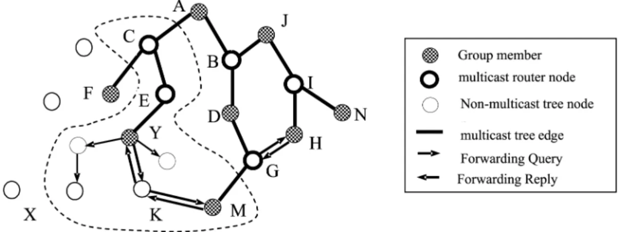
data packets to the group, packets are delivered over its unique multicast tree edges. In case new sending source nodes being close to the root node, packet propagation delays are not impacted significantly. In case source nodes are far away from root node, end-to-end prop-agation delay is elongated. For time sensitive application such as audio or video conferencing, time delay cannot be neglected. In a medium or a large multihop wireless network, the elon-gation is even bigger. Moreover, in wireless network, the longer a packet travels, the higher is the probability of packet loss or error rate. Figure 1 shows an example of this observation. In this example, A is the group leader/root node
and linkYKMdose not belong to the shared tree. Suppose node Y initiates a new sending opera-tion, its packets then travel over those solid lines in MAODV. It is obvious that packets arriving at M must travel all the way through E, C, A, B, D, G, even though the distance between Y and M is just 2 hops. Other nodes such as D, H, etc. can be affected as well.
3.2. Geometric Model Analysis
In order to explain the above observation more clearly, let us analyze two abstract geometric models. The first model is a triangular topol-ogy, in which the group leader is at one corner, as shown in Figure 2. Assume node A is the group leader. Further, assume that the network diameter, which is the maximum of all mini-mum distances between any two nodes, isd. If mobile hosts in the network move very slowly,
we can also assume that the network topology remains unchanged during any specific period of time. If pure shared-tree approach is used to route data packets, we have:
End-to-end delayBtoC / 2d
End-to-end delayDtoC / 1:5d
End-to-end delayEtoC / d
Fig. 2.A Triangular Shared-Tree Network.
If potential communication links in Figure 2 are active, then:
End-to-end delayBtoC / d
End-to-end delayDtoC / d 0
End-to-end delayEtoC / d 00
Sinced0
<d,d 00
<d, we have:
End-to-end delayBtoC / d
End-to-end delayDtoC / d
End-to-end delayEtoC / d
The above analysis indicates: potential com-munication links can significantly decrease the end-to-end delay of nodes, which are far away from the root node in triangular shared-tree net-work.
Fig. 3.A Star Shape Shared-Tree Network.
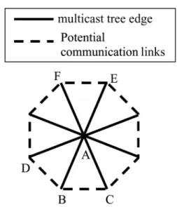
The second shared-tree model is a star shape one, in which group leader A is located at the center of the star, as shown in Figure 3. In this case, if a node, which is far away from the group leader, such as node B, sends data packets, the end-to-end delay of nodes (i.e. between C and
B, and between D and B), which are
geographi-cally close to the new source node, such as B, are significantly decreased. The end-to-end delay of nodes(i.e. between E and B, and between F
and B), which are geographically far away from
the new source node, such as B, is not affected too much.
The above geometric analysis indicates that po-tential communication links can decrease the end-to-end delay for nodes which are far away from the group leader and are geographically close to the new source node. In section 4, we will explain how the potential alternate links can be activated to avoid “detour” and speed up packet delivery with respect to a new source node. In our first proposed method, a new for-warding tree is formulated via the primary tree edges and the potential communication links. This can limit network-wide message flooding and hence avoids the common broadcast storm problem in source-based method.
3.3. Problem II: low throughput of
shared-tree in high mobility network
In a low mobility ad hoc network, the network topology remains relatively stable. Therefore link breakage due to the change of the network topology does not occur frequently. Occasional broken link repairs can meet the demand of the network maintenance. In MAODV, when a link breaks, the downstream node of the break is responsible for repairing the link. The down-stream node initiates the repair by broadcasting a joint RREQ. A node on the multicast tree re-sponds to the RREQ by unicasting a RREP back to the initiating node. Subsequent route activa-tion is handled as described in Secactiva-tion 2. The above repair procedure is not efficient in a highly dynamic ad hoc network. In a highly dynamic ad hoc network, nodes move faster and thus can quickly move out of their prior trans-mission range. This will cause communication link to break frequently. Hence, receiver-driven route discovery will happen very often. When a node loses its prior communication link, the node itself and all of its downstream member nodes flush away their current routing table and initiate the route repair procedure. In a high mobility network, it is possible that a number of communication links break at the same time. Therefore, a number of member nodes may ini-tiate new route discovery simultaneously. Such behavior can invoke too many joint RREQs to be flooded within the network. It also causes in-crease in control traffic for the network and can further causes channel contention and network congestion. In our second proposed method, we use periodic RREQ originated from the source node, to avoid the above shared-tree problem and improve the network throughput.
4. Modified Shared-tree Multicast Routing Protocol
With the above shared-tree problems in mind, we propose two protocols to reduce average end-to-end delay and packet delivery error rate for low mobility network and high mobility net-work respectively. We call these two protocols modified shared-tree multicast routing protocol
(MSMRP) and modified shared-tree multicast
routing protocol extension(MSMRPx),
respec-tively. Before the protocols are presented, we
introduce the following concepts which will be used in designing the protocols to reduce the end-to-end delay and improve the packet deliv-ery ratio.
4.1. Exploiting New Route Discovery
In a multicast session, various group members may become source nodes and send their data packets to other members in the same group. From Section 3 we know that in the shared-tree method, when a source node, which is far away from the group leader, sends data packets to its multicast group, it may take more time for packets to arrive at their destination receivers. Hence, we exploit new route discovery in our first proposed protocol as follows:
If a node wishes to send multicast data pack-ets to its multicast group and this node is close to the existing shared-tree root node, it delivers its data packets along the original shared-tree;
If a node wishes to send multicast data pack-ets to its multicast group and this node is far away from the existing shared-tree root node, it initiates a new route discovery. Figure 1 illustrates the above concept with an example network. Node Y in this network is a leaf node and is far away from the group leader. When this member node wishes to send its data packets to the multicast group, it initiates a new route discovery. However, for member node J that is close to group leader A, it will just send its data packets along the existing shared tree edges when it wishes to send data.
4.2. Concept of Forwarding Path
a)Entire Region b)Corner Region c)Partial Region.
Fig. 4.
4.3. Concept of Spatial Locality Flooding
For static or low mobility networks, a mobile host usually will not move too far away from its previous location during a specific length of time. So, when a new source node has data to send to the existing multicast group and ex-ploits the new route discovery, the discovery re-gion does not need to be expanded to the whole network and it can be bounded by the exist-ing shared tree and its nearby neighbors. We call this characteristic spatial locality flooding. Figure 4 demonstrates examples of this con-cept. In Figure 4, dotted area represents a net-work area and shaded area represents the area of a multicast session. Figure 4(a) illustrates
the case where multicast group members are distributed throughout the whole network area. In this scenario, spatial locality is not obvious. Figure 4(b)illustrates the case where multicast
group members are distributed at one corner of the network area and Figure 4(c)illustrates the
case where multicast group members are dis-tributed in a partial region of the network area. In both scenarios, shaded area and its vicinity area bound the spatial locality flooding area for new route discovery.
4.3.1. n-hop Local Ring Search
The notion behindn-hop local ring search is that the shared tree and its nearby neighbors define a bounded region in which the new forwarding path will be found. If mobile hosts are equipped with GPS (Global Position System),
location-aided routing such as LAR technique14] can
efficiently limit the query to a restricted region. However, due to the fact that GPS is not al-ways available, hop distance can also be used
to achieve this goal. A node’sn-hop local ring contains all nodes which are withinnhops away from this node. The center node of a local ring is a node that is on the existing shared tree. A non-tree node cannot be the center of a local ring. The radius of the local ring is a configurable pa-rameter given as a predefined hop count value. As shown in Figure 1, the local ring of node Y is enclosed by the dashed line. Non-multicast tree node K is enclosed in this local ring while non-multicast tree node X is not enclosed in this local ring.
4.4. Modified Shared-tree Multicast Routing Protocol (MSMRP)
4.4.1. New Forwarding Table and Messages used for Forwarding Paths
Before we propose MSMRP, a new data struc-ture called Forwarding Table and two new mes-sages will be introduced first as follows. They will be used for both local ring search and forwarding path establishment. When a new source node that is far away from the group leader initiates the new forwarding route dis-covery, forwarding table will be set up for the nodes that are involved in new route discov-ery and forwarding path establishment. The new forwarding table will contain the following items:
Source Node IP Address; Next Hops;
Group Leader IP Address; Hop Count to Source Node
and next hops are a list of both the upstream and downstream link nodes. Each next hop contains two fields: next hop IP address and link direction. Link direction is determined upon whether a Forwarding Query Message
(explained below) is received from a
request-ing node. UPSTREAM indicates receivrequest-ing and DOWNSTREAM indicates forwarding. For ex-ample, in Figure 1 Y’s forwarding table has Y as source node, E and K as next hops. For G’s for-warding table, Y is listed as the source node; M, D and H are listed as next hops. While M’s link direction is UPSTREAM, D and H’s link direc-tion is DOWNSTREAM.Hop Count to Source Nodeis the number of hops away from source node. If a node is involved in forwarding new data, this forwarding table will be maintained as long as the sending session of the source node continues. After the source node completes its own sending, the forwarding table will be torn down.
Two new messages are used to establish For-warding Table. The first message is ForFor-warding Query Message. The fields of the Forwarding Query Message are as follows:
<source addr, ringCenter addr, lastHop addr,
dest addr, hop cnt, hop cnt diff, broadcast ID, mgroupLeader addr>
The source addr is the address of the initiat-ing source node and lastHop addr is the ad-dress of last hop node. The ringCenter addr is the IP address of the local ring center node.
The dest addr is the IP address of multicast group and the hop cnt is the number of hops that current node is away from the source node. hop cnt diff is the distance of the responding node from the last node on the shared multi-cast tree. Broadcast ID is used to identify the RREQ each time it is generated by a source node. mgroupLeader addis the address of the multicast group leader.
The second message is Forwarding Reply Mes-sage that contains the following information:
<dest addr, lastHop addr, source addr,
mgroupLeader addr>
In the above Forwarding Reply Message, the dest addr is set to the ringCenter addr of the Forwarding Query Message. Thesource addr is the address of initiating reply node. The re-maining fields have the same definition as those of the Forwarding Query Message.
4.4.2. Computing New Forwarding Path On-demand
The key point of our first protocol is to estab-lish new forwarding path within the vicinity of the existing shared tree to reduce the average end-to-end delay. Hence, the new route dis-covery will be exploited when a node that is far away from the group leader wishes to send data. Computing new forwarding path involves two steps: n-hop local ring search and Forwarding
At start of local ring search:
If(hop count to group leader in its existing routing table is greater than a predefined value)
Construct Forwarding Query Message withSource addr, ringCenter addandlastHop addrset to its own address,Dest addrto this multicast group IP address,Hop cntandHop cnt diff to zero;
Establish new forwarding table with Source Node IP Address assigned to its own address, Group Leader IP Address assigned to the existing group leader’s IP address, Hop Count to Source Node assigned to zero; Broadcast the newly constructed Forwarding Query Message;
Assign fwd table lifetime to the expiration timer of the forwarding table;
Else
Exit and deliver data using the existing shared tree;
At the reception of the Forwarding Query Message:
If(it is the first time to receive the Forwarding Query Message AndHop cnt diffis less than or equal to local ring
radius)
Update Forwarding Query Message by incrementingHop cntandHop cnt diffby one;
Establish new forwarding table with Source Node IP Address assigned to theSource addr, Group Leader IP Address assigned to the existing group leader’s IP address, Next Hop assigned to the sending node’s IP Address with link direction set to UPSTREAM, Hop Count to Source Node assigned toHop cnt;
Rebroadcast the Forwarding Query Message;
Else
Path establishment. In our proposed protocol, the existing shared tree established by the group leader is maintained for use such as grafting a new branch, pruning an existing branch, for-warding data packets that originated from the group leader or nodes close to group leader, and repairing a broken link.
4.4.2.1n-hop Local Ring Search
Local ring search starts with the new source and is performed by all the nodes that are involved in the new route discovery. Below is the pro-cessing ofn-hop local ring search:
When a source node other than the group leader wishes to send multicast data packet to the mul-ticast group, it first consults its mulmul-ticast routing table to find its hop count to the group leader. If the hop count is greater than a predefined value, the new route discovery is invoked to find the forwarding path. The predefined hop count value can be set to one-third of the multicast group network diameter. Otherwise, the source node sends data along the existing shared tree. fwd table lifetime is used to determine if the forwarding table will be maintained for data de-livery and can be configured to some values, e.g. 10 msec. When a neighboring node receives the Forwarding Query Message for the first time, if it is within the local ring, it relays the Forward-ing Query Message to its neighbors. Otherwise, it just discards the Forwarding Query Message.
4.4.2.2 Establishment of Forwarding Path
Establishment of new forwarding path depends on the Forwarding Reply Message. If a node re-ceives the Forwarding Reply Message, it is on the new forwarding path and is used to deliver data from the new source node. If a node does not receive the Forwarding Reply Message, but it is a multicast group member, then this node is a leaf node for the new forwarding path. If a node does not receive the Forwarding Reply Message and is not a multicast group member, then its forwarding table is flushed at the end of thefwd table lifetimetimer. Once the forward-ing path is established, data can be delivered along this new path. The procedure to establish the new forwarding path is described below.
4.4.3. Local Repair of Broken Forwarding Path
When a link along the forwarding path breaks, the node downstream of the break is respon-sible for repairing the link. This is similar to repair in MAODV. The downstream node ini-tiates the repair by broadcasting a RREQ with source addr set to the new source node. n -hop local ring search is also applied to limit the RREQ flooding. When a node on the new for-warding tree receives the RREQ, it can reply to the RREQ by unicasting a RREP back to the
At the reception of the Forwarding Query Message:
If(Hop cnt diff is less than or equal to local ring radius and the node is on the existing shared tree)
Construct the Forwarding Reply Message withsource addrassigned to its own IP address,dest addrassigned to Forwarding Query Message’sringCenter addr,lastHop addrassigned to its own address;
Unicast the Forwarding Reply Message back to its unique upstream next hop in its forwarding table; Activate the unique upstream next hop in its forwarding table;
Update Forwarding Query Message by resettingHop cnt diffto zero, ringCenter addr to its own address and rebroadcast it;
Else if(Hop cnt diff is less than or equal to local ring radius and the node is not on the existing shared tree)
Rebroadcast the updated Forwarding Query Message;
Else
Discard the Forwarding Query Message;
At the reception of the Forwarding Reply Message:
Assign thelastHop addrto downstream next hop and activate this downstream next hop in forwarding table;
If(its own address is not the same as dest addr)
Update the Forwarding Reply Message with lastHop addr assigned to its own address;
Unicast the Forwarding Reply Message back to its unique upstream next hop in its forwarding table; Activate the unique upstream next hop in its forwarding table;
Else
initiating node. RREP forwarding and subse-quent route activation with the MACT message are handled similarly as in MAODV.
4.5. Modified Shared-tree Multicast Routing Protocol Extension (MSMRPx)
Due to the frequent topology change, shared tree is very fragile in high mobility network. Fre-quent link repairs cannot handle this fragility well and, hence, data packet delivery ratio may be decreased. The objective of MSMRPx is to improve the packet delivery ratio in high mobil-ity network. In cellular network, mobile hosts communicate with each other via fixed home agent base station or foreign agent base station. Even though mobile host may travel fast, mo-bile host can always send or receive information within the covered area of a base station. In satellite network, satellite plays the central co-ordinator role and, hence, fast moving mobile hosts on the ground can also send or receive information. As for air traffic, central control tower is responsible for coordinating air traf-fic. Ad hoc network is different from all of the above networks in that ad hoc network does not have any “central brain” to be a coordina-tor. Each mobile host plays the role of a router as well. The notion behind MSMRPx is that a node should update its routing table frequently so as to accurately reflect the current network topology for high mobility network. Hence, a robust way for a node to track the updated topol-ogy is to periodically send control message. In MSMRPx periodic RREQ is used as the control message. The source node that initiates RREQ serves as ad hoc network’s “dynamic central base station”. Having such “dynamic central base station” to maintain routes and coordinate data traffic, each node involving data delivery will thus have an up-to-date multicast routing table.
4.5.1. Routing Table
In MSMRPx, each node on the multicast tree runs Multicast Route Table(MRT)to maintain
the multicast session and deliver data packets. The fields of the MRT are as follows:
Multicast Group IP Address
Multicast Group Leader IP Address
Multicast Sending Source Node IP Address HopCount to Multicast Group Leader Next hops, with the following data per hop:
Next Hop IP Address Link Direction Activated Flag
The link direction of a next hop is defined to be upstream if the link is towards the source node/group leader, and downstream if it is
away from the source node/group leader. There
should be at most one upstream link at any time. The activated flag associated with each next hop is an indication of whether the link has been of-ficially used for the multicast session.
4.5.2. RREQ and RREP Messages
RREQ and RREP messages are used for route discovery and maintenance. The fields of the RREQ Message are as follows:
<source addr, lastHop addr, dest addr, hop cnt,
broadcast ID, mgroupLeader addr>
Thesource addrfield is the address of the send-ing source node andlastHop addris the address of the last hop node. Thedest addris the IP ad-dress of the multicast group and the hop cnt field is the number of hops that current node is away from the source node. Broadcast ID is used to identify the RREQ each time it is gen-erated by a source node. mgroupLeader addis the address of the multicast group leader. The fields of the RREP Message are the follow-ing:
<dest addr, lastHop addr, source addr,
mgroupLeader addr>
At the reception of RREQ:
If(it is the first time to receive RREQ)
Establish MRT with Source Node IP Address assigned to its own address, Group Leader IP Address assigned to the group leader’s IP address, Hop Count to Source Node assigned to zero,
Upstream next hop assigned to RREQ’slastHop addr;
If(it is a group member)
Sends RREP back to RREQ’s source node; Rebroadcast the RREQ;
Else
Discard RREQ;
At the reception of RREP:
If(it is the first time to receive RREP from its downstream next hop)
Assign RREP’s lastHop addr to downstream next hop and activates it in MRT;
If(RREP’s dest addr is not the same as the node’s address)
Relay RREP to its upstream next hop and activate the upstream next hop in MRT;
Else
Discard RREP;
Else
Discard RREP;
At the expiration of TTL for MRT:
If(the node does not receive RREPs within a specified TTL)
Flush away the corresponding fields placed by RREQ and its downstream next hops corresponding to this multicast group in the MRT;
4.5.3. Route Discovery, Activation and Maintenance
When a node has data to send to its multicast group, it broadcasts the periodic RREQ. When a group member receives the RREQ, it sends the RREP back to the source node. If a node that sends RREQ does not receive RREP within a specified TTL(i.e. time to live), it then flushes
its corresponding fields for this multicast group in the routing table. Otherwise, it checks with its routing table if the sending node is already in its next hop list. If a new node enters into its transmission range and the node is not in it’s next hop list, it places the node’s IP address in its routing table. If during the specified TTL, its downstream next hop node moves out of its transmission range and it does not receive RREP from the downstream next hop, it removes the corresponding downstream next hops from its routing table. The procedures for route discov-ery, activation and maintenance are described above.
In the next section, for the simulation of high mobility network with MAODV, we make a mi-nor modification to traditional MAODV. The modified MAODV as well uses periodic RREQ to maintain an up-to-date route. Group leader
broadcasts the periodic RREQ. When a group member receives the RREQ, it sends the RREP back to the group leader. RREP forwarding and routing table handling are similar as in MSMRPx.
5. Simulations
5.1. Simulation Environment
The simulations have been performed using the QualNet Simulator developed at Scalable Net-work Technologies15]. We have implemented
both the protocols, MSMRP as well as MAODV within the QualNet library using C/C++. The
QualNet library is a scalable simulation envi-ronment for wireless network systems using the parallel discrete-event simulation capability. The MAC layer protocol used in the simula-tions is the IEEE standard 802.11 16]. Three
different roaming network areas are simulated: 100 nodes over a square(21002100m)space,
50 nodes over a square (15001500m) space
and 25 nodes over a square(750750m)space.
Nodes move according to the “random way-point” model15]with pause time of 5 seconds.
Data packets are 64 bytes long, and the interar-rival time is one second. The simulated applica-tion for data packets is constant bit rate(CBR).
To evaluate the performance of the multicast routing protocols, three performance metrics are evaluated: (i)average end-to-end delay –
mea-sured as the average end-to-end latency of data packets; (ii) data packet delivery ratio –
mea-sured as the percentage of data packets received by multicast group members; (iii) number of
route discovery control packets – measured as the total number of routing discovery packet RREQ. 0 0.02 0.04 0.06 0.08 0.1
0 1 2 3 4
Speed(m/s) A ver ag e E n d -t o -e n d D e lay( sec. ) MAODV MSMRP
Fig. 5. a)Average End-to-end Delay of Low Mobility
100-node Network. 0.75 0.8 0.85 0.9 0.95 1 1.05
0 1 2 3 4
Speed(m/s) P acket D e li ver y R at io MAODV MSMRP
Fig. 5. b)Packet Delivery Ratio of Low Mobility
100-node Network.
5.2. Simulation Results
Performance of MSMRP:
We first consider the performance of our MSMRP protocol and MAODV protocol. Here the maximum speed, 4meters/sec is selected
to simulate low mobility model. The end-to-end delay measured here is with respect to the new source node and a node that is geographi-cally close to the source node and yet does not have an existing link to the new source node, as described in Section 3. To understand how the end-to-end delay is affected by the network size, it is necessary to investigate three different scale networks: large, medium, and small. In our experiment, each simulation runs for 200 seconds. In each simulation, the group leader and a leaf node are the successive source nodes.
0 0.005 0.01 0.015 0.02 0.025 0.03
0 1 2 3 4
Speed(m/s) A v e ra g e E n d -to -e n d Del a y( sec. ) MAODV MSMRP
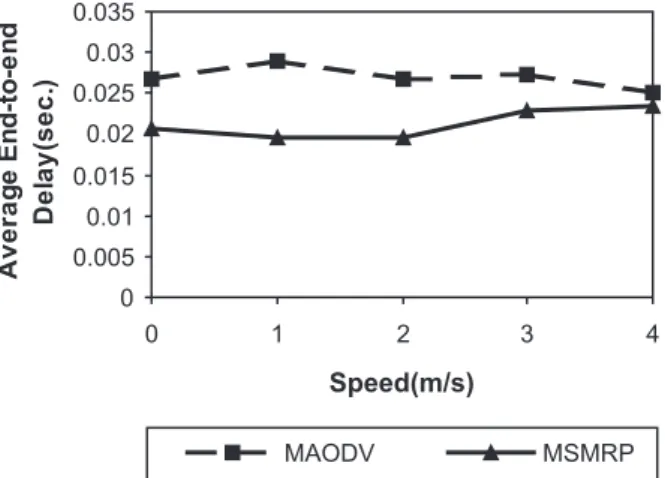
Fig. 6Average End-to-end Delay of Low Mobility
50-node Network. 0 0.005 0.01 0.015 0.02 0.025 0.03 0.035
0 1 2 3 4
Speed(m/s) A v e ra g e E n d -to -e n d Del a y( sec. ) MAODV MSMRP
Fig. 7Average End-to-end Delay of Low Mobility
There are seven group members in one multicast session. Figure 5 gives the result for 100 node network and the group members are distributed around the region edges. Figure 5(a)shows the
end-to-end delay between two leaf nodes. As expected, when a source node far away from the group leader sends data, MSMRP gives a notable low delay, especially when the network is static or moves very slowly. Figure 5(b)
shows the packet delivery ratio. The variation in packet delivery ratio becomes more signifi-cant once the nodes begin to move fast for both MSMRP and MAODV. The result shows that an increase in speed yields a decrease in the packet delivery ratio. This is due to the reason that the shared tree encounters more link breaks and re-pairs as nodes move faster. The frequent change of network topology often results in multiple at-tempts per repair to re-establish the shared-tree link connections. During the repair, some of the group members thus may not receive data pack-ets. We also noticed that MSMRP here has at least the same packet delivery ratio as MAODV. Figure 6 shows the end-to-end delay between two leaf nodes for a 50 node network. The re-sult indicates that MSMRP yet gives a notable lower delay than MAODV. Figure 7 illustrates the end-to-end delay between two leaf nodes for a 25 node network. The result indicates that MSMRP still gives lower delay than MAODV but the difference is not too notable.
The above three sets of experiments indicate that in static or low mobility network, the end-to-end delay of MSMRP is lower than that of MAODV, as expected. For small network, the difference of the end-to-end delay is not notable. For medium and large network, the difference is significant between MSMRP and MAODV.
0 1000 2000 3000 4000 5000 6000
0 5 10
Speed(m/s)
R
R
E
Q
N
um
be
rs
MAODV MSMRP
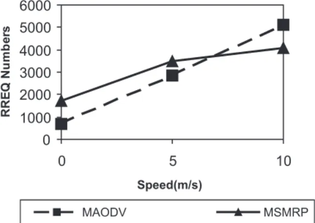
Fig. 8RREQ Numbers of 100-node Network.
Hence from the point of view of end-to-end de-lay, MSMRP outperforms MAODV in medium and large network. For small network, MAODV has comparable performance with MSMRP in end-to-end delay.
We next investigate route discovery overhead via the number of route discovery control pack-ets. To investigate our spatial locality observa-tion, we select a 100 node network in which the multicast group members are first distributed at the top left corner, as shown in Figure 4(b).
Three source nodes are used in the multicast group: group leader node, node close to the group leader, and a leaf node. Each source node sends five CBR data packets to the mul-ticast group. In Figure 8, we show the num-ber of RREQ control packets versus the change of node speed. As expected, in low mobility model, MSMRP has more RREQ routing pack-ets than MAODV. However, the difference is not significant. As nodes move more quickly, the numbers of RREQ routing packets for both pro-tocols are close to one another and the RREQ numbers increase abruptly as well. This is due to the fact that the frequent change of net-work topology causes more link repairs and hence more RREQ repair packets for shared-tree methods MSMRP and MAODV.
Performance of MSMRPx:
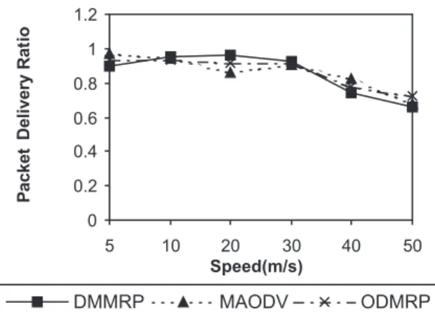
0 0.2 0.4 0.6 0.8 1 1.2
5 10 20 30 40 50
Speed(m/s) P acket D el iver y R at io
DMMRP MAODV ODMRP
Fig. 9. a)Packet Delivery Ratio of High Mobility
Sparse 100-node Network.
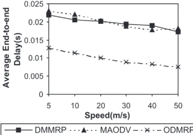
0 0.01 0.02 0.03 0.04 0.05
5 10 20 30 40 50
Speed(m/s)
DMMRP MAODV ODMRP
Averag e En d -to -e n d D el ay( s )
Fig. 9. b)Average End-to-end Delay of High Mobility
Sparse 100-node Network.
uses periodic RREQ and the modified MAODV also uses periodic RREQ, it is logical to as-sume that both will offer more or less identical packet delivery ratio and our simulation result, as stated in this section, supports that fact. In this simulation, by MAODV we mean the mod-ified MAODV.
To further explore the performance of shared-tree protocols in a high mobility network, we consider our MSMRPx and the modified MAODV. In addition, we also show perfor-mance comparison with the mesh-based mul-ticast routing scheme, ODMRP. We have con-ducted experiments for both sparse network and dense network. Maximum speeds are selected from 5meters/sec to 50 meters/sec to simulate
high mobility.
The first set of experiments is for a 100-node network. In the sparse mode, there are six members. In the dense mode, there are twenty-two members and eight source nodes. Figure
0 0.2 0.4 0.6 0.8 1 1.2
5 10 20 30 40 50
Speed (m/s) P acket D e liv e ry Rat io
DMMRP MAODV ODMRP
Fig. 10. a)Packet Delivery Ratio of High Mobility
Dense 100-node Network.
0.015 0.02 0.025 0.03 0.035
5 10 20 30 40 50
Speed (m/s)
DMMRP MAODV ODMRP
Averag e E n d -to -e n d D el ay( s )
Fig. 10. b)Average End-to-end Delay of High Mobility
Dense 100-node Network.
9(a)shows the packet delivery ratio and Figure
9(b)shows the end-to-end delay for the sparse
mode. Figure 10(a)shows the packet delivery
ratio and Figure 10(b)shows the end-to-end
de-lay for dense mode. In Figures 9(b)and 10(b),
we observe that the average end-to-end delay of MSMRPx is lower than that of MAODV. Also, the average end-to-end delay of MSM-RPx is higher than that of ODMRP. It is because ODMRP selects the shortest path to deliver data packets while MSMRPx selects relatively short path originated from new source nodes to de-liver data packets. In Figures 9(a)and 10(a), as
0 0.005 0.01 0.015 0.02 0.025
5 10 20 30 40 50
Speed(m/s)
DMMRP MAODV ODMRP
Averag
e
E
nd-
to-e
n
d
D
el
ay(
s
)
Fig. 11. a)Average End-to-end Delay of High Mobility
Sparse 50-node Network.
0 0.2 0.4 0.6 0.8 1 1.2
5 10 20 30 40 50
Speed(m/s)
P
acket
Del
ivery
R
at
io
DMMRP MAODV ODMRP
Fig. 11. b)Packet Delivery Ratio of High Mobility
Sparse 50-node Network.
The second set of experiments is conducted on a 50-node network. Figure 11(a)shows the
end-to-end delay and Figure 11(b)shows the packet
delivery ratio. In the sparse mode, there are six members. In the dense mode, there are four-teen members and five source nodes. Figure 11(a)shows end-to-end delay and Figure 11(b)
shows the packet delivery ratio for the sparse mode. Figure 12(a)shows the end-to-end delay
and Figure 12(b)shows the packet delivery ratio
for the dense mode. In Figure 11(a)and Figure
12(a), we observe that the average end-to-end
delay of MSMRPx is lower than that of the modified MAODV in most cases. The average end-to-end delay of both shared tree protocols is higher than that of ODMRP. In Figures 11(b)
and 12(b), packet delivery ratio of MSMRPx is
lower than that of the modified MAODV. This experiment once more validates that MSMRPx outperforms MAODV in terms of average end-to-end delay and packet delivery ratio for high speed, medium size ad hoc network.
0 0.005 0.01 0.015 0.02 0.025 0.03
5 10 20 30 40 50
Speed(m/s)
Averag
e
E
n
d
-to
-e
n
d
D
el
ay(
s
)
DMMRP MAODV ODMRP
Fig. 12. a)Average End-to-end Delay of High Mobility
Dense 50-node Network.
0 0.2 0.4 0.6 0.8 1 1.2
5 10 20 30 40 50
Speed(m/s)
P
acket
D
el
ivery
R
at
io
DMMRP MAODV ODMRP
Fig. 12. b)Packet Delivery Ratio of High Mobility
Dense 50-node Network.
6. Conclusion
We have compared the performances of our posed MSMRP protocol and the MAODV pro-tocol. The simulation was developed and im-plemented in the QualNet library. We did two sets of experiments: low mobility set and high mobility set. The simulation results of the low mobility set demonstrate reduction of the av-erage end-to-end delay over MAODV. It also reveals that MSMRP can deliver data packets ef-fectively. The simulation results of the high mo-bility set further show that MSMRPx is also ef-fective in reducing the end-to-end delay and in-creasing the network throughput. The proposed MSMRP also scales well for both medium and large size networks. Future work will address on how to adjust the local ring search diameter under various network size environments.
7. Acknowledgement
The authors would like to thank the referees and the editor for their comments that have con-tributed to improve the quality of the paper.
References
1] A. BALLARDIE, Core-Based Trees (CBT version
2)Multicast Routing,IETF RFC 2189, September
1997.
2] T. PUSATERI, Distance Vector Multicast Routing
Protocol,IETF RFC 1075, August 2000.
3] J. MOY, Multicast Extensinos to OSPF,IETF RFC
1584, Mar. 1994.
4] S. DEERING, D. L. ESTRIN, D. FARINACCI, V. JACOB
-SON, C.-G. LIU,ANDL. WEI, The PIM
Architec-ture for Wide-Area Multicast Routing,IEEE/ACM
Transactions on Networking, vol. 4, no. 2, April
1996, pp. 153–162.
5] S.-J. LEE, M. GERLA AND C.-C. CHIANG,
On-Demand Multicast Routing Protocol, Proceedings of the IEEE Wireless Communications and
Net-working NetNet-working Conference, pp. 1298–1304,
September 1999.
6] J. J. GARCIA-LUNA-ACEVES, E. L. MADRUGA, The
Core-assisted Mesh Protocol, IEEE Journal
Se-lected Area Communication,(Special Issue on
Ad-Hoc Networks)17(8), 1999.
7] E. M. ROYER ANDC. E. PERKINS, Multicast
Op-eration of the Ad-hoc On-demand Distance Vector Routing Protocol,Proceedings of the 5th ACM/IEEE International Conference on Mobile Computing and
Networking (MobiCom), pp. 207–218, August 1999.
8] C. W. WU, Y. C. TAY, C.-K. TOH, Ad Hoc Multicast
Routing Protocol Utilizing Increasing Id-numbers
(AMRIS)Functional Specification, Internet draft,
IETF, August 1998.
9] E. BOMMAIAH, M. LUI, A. MCAULEY, R. TALPADE,
AMRoute: Ad Hoc Multicast Routing Protocol,
Internet draft, IETF, August 1998.
10] L. JI ANDM. S. CORSON, A Lightweight Adaptive
Multicast Algorithm,Proceedings of IEEE GLOBE-COM, pp. 1036–1042, December 1998.
11] C. PERKINS AND P. BHAGWAT, Highly Dynamic
Destination-Sequenced Distance-Vector Routing
(DSDV)for Mobile Coomputers,SIGCOMM ’94:
Computer Communications Review, 24(4), pp. 234–
244, October 1994.
12] J. BROCH, D. JOHNSON ANDD. A. MALTZ,The
Dy-namic Source Routing in Ad Hoc Wireless Networks,
in T. Imielinski, H. Korth(Eds), Mobile Computing,
Kluwer Academic Publishers, Dordrecht, 1996, pp. 153–181.
13] Z. LIU ANDB. GUPTA, A Sender-initiated
Group-shared Ad-hoc On-demand Multicast Routing Pro-tocol,Proceeding of PDPTA’02, June 2002.
14] Y. KO ANDN. H. VAIDYA, Location-aided Routing (LAR)in Mobile Ad Hoc Networks,Proceedings
of ACM/IEEE International Conference on Mobile
Computing and Networking (MobiCom), pp. 66–75,
November 1998.
15] QualNet Simulator Version 3.0 User’s Manual,
Scalable Network Technologies, Inc., Los Angeles, 2001.
16] I. S. DEPARTMENT, Wireless LAN Medium Access
Control(MAC)and Physical Layer(PHY)
Specifi-cations,IEEE Standard 802.11 – 1997, 1994.
Received:July, 2003
Revised:June, 2004
Revised:March, 2005
Accepted:March, 2005
Contact address:
Ziping Liu Computer Science Department Southeast Missouri State University Cape Girardeau, MO 63701 USA e-mail:[email protected]
Contact address:
ZIPINGLIUreceived B.S. and M.S. degrees in engineering from Hefei
University of Technology, China, in 1990 and 1993 respectively, and M.S. degree in computer science and Ph.D. degree in engineering sci-ence from Southern Illinois University at Carbondale, Illinois, USA, in 1999 and 2000 respectively. She is an assistant professor of computer science at Southeast Missouri State University, USA. Her research in-terest include wireless networks, especially QoS issues, modeling and performance evaluation of the mobile ad hoc network, design and anal-ysis of algorithms for distributed systems, finite element analanal-ysis and boundary elementanalysis. She was a software engineer at PCS Mo-torola from January to August 2001.