TECHNICAL UNIVERSITY OF CLUJ‐NAPOCA
ACTA TECHNICA NAPOCENSIS
Series: Applied Mathematics, Mechanics, and Engineering Vol. 58, Issue III, September, 2015
MECHANICAL FEATURES OF SYMTHETIC GLUE BONDING OF
METALS WITH CERAMIC GLASS
Gábor PINTYE, Gheorghe ACHIMAŞ, Gavril PATAI
Abstract: Adhesive bonding using synthetic materials has gained a wide field of use in the last decade, at bonding metal sheets or metal parts, non-metallic or combined, especially in light construction and precision mechanics, but also in vehicle manufacturing. Instead of metal layer or soldering alloy, a thin layer of adhesive is used, which after application tightens and takes external forces through the mechanical strength due to its mass cohesion and adhesion between the adhesive and the surfaces to be joined. Adhesive bonding is a process with broad application worldwide. In many cases it replaces the classic combination (welding, riveting) and allows bonding of materials with different structures, as in the case studied (metal with glass).According to the mechanical theory connection bonding between the bearing surface and adhesive (or any coating, paint) are made by adhesive infiltration into the pores, asperities (roughness) of the bearing surface. However, this theory can not be generalized because a strong glued joint can be made in the case of smooth material (for example: glass, semiconductor silicon plates). A relatively new scientific branch deals with theoretical basis of the soldering technique, surface engineering(surface engineering, surface science).
Keywords: surface engineering, roughness, bonding technology, mechanical connection, strength,
metal-glass bonding.
1. INTRODUCTION
In order to obtain a good adhesion it is necessary to study the basic material and the adhesive which connects to. [5]
Adhesive bonding is a process with wide application in technology. As a related field to welding, in standardization, there are interesting, especially, the requirements regarding preparation of surfaces to be merged, and attempts of adhesive bonded joints. Bonding forces (adhesion and cohesion) have an important role to get a correct joint and to meet requirements (tensile strength, shear strength and detachment, etc. . .).
There are four state standards in force in this field. First, STAS 10535-79, corrlated to ST CAER 138-81 and replaced SR ISO
15787:2008, sets the rules of representation and notes on drawing of bonded joints obtained. The other three refer to mechanical attempts of adhesive bonding joints and correlated with corespondent standards DIN:
• STAS 12310/1-85, which establishes the conditions for sample preparation and surface to be bonded and test tubes sampling of adhesive bonded joints, for shear tests, tensile, peel (peel) and wear;
• STAS 12310/2-85, which establishes technical requirements for execution of shear test specimens taken from adhesive bonded joints, of the overlapping sheets.
2. MATERIALS FOR TEST TUBES
Two types of metal can be used to make up test tubes:
• Stainless Steel Sheet - 304-2B ASTM, (X5CrNi18-10), numeric symbol 1.430[2]
Chemical composition: Cmax - 0,07%; Simax 1 %; Mnmax 2 %; Cr 17-19 %; Ni 8-11
%; Pmax 0,045 %; Smax 0,015 %.
Mechanical features (Fig.1.):Tensile breaking strength: Rm = 520Mpa; Flow strength, flow limit: Rp 0,2 = 205MPa.; Elongation: A = 40%.
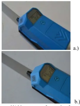
304-2B ASTM steel, (X5CrNi18-10), is the type of austenitic stainless chromium-nickel most used. Its most important property: ductility (elongation) and hard, cold workability and easy punching. The content of at least 7% Ni makes the structure to become fully austenitic, which provides "non-magnetic" properties and a very good weldability. It is widely used in manufacture of household appliances, pipelines and industrial tanks, industrial constructions. 2B (DIN 17441) - represents finished surface most often encountered to ensure corrosion resistance and evenness, having roughness of Ra= 0,10 - 0,30 µm and reflectivity max. 40 % (Fig.2. a and b).
Fig. 1. Stainless steel test tube - size 150x25x1 mm.
a.)
b.) Fig. 2. a and b) Measurement of uncovered surface
roughness.
• Metal sheet - DC 04 EK-M - EN 10209, numeric symbol1.0392 [2]
Chemical composition: Cmax - 0,08%; Mnmax - 0,5%; Pmax - 0,03%; Smax - 0,05%. Mechanical features (Fig.3.):
Tensile breaking strength: Rm = 270-350 MPa.
Flow strength, flow limit: Rp 0,2 = 220MPa. Elongation: A = 38 %.
DC 04 EK steel is type of steel which allows slight processing at deep drawing and offers a good wear at enamelling processes (wet or dry). DC 04 EK steel is widely used in the manufacture of household appliances, sanitary ware, architectural panels.
M - reprezintă laminare termomecanică (rulare), suprafaţa având rugozitate is thermomechanical lamination (rolling), with surface roughness of Ra = 0,60 - 1,90 µm (Fig.4. a and b).
After obtaining the metalic support, a protector paint layer is applied in electrostatic field.
Fig. 3. Steel test tube, painted in eletrostatic field - size 150x25x1 mm.
a.)
b.)
• Glass ceramic - is a polycrystalline material by controlled crystallizing of the basic glass.
Glass ceramic has an amorphous phase and one or more crystalline phases produced by a so-called "controlled crystallization" (Fig.5. a and b), in contrast to a spontaneous crystallization, which is usually is not desired in the glassmaking. Glass ceramic has the advantage of glass manufacturing, as well as the special properties of the ceramics.
All thermic properties of glass are important for the technology, due to the fact that during its production, the glass is heated, melted, cooled, thermally treated in a very wide range of temperatures (Fig.6.).
In this thermic treatment glass is crystallized, at base composition of glass "heterogeneous germs" are added - solid particles of other nature, in general ceramics, these germs help and control the process of crystallization.
a.
b. Fig. 5. The process of crystallization
a. - Germination, b. – Germs growth and formation of structure.[3]
Mechanical features (Fig.7.): Tensile breaking strength (tear):
100 250 (1) Longitudinal elongation module (Young’s module):[8]
120 120.000 (2)
Density:
3 / (3)
Fig. 6. Stages for obtaining glass ceramic.[10]
Fig. 7. Glass ceramic, EUROKERA,size 150x25x4 mm.
• One component adhesive silicone S95 CO4 (Fig.8.):
Fig. 8. One component adhesive silicone S95 CO4.
This adhesive was conceived especially for bonding glass ceramic while ensuring elasticity and tightness. The adhesive silicone is in the form of paste having a stable viscosity.[11]
3. SURFACES CONDITION
Surface roughness is made up of microirregularities of actual surface that influence the contact of surfaces with adhesive for bonding.
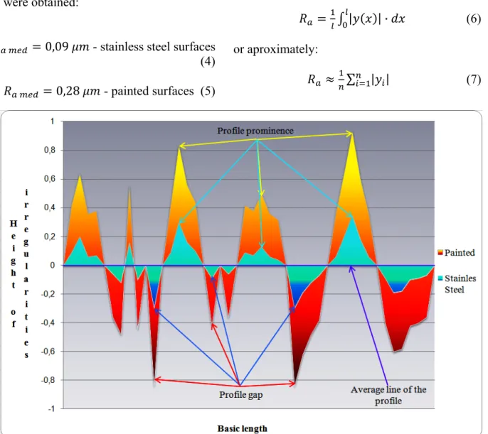
After surface measurement the following values were obtained:
0,09 - stainless steel surfaces
(4)
0,28 - painted surfaces (5)
Average arithmetic deviation of the profile,
- average arithmetic of absolute values of profile deviation, within limits of basis length (Fig.9.).
Average arithmetic deviation is calculated:
| | · (6)
or aproximately:
∑ | | (7)
Fig. 9. Theoretic representation of studied surfaces. - The projection profile is the profile
oriented to exterior material and hold between two consecutive intersections of profile with the average line.
- The gap of profile is that side facing the interior of the piece material and between two consecutive intersections of profile with average line.
- Basic length is the length of the reference line, which is used for the separation of irregularities that make up the surface roughness .[4]
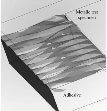
Fig. 10. Representation of average arithmetic deviation, reflecting the surface asperities. According to the mechanical theory
connection [1] the joint between the bearing surface and adhesive (or any coating, paint) is made by infiltration of the adhesive into the pores, asperities (roughness) of bearing surface (Fig.11.).
Fig. 11. Simulation of adhesive infiltration.
A relatively new scientific branch Surface Engineering deals with the theoretical basis of bonding technique, which is oriented towards modifying properties of the superficial parts to improve their functional performance. [6]
4. PREPARATION OF TEST TUBES
Test tubes are prepared in accordance with STAS standards 12310/1-85, SR EN 15434+A1:2010 (Annex D), SR EN 14869-1:2010 and DIN 53281 (Fig.12.).
Fig. 12. Test tube in compliance with SR EN 15434+A1:2010.
The research and studies conducted so far to joint bonding by overlapping were studied the Metalic test
specimen
same types (composite) of materials having the same thickness.
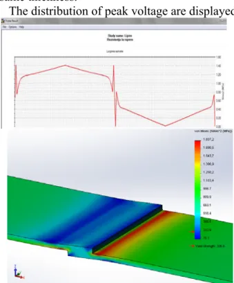
The distribution of peak voltage are displayed.
Fig. 13. Distribution of peak voltage at gluing by overlapping along the test tubes, using a thin layer of adhesive in the contact area by applying 100 N traction
force.
Fig. 14. Distribution of peak voltage at gluing by overlapping along the test tubes, using a coarse layer of adhesive in the contact area by applying 100 N traction
force.
Following the diagrams obtained (Fig.13. and Fig.14.) we can notice the influence of the
bending moment along the test tube. Moreover, we can see fixed areas (abutting ends and overlapped glued branch), a jump occuring near them.
Considering the studies conducted so far we investigate something new, using the overlapping joint bonding but with two different materials of different thicknesses
(metal +adhesive+ glass) (Fig.15.).
Fig. 15. Positioning and force infliction on studied test tubes.
Fig. 16. Distribution of peak voltage at gluing by overlapping along the metal test tubes, using a coarse layer of adhesive in the contact area by applying 100 N
traction force.
Due to the fact (Fig.16.). the glass ceramic
metal having a high bending near contact interface and decreasing towards the end of the test tube gives the impression of autocentering. To elliminate this tendency which has impact on the test tube (bending moment),we will use an addition of balancing to perform tensile tests (Fig.17. and Fig.18.).
Fig. 17. Calculation of addition for balancing.
Fig. 18. Calibrated test tubes.
5. TRACTION ATTEMPTS
Tensile tests for bonding assembly were performed in the laboratory of UTC-N, Faculty of Mechanical Engineering (Fig.19.).
Fig. 19. The machine for tensile testing: Zwick/Roell 150 kN.
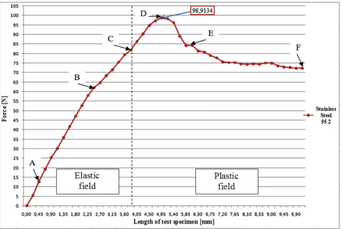
Fig. 20. Tensile curves obtained from stainless steel test tubes.
Fig. 22. Stages of test tubes deviation process at traction tests. Point corresponds to the initial situation,
where there are no tensions or deformations in the test tube. 0
In the first portion of the curve, the two sizes grow simultaneously, but the rate of growth is higher. In addition, the dependence of the two sizes is linear to the point corresponding to the limit of proportionality (Fig.22.).
Point ordinate, to which the material acts perfectly elastic, after unload (force removal) the test tube regains its original length, it is called elastic limit . (Fig.23.).
Starting from the point, the curve will tend to continue in a direction parallel to the x-axis, because deformation increases without force growing substantially (it is said that the material ,,flows”). This area marks the entrance to the plastic deformation of the material and proper tensile point is called flow limit.
Then an increase point of curve follows, without proportionality between the two sisez, which end in the maxim point, considered to be
tear limit or tensile strength of the material tested.
Near the point, that is the maximum amount of force, it is found that in a certain portion of test tube its cross-section decreases, the bottleneck point, a phenomenon that sharpens then until breaking point. The applied force decreases, leading to a descending path of the curve.[9]
Fig. 23. Representation of difference between elasticity and plasticity.
Table 1. Experimental results from the tensile test, stainless steel test tubes + adhesive + glass
Test
1 2 3 4 5 Exp Test tube n 1 2 3 4 5 Follow traction were hi test tub surface to cohes test tub degreas results w Fig Analy followin found in due to bond st the diffe Fig. 93.7 98.9 102 54.9 98.7 perimental t no. 112 141 137 141 136 wing tensi , the value igher and c es, therefor
(painted i ) ensures a sive forces. bes (
ed and cle were obtain
g. 24. Test tube yzing the ng tensile te n contact i low roughn trength (coh erent values
. 25. Test tube 79 91 .22 93 72 results from .53 .80 .08 .99 .82 ile testing es obtained
loser to on re we can in electros a better link
In the case ), aned of im ned with low
es of stainless tensile tests stainless ests (Fig.24 interfaces o ness not pr hesion) suf s obtained.
es of painted m tests. 4.5 5.2 10 7.5 5.5
m the tensile
5.2 4.9 5.2 5.1 5 carried (Table 1 ne another a
say that a static field, k and unifo e of stainles
which wer mpurities, di
wer values.
s steel materia s.
steel tests .), fracture on the meta roviding su fficient, ref material after 90 104 200 150 110
e test, painte
104 98 104 102 100 out at and 2) at dyed treated rm due ss steel re only ifferent al after tubes es were al side, fficient flecting tensile t f m s 6 j d p d i m r h t a a e d t b [ 8.022 8.191 9.003 4.798 8.424
ed test tubes
9.954 11.779 11.562 11.463 11.223 Analyzing test traction found due made of s strength nea 6. CONCLU During re oint bondin decisive ro properties w To obtain degreasing impurities is
Surface microirregu relatively sm have an imp
The highe the stronger adhesive de
Near the c a minimum even distrib distribution thickness o bending mo 7. BIBLIO [1].Balázs, Könyvki 9.3 9.8 10.2 5.4 9.8
s + adhesiv
11.2 9 14.1 2 13.7 3 14.1 3 13.6
g the paint n (Fig.25.),
to higher steel, ensu ar contact in
USIONS
search cond ng, importa ole, influe were discove n a suffici and cleani s not suffici roughness ularities, th
mall in rel portant role er the surfac
r the cohes eper into th contact inter m gap of a
bution of of worklo of the adhe oment as in t
OGRAFIE
Gy. . Rag adó. Budap
79 0
91 0
222 0
93 0
72 0
e + glass
253 0 180 0 708 0 199 0 682 0
ed tests tu cohesion f roughness uring a su
nterfaces.
ducted at th ant factors encing the ered (breaki iently stron ing contact ient. is made hese irreg ation to th
to achieve ce roughnes sive force p he bonding m
rface is nec adhesive th the worklo oad is influ
esive gap the cases pr
gasztástechn pest . 1982.
0.2913 0.2702 0.0986 0.1024 0.2116 Table 2. 0.2737 0.2837 0.2758 0.2705 0.2881 ubes follow fractures w of test tub ufficient bo
he overlapp which have e mechani
ing). ng glue jo
t interface
up of gularities heir depth, b
a strong bon ss or asperit penetrating
material. cessary to ha
at ensures oad. Unifo uenced by changing resented.
[2]. Cândea, V., Clasificarea și simbolizarea aliajelor feroase și neferoase. Editura U.T.PRESS. Cluj-Napoca. 2010.
[3]. Cândea, V.Atlas, structuri metalografice. Editura U.T.PRESS. Cluj-Napoca. 2012. [4]. Itu, T. Toleranțe și ajustaje în ingineria
mecanică. U.T.PRESS. Cluj-Napoca.2008. [5].Romand, M. .Surface Science and
Adhesion.Tempus Short Course Programme, TUB. Budapest .1996.
[6].Vermeșan, G. .Introducerea în Ingineria Suprafețelor, Editura Dacia, Cluj-Napoca. 1999.
[7].*** Stadiul si tendințele standardizării în domeniul sudării și al procedeelor conexe. Vol. 9: Lipirea metalelor cu aliaje și cu adezivi. București. 1990.
[8].***http://ceramics.org/wpcontent/uploads/2 010/09/bulletin_oct-nov2010.pdf
[9].***http://webspace.ulbsibiu.ro/adrian.pascu/ Curs_RM-1.pdf
[10].***http://www.eurokera.com/manufacturin g/
[11].*** http://www.otto-chemie.de/otto/full-
text-search/,_psmand,2.html?cat=Volltextsuche&q =Novasil%C2%AE+S+95
[12].***Solid Works 2013.
CARACTERISTICI MECANICE ALE ÎMBINĂRII PRIN LIPIRE CU ADEZIV SINTETIC A
METALELOR CU STICLĂ-CERAMICĂ
Rezumat: Lipirea cu adeziv pe bază de materiale sintetice a câştigat în ultimul deceniu un câmp larg de utilizare, la îmbinarea tablelor sau pieselor metalice, nemetalice sau combinate, îndeosebi în construcţia uşoară şi mecanică fină, dar şi în construcţia de maşini. În locul stratului de metal sau aliaj de lipit, intervine un strat subţire de adeziv care, după aplicare, se întăreşte şi preia forţele exterioare prin rezistenţa mecanică datorită coeziunii din masa lui, cât şi prin adeziunea dintre adeziv şi suprafeţele de îmbinat. Lipirea cu adezivi reprezintă un procedeu cu aplicare largă pe plan mondial. În foarte multe cazuri înlocuieşte îmbinarea clasică (sudarea, nituirea) şi permite îmbinarea materialelor cu structuri diferite, ca şi în cazul studiat (metal cu sticlă). Conform teoriei legăturii mecanice îmbinarea dintre suprafaţa portantăşi adeziv (sau orice acoperire, vopsea) se realizează prin infiltrarea adezivului în porii, asperităţile (rugozitatea) suprafeţei portante. Însă această teorie nu poate fi generalizată, pentru că se poate realiza o îmbinare lipită puternicăşi în cazul materialelor cu suprafaţă netedă (de exemplu: sticlă, plăcuţe semiconductoare de siliciu). Cu bazele teoretice a tehnicii de lipire se ocupă o ramurăştinţifică relativ nouă, ingineria suprafeţelor (surface engineering, surface science).
Gábor PINTYE, Phd. Student Eng., Technical University of Cluj-Napoca, Department of Manufacturing Engineering, Muncii Boulevard 103-105, Cluj-Napoca, ROMANIA, e-mail: [email protected];Satu-Mare 440187, Str. Careiului no.28/93, Judeţ Satu-Mare, 0770469564.
Gheorghe ACHIMAŞ, Prof. Dr. Eng., Technical University of Cluj-Napoca, Department of Manufacturing Engineering, Muncii Boulevard 103-105, Cluj-Napoca, ROMANIA, e-mail: [email protected]; Cluj-Napoca 400537, Str. Clăbucet no. 1/38, Judeţ Cluj, 0720 054863.