Potential Impact of Computational Techniques to Express the Solid
Dynamics in (Gas-Liquid-Solid) Multiphase Reactors
Saadat Ullah Khan Suri
Chemical Engineering, Balochistan University of Information Technology, Engineering and
Management Sciences, Quetta, Pakistan
[email protected] and [email protected]
Abstract
The computational fluid dynamics codes play a paramount role by demonstrating the system dynamics. The solid dynamics in a multiphase reactor can be analysed from (Chaos, Fractures, Clustering Discrete Element and Eulerian-Langrangian) simulation methods. The Chaos analysis is studied from pressure variation and time series. It includes the characterization of the flow region and their transition. The correlation dimension from the gas phase will describe the scale behaviour in the Chaos analysis. An effective flow model with definite investigation is obtained from this analysis. The flow regimes will be characterized by the structures variation. The volume of fluid and continuum surface force models elaborate on the fluidized bed bubble dynamics in the reactor. The bubbles formation and gasification process of (Fuel gas) are studied from parameters by including (Minimum fluidization velocity, Gas surface tension, Gas viscosity and Density). The results demonstrate the parameters which are influenced by (Particle density and Size). The investigation in time series signals for the biomass gasification process will be demonstrated from the fluidized bed hydrodynamics and system basics. The solid dynamics has been investigated by indicating a novel bubbling in biomass (Wood) in the gasification process time signals. The indication of complex signals in solid dynamics can be obtained from it simultaneously.
Key words:
Chaos Analysis, Volume of Fluid Method, Discrete Element Method and Eulerian- Eulerian Simulation
.
Introduction
The multiphase reactors are found in large industrial applications by including petrochemical, refinery, pharmaceutics, food and chemicals industries. The multiphase reactors are known for their characteristics of mass transfer in reactions zone. Thus, it keeps a paramount importance to design the solids flow region for an optimum process which can carry it effectively. There is combination of combination of different numerical methods from the solids flow region in a reactor can be identified. The various hydrodynamic properties can identify the solids flow region [1-13] . Chaos Analysis has a potential method to demonstrate the hydrodynamic properties in a multiphase reactor system. In this analysis, the flow region is identified from chaos invariants. The transitory region is characterized when an abrupt chaotic invariant is seen. These chaos invariants possess different kinds of features with a definite operating range value. The pressure variation with a time series is obtained from multiphase reactors as its chaos signal [14-25]. The other transfer properties by including solid phase hold-up can be measured in (Gas-Liquid-Solid) fluidized bed reactor. The solids flow region is uniform under liquid and gas as the feed. The self-arranged clustering property in (Gas-Liquid-Solid) fluidized bed reactor is a dynamic process that includes the rapid propagation of the gas bubbles [26-32].
The image processing technique has a paramount importance to evaluate the process by showing space-time values clearly. A metal-oxide-semiconductor is used there to show the particles and bubbles. It shows the effect of (Liquid, Solid particle characteristics and Operating conditions) on self-arranged process structure in (Gas-Liquid-Solid) fluidized bed reactor. The solid particle dynamics or behavior in this
reactor being studied from the fractal analysis. The structure of these bubbles is studied from the fractal method. These solids dynamics are dependent on eddies formation inflow and their chaotic behavior is linearly studied from these particles and bubbles from time sequence data in fractal analysis with different frequencies. The variation of pressure in this reactor is analyzed from different process conditions in Hurtz’s range. The time series of pressure variation is demonstrated from Brownian motion. The turbulence value in solid particles can be demonstrated from it in the (Gas-Liquid-Solid) fluidized bed reactor. These correlated values are strongly influenced from their respective phases flow region. The determination of the phase’s pressure and conductivity values give a rise to evaluate the flow structure by flow area transition [33-36].
The numerical methods by including (Eulerian-Eulerian and Eulerian-Lagrangian) are used to evaluate the complex solid dynamics in the multiphase reactors. The solid dynamics for biomass gasification in the bubbling region of the fluidized bed is evaluated from these models. The gasification process is modeled from steady-state (Eulerian-Eulerian) simulation code. A homogenous reaction takes place with nitrogen gas phase in this process. The solid dynamics in porous media of the fluidized bed reactor is being simulated from the Langrangian simulation method [31, 43-51].
Literature Review:
Chaos behavior in Multiphase reactor system:
Mingyan and Zhong [52] did the research work on chaos behaviors in a bubble column reactor. The chaos characteristic of this system is solely based on the determination of time series in a sequence of pressure variation in a reactor. The demonstration of the flow region and its transition is being made possible in phases (Liquid and Gas). When there is a heterogeneous flow region is exists, a superficial gas velocity can determine whether the single phase is dominant in this reactor system. The formation of an optimum flow model is being met through chaos analysis. The flow region and its transition can be demonstrated from the structural change.
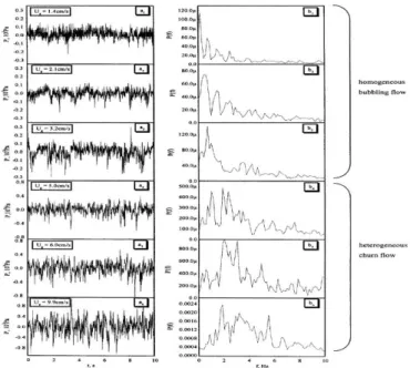
Figure.1: Illustration of pressure change with time series analysis [52].
Figure 1 shows the pressure variation and power patterns with time series analysis at different superficial gas velocities. There is an observation that low-frequency effects on the power spectrum are due to bubbling flow regions. The lower frequency is due to the flow region change which is demonstrated in Fig.1 (b2 and b3). There are observed
high-frequency peaks in transition range at high value of superficial gas velocity from 9.9 cm/s to 5 cm/s. The frequency profile tends to decrease on low superficial gas velocities from 3.2
cm/sec to 1.4 cm/sec. Thus, a frequency profile varies with superficial gas velocities.
Figure. 2: Illustration of chaos invariants with correlated radius at different regions in a Bubble column reactor [52].
Figure 2 shows the log plot of correlated integral and radius of the sphere with a variation in superficial gas velocities. It is being demonstrated in figure 2 that the flow region is being visible from the structure curves. The linear section is shown from the correlated curves in figures 2 (a,b,c). A wave appeares in the section when there comes a transition in the flow region. It is due to the lower frequency in power spectrum. This slope gets saturated at one value with an increase in superficial gas velocity. The correlation dimension demonstrates that structure distribution in homogenous bubbling flow regions is due to density. It shows the flow property of the phase in a homogeneous bubbling flow region. When there is transition in a phase from homogenous bubbling flow to heterogeneous flow region, there appear linear slopes which are demonstrated in figure 2 part (d,e,f,). In this work, there are three linear (Scale 1, Scale 2 and Scale 3) sections. It is helpful to get the correlation dimension from variable superficial gas velocities. There is no phase space in the structure due to the uneven distribution of the bubbles at the heterogeneous flow region [53, 54].
Hence, these chaos analyses demonstrate the solid dynamics with variations in pressure and time. It arises to show the difference between (Homogeneous and Churn) flow regions in a multiphase bubble column reactor. These analyses describe an understanding of flow region transition by demonstrating solid dynamics [55].
Analysis on Fractual Structure in Multiphase reactor:
Figure. 3: Illustration of amplified pictures of (Gas-Liquid- Solid) riser [56].
Figure 3 shows the amplified pictures on (Gas-Liquid and Solid) flow images at three phase’s riser. The fractal body is a part of these phases. The similarities between the phases are demonstrated from the amplified pictures. It is being enlarged to show (Gas-Liquid-Solid) flows pattern in the multiphase reactor. It shows that the fractal dimensions are in non-linear flow structures. There does not exist absolute similarity in (Gas-Liquid-Solid) riser. In (Gas-Liquid-Solid) riser, the operating conditions are; (AB-8 resin of diameter =0.6mm, Superficial velocity Um = 5.56 mm/s and Mass flow rate of
solid Gs = 80.66 kg/(m2·h)).
Figure.4: Illustration of primary liquid flow at variable superficial liquid velocities [56].
Figure 4 shows original (Gas-Liquid-Solid) patterns at variable superficial liquid velocities. The figure 4(a), at 5.56mm/s of liquid superficial velocity and GSa= 74.27
kg/(m2·h), the dilution is minimum. It tends to increase in Fig. 4 (b,c,d) with superficial velocities and solid flow from um = (6.67, 7.78 and 8.89) mm/s at Gs (72.97, 73.81 and 68.57 ) kg/(m2·h) simultaneously. It is being demonstrated that at
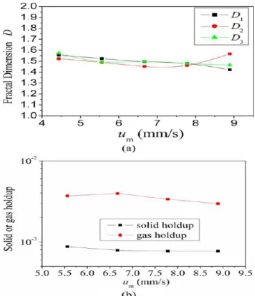
high superficial liquid velocity, the flow becomes dilute with a gas bubble and solid particles. Figure 5 shows the fractal dimension of all three phases by including (Gas, Liquid and Solid). The nature of fracture at three phase’s flows is demonstrated from gas bubbles on different superficial gas velocities. There is a decrease in fractal values (D1 and D3)
with an increase in superficial gas velocity demonstrated in figure 5 (a). There is also shown the effect of gas or solids holdup with change in superficial gas velocity in figure 5(b). It is clearly shown that a decrease in gas and solids hold-up with an increase in superficial gas velocity.
Figure. 5: Illustration of fractal dimension, gas and solid hold with variation in superficial velocities [56].
Figure.6: Illustration of bubble separation to evaluate three phase’s hold-up [56].
The bubbles are separated from the separation treatment. It includes the ejection of bubbles. Every gas-liquid-solid image can be recognized by using this technique. The two images (liquid and solid bubble image) are obtained in figure 6 (b,c) by using a high image capturing technique. The factors (Volume, Solid-holdup and Velocity) can be calculated from bubble pattern image.
Thus, fractal analysis shows the solid particles motion in different phases flow from (High image resolution) processing. There is an effect on the solid and gas phase’s hold up with a variation in superficial gas and liquid velocities [57].
Simulation on Low Solid Holdup in Bubble Column Reactor:
dynamics were investigated from very lower solids particles hold up. The (Discrete particle and Volume of fluid) methods were performed to evaluate the bubbling dynamics in the reactor. The solid particle characteristics influence was studied from (Size, Numbers, and Density). There are other operating conditions on a liquid phase by including (Superficial velocity, Surface tension and Viscosity). The investigation also consists of the particle entrainment with an increase in velocity of three phases (Gas-Liquid-Solid) flows.
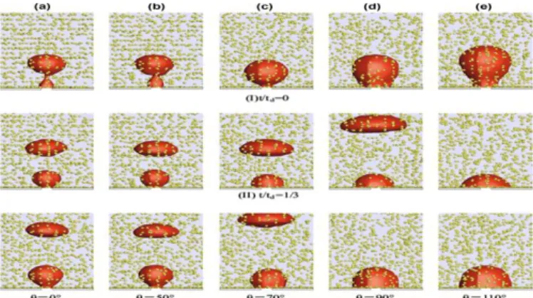
Figure.7:Illustration on gas bubble dynamics with a different angle on the gas nozzle on constant solid particle size [58].
Figure 7 shows the gas bubble dynamics for variation in the angle of the nozzle. There is an effect on nozzle wettability inflow. The contact angle changes from 0° to 110° degrees. These properties by including (Fluid and particles) are constant. When the contact angle values are between (0° to 50°) degrees, the gas bubbles are vertical with the inner edge in gas bubble formation. When the contact angle is higher than the 70° degree, the gas bubbles come to baseline by extending horizontally. Thus, an increase tendency of gas bubbles develops with detached gas bubble volume by increasing contact angle, as demonstrated in figure 7 (c,d,e) of the bubble column reactor.
Figure. 8: Illustration on particle entrainment around the gas bubbles in a bubble column reactor [58].
Figure 8 shows the rise of gas bubbles with solids particle around it. The particle entrainment proves to be in a paramount role to describe the solid fluidization. The above figure 8 describes the numerical simulation of a rising bubble. The gas bubbles are of diameter 20mm with a spherical shape. The solids particles were at rest initially. After it, they are distributed randomly over the bottom area of the reactor. The main objective of the present research work is to compare the
solid dynamics simulation results with experimental ones. In this simulation study, the solid particles are dragged from gas bubbles; it describes an agreement between temporary variations of the solids particles with entrainment with the gas bubbles. The solid particles existed in the system follow towards the low velocity of the gas bubbles. This behavior from solid particle effect the fluidization process which completely gets agree with experimental results.
Henceforth, Solid particle s motion at constant volume is being analysed in a (Gas-Solid) multiphase reactor. There is an observation that gas bubbles acquire motion from solid particles contact [59].
Evaluation of Solid Dynamics from Biomass Gasification process
Oevermann, Gerber, and Behrendt [60] did the research work on (Euler-Langrangian) numerical model to simulate the wood gasification in a bubbling fluidized bed reactor. The exhaust gas phase is simulated through the Navier-Stokes equation.
On the other hand, the solid phase is simulated with (Discrete Element) method. This simulation describes the gas phase and zero-dimensional simulation of each solid particle in (Pyrolysis and Gasification) processes with heat and mass transfer.
The simulation results have a focus on wood-feeding rate for exhaust gas composition analysis. It also provides information on temperature influence on exhaust gas composition. The simulation is carried out under the data in figure 9.
Figure. 9: Illustration on Experimental data from the reactor (Temperature, Time and Height) [60].
After it, Carbon mono-oxide (CO) produces from gasification process with charcoal particles. These two reactions produce carbon mono-oxide (CO) directly at the fuel inlet.
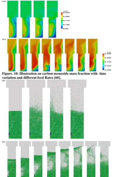
Figure. 10: Illustration on carbon monoxide mass fraction with time variation and different feed Rates [60].
Figure. 11:.Illustration on solid particles distribution in gas-solid fluidized bed reactor at constant time and different wood-feeding rates [60].
Figure 11 shows the solid particles distribution in the reactor for biomass (wood) gasification at different feeding rates. As the feeding rate is increased, the fluidization gets high. Figure 11 (a) describes the fluidization process at a biomass feeding rate of (0.105) kg/h. At his rate, the solid bed is fluidized and seldom bubbles are formed in a reactor. While at a biomass feed rate of (0.21) kg/hr, the solid bed comes into bubbling fluidization state. There is a violent eruption of bubbles as shown in figure 11(b) at (0.21) kg/hr of biomass feeding rate. This qualitative behavior leads towards an increase in amplitude and frequencies of solid bed.
Hence, the solid particles of biomass (Wood) particles show their process operability by regarding in production of carbon mono-oxide under different reaction stages. The primary analyses for the time series data are to plot the data from the measured signals. It shows the time scale and nature of the flow. The mass and momentum transfer equations numerical
investigations are required for characterization of gaseous interfaces in the reactor for two (Gas and Solid) fluidization. The solid particle distribution demonstrates the degree of fluidization which leads towards the production of fuel at different biomass (Wood) feeding rates [61-65].
Conclusions:
1. These transitional analyses are able to characterize the flow region transition in the (Gas-Liquid-Solid) multiphase reactor. It provides the data set on structure change evaluation. The integral correlation demonstrates the nature of the flow region and the multiplicity of the linear section. The solid dynamics evaluation comes from these multi-scale behaviors from an appropriate multi-flow characterization. Thus, It is an unprecedented result declaration for the identification of the phase’s flow regions and their transition.
2. The fractal analysis evaluates the solid dynamics with the degree of agglomeration in the (Gas-Liquid-Solid) multiphase reactor. Their phase’s holdup affects fractal analysis. There is an observation from the results that the fractal dimension increase with phase’s holdup. The solid aggregation can be reduced from high superficial liquid phase velocity. These results can guide the design of the (Gas-Liquid-Solid) reactor.
3. The solid clustering demonstrates the distribution is not uniform in the (Gas-Liquid-Solid) multiphase reactor. There exist multiplex clusters in (Gas-Liquid-Solid) riser. They arise from five main factors by including (Operating conditions, Liquid and Particles properties). These results are capable of demonstrating the fundamental understanding for evaluation of three phases (Gas-Liquid-Solid) fluidization for high efficiency.
4. The (Volume of fluid) model from computational fluid dynamics shows its viability by simulating the effect of solid particle dynamics in a multiphase reactor. The results are in agreement with experimental ones. The solid particle’s movement has a focus on gas bubbles diameter and its velocity in multi phase’s flows. The increase in contact angle makes large gas bubbles. The high-gas phase velocity tends to lower the surface tension force. This force increases the superficial liquid phase velocity and viscosity.
6. The limitations of computational fluid dynamics include that models do not measure accurate phenomenon with high precision. A large simulation coupling can create difficulty in access. There is needed a specific permission and expense to use it. There can accumulate error with unknown sources and experiments cannot validate without eliminating them.
Acknowledgments
The author is very much thankful to the staff of Balochistan University of Information Technology, Engineering and Management Sciences Quetta for their continuous support during the research.
References
1. M. F. Abid, S. M. Ahmed, H. H. Hasan, D. Al-Mously, and S. Barghi, "Hydrodynamic Study of an Ebullated-bed Reactor in the H-oil Process," Iranian Journal of Science and Technology, Transactions A: Science, vol. 43, no. 3, pp. 829-838, 2019.
2. N. Yang, J. Chen, H. Zhao, W. Ge, and J. Li, "Explorations on the multi-scale flow structure and stability condition in bubble columns," Chemical Engineering Science, vol. 62, no. 24, pp. 6978-6991, 2007.
3. R. Panneerselvam, S. Savithri, and G. Surender, "CFD simulation of hydrodynamics of gas–liquid–solid fluidised bed reactor," Chemical Engineering Science,
vol. 64, no. 6, pp. 1119-1135, 2009.
4. Y. Li, J. Zhang, and L.-S. Fan, "Numerical simulation of gas–liquid–solid fluidization systems using a combined CFD-VOF-DPM method: bubble wake behavior,"
Chemical Engineering Science, vol. 54, no. 21, pp. 5101-5107, 1999.
5. G. C. Glover and S. C. Generalis, "Gas–liquid–solid flow modelling in a bubble column," Chemical Engineering and Processing: Process Intensification,
vol. 43, no. 2, pp. 117-126, 2004.
6. M. van Sint Annaland, N. Deen, and J. Kuipers, "Numerical simulation of gas bubbles behaviour using a three-dimensional volume of fluid method," Chemical engineering science, vol. 60, no. 11, pp. 2999-3011, 2005.
7. M. van Sint Annaland, N. Deen, and J. Kuipers,
"Numerical simulation of gas–liquid–solid flows using a combined front tracking and discrete particle method,"
Chemical engineering science, vol. 60, no. 22, pp. 6188-6198, 2005.
8. G. Yang, B. Du, and L. Fan, "Bubble formation and dynamics in gas–liquid–solid fluidization—A review,"
Chemical engineering science, vol. 62, no. 1-2, pp. 2-27, 2007.
9. M. P. Duduković, F. Larachi, and P. L. Mills,
"Multiphase catalytic reactors: a perspective on current knowledge and future trends," Catalysis reviews, vol. 44, no. 1, pp. 123-246, 2002.
10. G. Liu, X. Zhang, L. Wang, S. Zhang, and Z. Mi, "Unsteady-state operation of trickle-bed reactor for
dicyclopentadiene hydrogenation," Chemical Engineering Science, vol. 63, no. 20, pp. 4991-5002, 2008.
11. D. Janecki, A. Burghardt, and G. Bartelmus, "Influence of the porosity profile and sets of Ergun constants on the main hydrodynamic parameters in the trickle-bed reactors," Chemical Engineering Journal, vol. 237, pp. 176-188, 2014.
12. R. Chowdhury, E. Pedernera, and R. Reimert, "Trickle‐ bed reactor model for desulfurization and
dearomatization of diesel," AIChE journal, vol. 48, no. 1, pp. 126-135, 2002.
13. V. Tukač et al., "The behavior of pilot trickle-bed reactor under periodic operation," Chemical engineering science, vol. 62, no. 18-20, pp. 4891-4895, 2007. 14. J. Liu, M. Liu, and H. Zongding, "Clustering behaviour
in gas–liquid–solid circulating fluidized beds with low solid holdups of resin particles," The Canadian Journal of Chemical Engineering, vol. 88, no. 4, pp. 586-600, 2010.
15. X. Jia, X. Wang, J. Wen, W. Feng, and Y. Jiang, "CFD modelling of phenol biodegradation by immobilized Candida tropicalis in a gas–liquid–solid three-phase bubble column," Chemical engineering journal, vol. 157, no. 2-3, pp. 451-465, 2010.
16. M. Schubert, T. Bauer, and R. Lange, "Instationäre Betriebsweise zur Leistungssteigerung technischer Rieselbettreaktoren," Chemie Ingenieur Technik, vol. 78, no. 8, pp. 1023-1032, 2006.
17. J. Silva, F. Lima, C. Abreu, and A. Knoechelmann, "Experimental analysis and evaluation of the mass transfer process in a trickle-bed reactor," Brazilian Journal of Chemical Engineering, vol. 20, no. 4, pp. 375-390, 2003.
18. K. Lappalainen, M. Manninen, and V. Alopaeus, "CFD modeling of radial spreading of flow in trickle-bed reactors due to mechanical and capillary dispersion,"
Chemical Engineering Science, vol. 64, no. 2, pp. 207-218, 2009.
19. J. Silva, "Dynamic modelling for a trickle-bed reactor using the numerical inverse Laplace transform
technique," Procedia Engineering, vol. 42, pp. 454-470, 2012.
20. R. J. Lopes and R. M. Quinta-Ferreira, "Turbulence modelling of multiphase flow in high-pressure trickle-bed reactors," Chemical Engineering Science, vol. 64, no. 8, pp. 1806-1819, 2009.
21. I. Iliuta, S. Bildea, M. Iliuta, and F. Larachi, "Analysis of trickle bed and packed bubble column bioreactors for combined carbon oxidation and nitrification," Brazilian Journal of Chemical Engineering, vol. 19, no. 1, pp. 69-88, 2002.
22. M. Bazmi, S. Hashemabadi, and M. Bayat, "CFD simulation and experimental study of liquid flow mal-distribution through the randomly trickle bed reactors,"
23. A. Atta, S. Roy, and K. D. Nigam, "Investigation of liquid maldistribution in trickle-bed reactors using porous media concept in CFD," Chemical engineering science, vol. 62, no. 24, pp. 7033-7044, 2007.
24. E. Gorshkova, M. Manninen, V. Alopaeus, H. Laavi, and J. Koskinen, "Three-Phase CFD-Model for Trickle Bed Reactors," International Journal of Nonlinear Sciences and Numerical Simulation, vol. 13, no. 6, pp. 397-404, 2012.
25. A. Heidari and S. H. Hashemabadi, "CFD simulation of isothermal diesel oil hydrodesulfurization and
hydrodearomatization in trickle bed reactor," Journal of the Taiwan Institute of Chemical Engineers, vol. 45, no. 4, pp. 1389-1402, 2014.
26. D. Ma, M. Liu, Y. Zu, and C. Tang, "Two-dimensional volume of fluid simulation studies on single bubble formation and dynamics in bubble columns," Chemical Engineering Science, vol. 72, pp. 61-77, 2012.
27. Z. Yujie, L. Mingyan, X. Yonggui, and T. Can, "Three-dimensional volume of fluid simulations on bubble formation and dynamics in bubble columns," Chemical engineering science, vol. 73, pp. 55-78, 2012.
28. F. Mousazadeh, H. van den Akker, and R. Mudde, "Eulerian simulation of heat transfer in a trickle bed reactor with constant wall temperature," Chemical engineering journal, vol. 207, pp. 675-682, 2012. 29. L. M. de Matos Jorge, R. M. M. Jorge, and R. Giudici,
"Experimental and numerical investigation of dynamic heat transfer parameters in packed bed," Heat and mass transfer, vol. 46, no. 11-12, pp. 1355-1365, 2010. 30. A. T. Jarullah, I. M. Mujtaba, and A. S. Wood, "Kinetic
parameter estimation and simulation of trickle-bed reactor for hydrodesulfurization of crude oil," Chemical Engineering Science, vol. 66, no. 5, pp. 859-871, 2011. 31. A. Silva et al., "Fluid dynamics and reaction assessment
of diesel oil hydrotreating reactors via CFD," Fuel Processing Technology, vol. 166, pp. 17-29, 2017. 32. T. Tohidian, O. Dehghani, and M. Rahimpour,
"Modeling and simulation of an industrial three phase trickle bed reactor responsible for the hydrogenation of 1, 3-butadiene: A case study," Chemical Engineering Journal, vol. 275, pp. 391-404, 2015.
33. L.-S. Fan, G. Yang, D. Lee, K. Tsuchiya, and X. Luo, "Some aspects of high-pressure phenomena of bubbles in liquids and liquid–solid suspensions," Chemical engineering science, vol. 54, no. 21, pp. 4681-4709, 1999.
34. X. Wang, H. Dong, X. Zhang, L. Yu, S. Zhang, and Y. Xu, "Numerical simulation of single bubble motion in ionic liquids," Chemical engineering science, vol. 65, no. 22, pp. 6036-6047, 2010.
35. A. Sokolichin and G. Eigenberger, "Gas—liquid flow in bubble columns and loop reactors: Part I. Detailed modelling and numerical simulation," Chemical engineering science, vol. 49, no. 24, pp. 5735-5746, 1994.
36. A. Sokolichin, G. Eigenberger, A. Lapin, and A. Lübert, "Dynamic numerical simulation of gas-liquid two-phase
flows Euler/Euler versus Euler/Lagrange," Chemical engineering science, vol. 52, no. 4, pp. 611-626, 1997. 37. D. Pfleger, S. Gomes, N. Gilbert, and H.-G. Wagner,
"Hydrodynamic simulations of laboratory scale bubble columns fundamental studies of the Eulerian–Eulerian modelling approach," Chemical Engineering Science,
vol. 54, no. 21, pp. 5091-5099, 1999.
38. D. Pfleger and S. Becker, "Modelling and simulation of the dynamic flow behaviour in a bubble column,"
Chemical engineering science, vol. 56, no. 4, pp. 1737-1747, 2001.
39. D. Iranshahi, M. Jafari, R. Rafiei, M. Karimi, S. Amiri, and M. R. Rahimpour, "Optimal design of a radial-flow membrane reactor as a novel configuration for
continuous catalytic regenerative naphtha reforming process considering a detailed kinetic model,"
International journal of hydrogen energy, vol. 38, no. 20, pp. 8384-8399, 2013.
40. I. Elizalde, F. S. Mederos, M. del Carmen Monterrubio, N. Casillas, H. Díaz, and F. Trejo, "Mathematical modeling and simulation of an industrial adiabatic trickle-bed reactor for upgrading heavy crude oil by hydrotreatment process," Reaction Kinetics,
Mechanisms and Catalysis, vol. 126, no. 1, pp. 31-48, 2019.
41. W. Wu and Y.-L. Li, "Selective hydrogenation of methylacetylene and propadiene in an industrial process: a multiobjective optimization approach,"
Industrial & engineering chemistry research, vol. 50, no. 3, pp. 1453-1459, 2011.
42. A. T. Jarullah, I. M. Mujtaba, and A. S. Wood, "Kinetic model development and simulation of simultaneous hydrodenitrogenation and hydrodemetallization of crude oil in trickle bed reactor," Fuel, vol. 90, no. 6, pp. 2165-2181, 2011.
43. T. Li, X. Ku, and T. Løva, "CFD simulation of devolatilization of biomass with shrinkage effect,"
Energy Procedia, pp. 2-7, 2016.
44. J. T. Cornelissen, F. Taghipour, R. Escudié, N. Ellis, and J. R. Grace, "CFD modelling of a liquid–solid fluidized bed," Chemical Engineering Science, vol. 62, no. 22, pp. 6334-6348, 2007.
45. S. Brusca, F. Famoso, R. Lanzafame, S. Mauro, M. Messina, and S. Strano, "Pm10 dispersion modeling by means of cfd 3d and Eulerian–Lagrangian models: analysis and comparison with experiments," Energy Procedia, vol. 101, pp. 329-336, 2016.
46. X. Zhang and G. Ahmadi, "Eulerian–Lagrangian simulations of liquid–gas–solid flows in three-phase slurry reactors," Chemical Engineering Science, vol. 60, no. 18, pp. 5089-5104, 2005.
47. R. J. Lopes and R. M. Quinta-Ferreira, "CFD modelling of multiphase flow distribution in trickle beds,"
Chemical Engineering Journal, vol. 147, no. 2-3, pp. 342-355, 2009.
engineering science, vol. 59, no. 22-23, pp. 5403-5410, 2004.
49. S. Rabbani, T. Sahmim, and M. Sassi, "Numerical Modelling and Simulation of Gas-Liquid Trickle Flow in Trickle Bed Reactor Using an Improved
Phenomenological Model," Energy Procedia, vol. 105, pp. 4140-4145, 2017.
50. M. Da Silva, E. Schleicher, and U. Hampel,
"Capacitance wire-mesh sensor for fast measurement of phase fraction distributions," Measurement Science and Technology, vol. 18, no. 7, p. 2245, 2007.
51. M. Schubert, H. Kryk, and U. Hampel, "Slow-mode gas/liquid-induced periodic hydrodynamics in trickling packed beds derived from direct measurement of cross-sectional distributed local capacitances," Chemical Engineering and Processing: Process Intensification,
vol. 49, no. 10, pp. 1107-1121, 2010.
52. M.-Y. Liu, Z.-D. Hu, and J.-H. Li, "MULTI-SCALE CHARACTERISTICS OF CHAOS BEHAVIOR IN GAS-LIQUID BUBBLE COLUMNS," Chemical Engineering Communications, vol. 191, no. 8, pp. 1003-1016, 2004/08/01 2004.
53. J. Van der Schaaf, J. Van Ommen, F. Takens, J. Schouten, and C. Van den Bleek, "Similarity between chaos analysis and frequency analysis of pressure fluctuations in fluidized beds," Chemical Engineering Science, vol. 59, no. 8-9, pp. 1829-1840, 2004. 54. C. M. van Den Bleek, M.-O. Coppens, and J. C.
Schouten, "Application of chaos analysis to multiphase reactors," Chemical Engineering Science, vol. 57, no. 22-23, pp. 4763-4778, 2002.
55. M. Liu and Z. Hu, Nonlinear analysis and prediction of time series in multiphase reactors. Springer Science & Business Media, 2013.
56. J. Liu, M. Liu, and Z. Hu, "Fractal Structure in Gas– Liquid–Solid Circulating Fluidized Beds with Low Solid Holdups of Macroporous Resin Particles,"
Industrial & Engineering Chemistry Research, vol. 52, no. 33, pp. 11404-11413, 2013.
57. C. Bramsiepe et al., "Low-cost small scale processing technologies for production applications in various environments—Mass produced factories," Chemical
Engineering and Processing: Process Intensification,
vol. 51, pp. 32-52, 2012.
58. Y. Xu, M. Liu, and C. Tang, "Three-dimensional CFD– VOF–DPM simulations of effects of low-holdup particles on single-nozzle bubbling behavior in gas– liquid–solid systems," Chemical engineering journal,
vol. 222, pp. 292-306, 2013.
59. S. Razzak, J. Zhu, and S. Barghi, "Effects of Particle Shape, Density, and Size on a Distribution of Phase Holdups in a Gas− Liquid− Solid Circulating Fluidized Bed Riser," Industrial & engineering chemistry research, vol. 49, no. 15, pp. 6998-7007, 2010. 60. M. Oevermann, S. Gerber, and F. Behrendt, "Euler–
Lagrange/DEM simulation of wood gasification in a bubbling fluidized bed reactor," Particuology, vol. 7, no. 4, pp. 307-316, 2009.
61. S. Sharma and P. N. Sheth, "Air–steam biomass gasification: experiments, modeling and simulation,"
Energy conversion and management, vol. 110, pp. 307-318, 2016.
62. Y. Li, L. Yan, B. Yang, W. Gao, and M. R. Farahani, "Simulation of biomass gasification in a fluidized bed by artificial neural network (ANN)," Energy Sources, Part A: Recovery, Utilization, and Environmental Effects, vol. 40, no. 5, pp. 544-548, 2018.
63. D. Mess, A. F. Sarofim, and J. P. Longwell, "Product layer diffusion during the reaction of calcium oxide with carbon dioxide," Energy & Fuels, vol. 13, no. 5, pp. 999-1005, 1999.
64. B. Weber, M. von Campenhausen, T. Maßmann, A. Bednarz, and A. Jupke, "CFD based compartment-model for a multiphase loop-reactor," Chemical Engineering Science: X, vol. 2, p. 100010, 2019/05/01/ 2019.