NEW
2005
CATALOG
Robotic Collision Sensor and
Axial Compliance Device
Protector
™Product Description
The Protector™is a collision sensor, or crash protection device, designed to prevent costly damage to robotic end-effectors resulting from robot crashes. Its robust design also allows the unit to be used as an axial compliance device for end-effectors. In response to many customer requests, the Protector’s features include: automatic reset, high repeatability, large moment and torsional rotation, rugged design and low cost. The Protector’s capabilities and features make it a worthwhile investment to pro-tect robots and tooling while minimizing downtime and eliminating the need for human intervention.
Product Advantages
High Repeatability: Following a collision, the use of
precise locating components enables the Protector to reset to within 0.001 inches of its original position.
Generous Range of Motion: During a crash the
Protector can comply large distances in response to any type of crash (angular, axial or torsional) thus allowing the robot controller ample time to take corrective action.
Rugged Design for Axial Compliance:The rugged
design and construction of the Protector, with generous use of hardened tool steel in contact and wear areas, allows the unit to be used as an Axial Compliance Device for end-effectors. The unit can also provide angular and torsional compliance for certain applications.
Energy Absorption: The impact energy generated
during a crash is absorbed by a pneumatic chamber. This protects the tooling from being damaged by crashes. After absorption, this energy is redirected to automatically reset the device upon removal from the crash-causing object.
PROTECTOR
Consistent Break-away Response: Break-away
response is similar at a given pressure independent of whether the crash is angular, compressive axial, or torsional.
Flexible Mounting Surfaces: Threaded and
through-hole mountings are provided for added flexibility. The simple mounting patterns reduce the stack height of the Protector and tooling assembly.
Automatic Reset:After a crash, the Protector will
self-reset when the robot removes the tooling from the crash situation. This eliminates the need to enter the robot cell to reset the crash protection device.
Adjustable sensitivity: The Protector is factory set
to 0.020 inches of axial displacement for the sensor to detect a crash. Using the sensitivity adjustment screw, this can be increased or decreased.
Optional spring provides two trip points: Air pressure
may be used to obtain a higher break-away point during high-inertia motion and the optional preset spring only for a lower break-away point. Inquire about the range of preset springs available for each model.
Quick-Response Crash Detection: The 2-wire circuit
can be configured as sinking or sourcing, AC or DC. Nuisance tripping of the signal is avoided with the switch set to actuate within 0.020 inches of axial motion. A Brad Harrison connector and cable are used to pass the crash signal.
Angular Crash Compressive Axial Crash
ATI INDUSTRIAL AUTOMATION 3
How to Select a Protector Model
For a successful application, the Protector chosen should be sized appropriately. To choose a model, consider the loads produced due to the static weight of the tooling, the inertial loads imposed by robot motion and the loads produced by the end-effector when performing its intended tasks. Once these loads are calculated and a specific model is chosen, the nominal pressure setting for the break-away point can be determined. The required air pressure setting must be readily available with ample adjustability. For example, a calculated pressure setting of 50 psi should have an adjustable range of 25-75 psi. The selection process is as follows:
1. Calculate Applied Loads:
Figure 1 on page 4 can be used to convert the forces acting on the end-effector tooling into the resulting moment, torque, and axial loads applied to the Protector. Use the diagram shown in Figure 1 and the formulas below to calculate the worst case applied loads for your application. All three load cases—Axial, Torque, and Moment—should be assessed for their Static, Dynamic, and Working force components.
Note: Not all of the component forces (Static, Dynamic, and Working) are present during all phases of the robot program. As a result, the worst case conditions for Axial, Torque, and Moment loads may occur at different times in the program.
Formulas:
Axial Load (F) = F2
Torque (T) = F3*D3
Moment (M) = (F1*D1)2+ (F2*D2)2
(F1, F2, & F3 consist of the sum of their respective Static, Dynamic, and Working force components; and should always be positive
for purposes of calculating break-away pressure settings.)
a. Static Force:The load applied by tooling weight
while the robot arm is idle. This includes the weight of all parts attached to the Protector, acting at the assem-bly’s center of gravity along the direction of gravity.
b. Dynamic Force:The inertial force imposed at the
center of gravity of the tooling due to acceleration of the robot arm. This force acts in the direction opposite of motion. Dynamic forces are additive to static forces and must be carefully considered to ensure proper sizing of the protector.
c. Working Force:Forces are generated at the
tool-tip under normal working conditions. If these forces and their location are known, they can be converted into loads on the Protector using the same technique.
2. Choose a Protector model:
Once the approximate loads are known from step one, pick a model that has a nominal moment and torque rating above the calculated loads under both dynamic and working conditions.
3. Obtain required pressure setting:
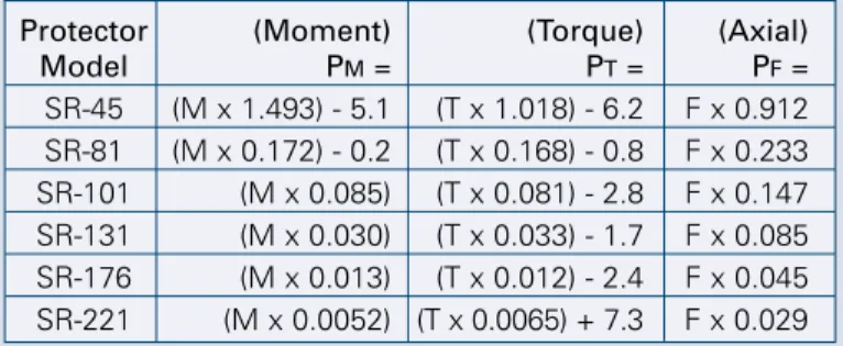
For a given model with known loads, the pressure setting required can be approximated from the following formula:
P = PM+ PT + PF
Where PM, PT, and PFare the pressure components
related to the moment, torque, and force load compo-nents expected at the break-away.
PM, PT, and PFare calculated using the formulas in
Tables 1 or 2, where M, T, and F are the expected loads at the set pressure break-away.
Example: For an SR-81 with a moment of 100 lb-in,
torque of 50 lb-in and an axial load of 20 lbs, and an acceleration of 2 G’s, the pressure setting is calculated as follows:
P=((100*0.172) - 0.2) + ((50*0.168) - 0.8) + (20*0.233) + ((100*2*0.172) - 0.2)
= 17 + 7.6 + 4.66 + 34.2 = 63.46
A nominal air pressure setting of 63 psi is required.
Protector (Moment) (Torque) (Axial)
Model PM= PT= PF= SR-45 (M x 1.493) - 5.1 (T x 1.018) - 6.2 F x 0.912 SR-81 (M x 0.172) - 0.2 (T x 0.168) - 0.8 F x 0.233 SR-101 (M x 0.085) (T x 0.081) - 2.8 F x 0.147 SR-131 (M x 0.030) (T x 0.033) - 1.7 F x 0.085 SR-176 (M x 0.013) (T x 0.012) - 2.4 F x 0.045 SR-221 (M x 0.0052) (T x 0.0065) + 7.3 F x 0.029
Table 1: Protector Pressure Setting Calculations (English Units: lb-in, psi, lb)
Protector (Moment) (Torque) (Axial)
Model PM= PT= PF= SR-45 (M x 0.9112) - 0.3 (T x 0.6214) - 0.4 F x 0.01414 SR-81 (M x 0.1052) (T x 0.1027) - 0.1 F x 0.00361 SR-101 (M x 0.0517) (T x 0.0495) - 0.2 F x 0.00228 SR-131 (M x 0.0183) (T x 0.0199) - 0.1 F x 0.00132 SR-176 (M x 0.0077) (T x 0.0075) - 0.2 F x 0.00070 SR-221 (M x 0.0032) (T x 0.0040) + 0.5 F x 0.00045
Table 2: Protector Pressure Setting Calculations (Metric Units: N-m, Bar, N)
MODEL SPECIFICATIONS
Specification Description SR-45 SR-81 SR-101 SR-131 SR-176 SR-221 Angular ±15° ±13° ±12° ±10° ±10° ±8° Displacement Torsional ±20° ±25° ±25° ±20° ±20° ±20° Displacement Axial 0.20 in 0.34 in 0.40 in 0.46 in 0.63 in 0.63 in Displacement (5 mm) (8.66 mm) (10.2 mm) (11.7 mm) (16 mm) (16 mm)Maximum Air 90 psi 90 psi 90 psi 90 psi 90 psi 90 psi
Pressure Setting (6.2 bar) (6.2 bar) (6.2 bar) (6.2 bar) (6.2 bar) (6.2 bar)
Weight .32 lb 1.28 lb 2.6 lb 5.1 lb 12.0 lb 25.1 lb
(0.15 kg) (0.58 kg) (1.2 kg) (2.3 kg) (5.4 kg) (11.4 kg)
Moment Break-away 65 lb-in 521 lb-in 1060 lb-in 3000 lb-in 7130 lb-in 17390 lb-in
@ 90 psi (6.2 bar) (7.2 N-m) (59.0 N-m) (120 N-m) (339 N-m) (806 N-m) (1965 N-m)
Torque Break-a way 95 lb-in 540 lb-in 1145 lb-in 2780 lb-in 7530 lb-in 13250 lb-in
@ 90 psi (6.2 bar) (10.7 N-m) (61.0 N-m) (130 N-m) (314 N-m) (851 N-m) (1497 N-m)
Axial Break-a way 100 lb 385 lb 610 lb 1060 lb 2000 lb 3100 lb
@ 90 psi (6.2 bar) (440 N) (1713 N) (2713 N) (4715 N) (8900 N) (13800 N)
“The SR-45 crash protector has proven to be an invaluable addition to our automated equipment. The savings on down time and repairs is immeasurable.”
Daniel K. DiAndrea Project Engineer
ATI INDUSTRIAL AUTOMATION 5
“With the automatic reset feature, there is never a reason to enter the robot cell and realign tooling. Now, when an interference occurs, it is as simple as correcting the cause and restarting the equipment.”
Jeff Reust Automation Engineer BOSCH Automotive Brad Harrison Nano Connector Stem side interface plate (optional
in blank or custom configurations) Body side interface plate (optional in blank or custom configurations) Reset Spheres Sensor (normally closed) Energy absorbing piston Connector block (removable)
Sensitivity adjustment screw
Stem with
reset spheres attached
Note: The stem, cam and spheres are made of hardened tool steel.
Cam Channel for optional spring
PERFORMANCE DATA
0 20 40 60 80 100 0 20 30 40 50 60 70 80 90 Supply Pressure B reak A w ay L o a d lb-in Nm 2 4 6 8 10 psi bar 1 2 3 4 5 6 0 100 200 300 400 500 600 0 20 30 40 50 60 70 80 90 Supply Pressure B reak A way L o ad lb-in Nm psi bar 1 2 3 4 5 6 10 40 20 30 50 60 0 200 400 600 800 1000 1200 1400 0 20 30 40 50 60 70 80 90 Supply Pressure B reak A w ay L o ad lb-in Nm psi bar 1 2 3 4 5 6 20 40 60 80 100 120 140ATI INDUSTRIAL AUTOMATION 7 0 500 1000 1500 2000 2500 3000 3500 0 20 30 40 50 60 70 80 90 Supply Pressure B reak A w ay L o ad lb-in Nm psi bar 1 2 3 4 5 6 50 150 100 200 250 300 350 0 1000 2000 3000 4000 5000 6000 7000 8000 0 20 30 40 50 60 70 80 90
Supply Pre ssure
B re ak A w ay L o ad lb-in Nm psi bar 1 2 3 4 5 6 100 200 300 400 500 600 700 800 0 2000 4000 6000 8000 10000 12000 14000 16000 18000 20000 0 20 30 40 50 60 70 80 90 lb-in Nm psi bar 1 2 3 4 5 6 250 500 750 1000 1250 1500 1750 2000 2250 B re ak A w ay L o ad
Supply Pre ssure
9160- - -
-9160-045- -
-SR-81, SR-101, SR-131, SR-176 & SR-221
SR-45
C1: Flexible boot. SR-81, SR-101, SR-131, SR-176 & SR-221 Weld Spatter Shield. SR-81, SR-101, SR-131
(IP65 rated)
B: Blank Interface Plate (Body) S: Blank Interface Plate (Stem)
N: No Interface Plate T: Two blank Interface Plates (Body & Stem) SR-81 & SR-101 SR-131, SR-176 & SR-221
R: #10-32 (M5) Air Supply Port R: 1/8 NPT Air Supply Port [No other option] G: G 1/8 Air Supply Port BN: No cable
BB: High-flex cable with screw-on connector, 5M (16 ft.) long with flying leads BC: High-flex cable with 90
º
snap-on connector, 5M (16 ft.) long with flying leads BU: High-flex cable with snap-on connector, 5M (16 ft.) long with flying leads P00: No Spring Assist
P05: Spring assist of 5 psi pressure P10: Spring assist of 10 psi pressure P15: Spring assist of 15 psi pressure
081: SR-81 model 101: SR-101 model 131: SR-131 model 176: SR-176 model 221: SR-221 model
B: Blank Robot Adapter Plate (Stem Side) N: No Adapter Plate
R: Reset Option N: No Reset Option BN: No cable
BB: High-flex cable with screw-on connector, 5M (16 ft.) long with flying leads BC: High-flex cable with 90º snap-on connector, 5M (16 ft.) long with flying leads BU: High-flex cable with snap-on connector, 5M (16 ft.) long with flying leads P00: No Spring Assist
P05: Spring assist of 5 psi pressure P10: Spring assist of 10 psi pressure P15: Spring assist of 15 psi pressure C2:
ATI INDUSTRIAL AUTOMATION 9
9230-60-1005-08
9230-60-1030-12
ATI INDUSTRIAL AUTOMATION
ATI INDUSTRIAL AUTOMATION
w w w . a t i - i a . c o m
w w w . a t i - i a . c o m
Protector SR-45
9230-60-1031-09
9230-60-1032-08
ATI INDUSTRIAL AUTOMATION
ATI INDUSTRIAL AUTOMATION
w w w . a t i - i a . c o m w w w . a t i - i a . c o m Protector SR-101 Protector SR-131
ATI INDUSTRIAL AUTOMATION 11
9230-60-1033-10
9230-60-1034-08
ATI INDUSTRIAL AUTOMATION
ATI INDUSTRIAL AUTOMATION
w w w . a t i - i a . c o m w w w . a t i - i a . c o m Protector SR-176 Protector SR-221
Pinnacle Park 1031 Goodworth Drive Apex, NC 27539 USA +1 919.772.0115 +1 919.772.8259 fax E-mail: [email protected] www.ati-ia.com
Other ATI Products
Robotic/Automatic Tool Changer – Quick-Change
A high-precision rugged device that automatically changes tooling. Patented fail-safe locking mechanism uses No-Touch LockingTMtechnology, allowing plate separation when locking.
Robotic/Automatic Tool Changers for Heavy Automation
This series of modular tool changers are designed specifically for high-payload and high-moment appli-cations. Automatic Modulesto pass air, fluid, and electrical signals are also available for use in non-tool changer applications. Useful for processes requiring repeated connection/ disconnection of utilities.
Robotic and CNC Deburring Tools –
Speedeburr and Flexdeburr
These air-driven robotic tools cover a wide variety of automated deburring applications with fast cycle times and clean, accurate cuts. Flexdeburr is designed for removal of parting lines and flash, while Speedeburr is specially designed for edge deburring and chamfering.
Robotic Rotary Joint
A device that allows unlimited rotation of end-of-arm tooling without tangling or twisting robot lines. Utilizes advanced slip-ring technology to pass electrical and pneumatic signals from robot to tooling.
Multi-Axis Force/ Torque Sensor – F/T
Measures the full six components of force and torque. High overload protection and high signal-to-noise ratio. Used in robotic and research applications.
Automated Assembly Alignment Device –
Compensator
An insertion device using Remote Center Compliance technology that helps assembly machines automatically align close-fitting parts, preventing jamming and galling.
Company Profile
ATI Industrial Automation is a world-leading developer of Automatic Tool Changers, Multi-Axis Force/Torque Sensing Systems, Compliance Devices, Robotic Crash Protection Devices, Robotic Deburring Tools, and Robotic Rotary Joints. Our products are found in thousands of successful applications around the world.
Since 1982, our engineers have been developing cost-effective, state-of-the-art products and solutions to improve manufacturing productivity.
Our Mission is to provide customers around the world with high-quality robotic peripheral devices, tooling and sensors that enhance customer prof-itability by increasing the effectiveness, flexibility, safety and productivity of their automation applications. We accomplish this through continuous improvement of existing products, product customization and new product innovation.
Our engineering-centric staff focuses on providing customer solutions to robotic, automation and sensing applications.
Our Quality Policy
ATI Industrial Automation strives to provide customer satisfaction through continual improvement of on-time delivery, quality and reliability, and a constant focus on innovation and profitability.