Last Updated: July 7, 2011
Aeisha Duncan
Alex Nadimi
John George
About the Authors
Aeisha Duncan, Technical Marketing Engineer, Systems Architecture and
Strat-egy, Cisco Systems
Aeisha Duncan, CCIE #13455, is a Technical Marketing Engineer for data center technolo-gies in Cisco's Systems Architecture and Strategy group. Prior to joining the SASU team, Aeisha spent 4 years as a Customer Support Engineer in Cisco's Technical Assistance Cen-ter where she supported LAN switching, VPN and Firewall technologies. She earned a B.S. in Computer Science from the University of Maryland at Baltimore County and an M.S. in Computer Networking from North Carolina State University.
Alex Nadimi, Solutions Architect, Systems Architecture and Strategy, Cisco
Systems
Alex has been with Cisco for the past 15 years and is currently working as a Solutions Archi-tect in Cisco Systems ArchiArchi-tecture and Strategy group. Prior to this role, he worked as a Technical Marketing Engineer in the Cisco Central Marketing Organization. He has devel-oped solutions and technical guidance on various technologies such as security, VPN net-works, WAN transport technologies, data center solutions, and virtualization. Prior to Cisco, he has worked at Hughes LAN Systems and Northern Telecom. He holds a masters of sci-ence in electrical engineering from Louisiana State University.
John George, Reference Architect, Infrastructure and Cloud Engineering,
NetApp
John George is a Reference Architect in NetApp's Infrastructure and Cloud Engineering team and is focused on developing, validating, and supporting cloud infrastructure solutions that include NetApp products. Before his current role, he supported and administered Nortel's worldwide training network and VPN infrastructure. John holds a master's degree in computer engineering from Clemson University.
Lindsey Street
Mike Zimmerman
Wen Yul
Lindsey Street, Reference Architect, Infrastructure and Cloud Engineering,
NetApp
Lindsey Street is a systems architect in the NetApp Infrastructure and Cloud Engineering team. She focuses on the architecture, implementation, compatibility, and security of inno-vative vendor technologies to develop competitive and high-performance end-to-end cloud solutions for customers. Lindsey started her career in 2006 at Nortel as an interoperability test engineer, testing customer equipment interoperability for certification. Lindsey has her Bachelors of Science degree in Computer Networking and her Master's of Science in Infor-mation Security from East Carolina University.
Mike Zimmerman, Reference Architect, Infrastructure and Cloud Engineering,
NetApp
Mike Zimmerman is a reference architect in NetApp's Infrastructure and Cloud Engineering team. He focuses on the implementation, compatibility, and testing of various vendor tech-nologies to develop innovative end-to-end cloud solutions for customers. Zimmerman started his career at NetApp as an architect and administrator of Kilo Client, NetApp's inter-nal cloud infrastructure, where he gained extensive knowledge and experience building end-to-end shared architectures based upon server, network, and storage virtualization.
Wen Yu, Senior Infrastructure Technologist, VMware
Wen Yu is a Sr. Infrastructure Technologist at VMware, with a focus on partner enablement and evangelism of virtualization solutions. Wen has been with VMware for six years during which time four years have been spent providing engineering level escalation support for customers. Wen specializes in virtualization products for continuous availability, backup recovery, disaster recovery, desktop, and vCloud. Wen Yu is VMware, Red Hat, and ITIL cer-tified.
The CVD program consists of systems and solutions designed, tested, and documented to facili-tate faster, more reliable, and more predictable customer deployments. For more information visit http://www.cisco.com/go/designzone.
ALL DESIGNS, SPECIFICATIONS, STATEMENTS, INFORMATION, AND RECOMMENDATIONS (COLLECTIVELY, “DESIGNS”) IN THIS MANUAL ARE PRESENTED “AS IS,” WITH ALL FAULTS. CISCO AND ITS SUPPLIERS DIS-CLAIM ALL WARRANTIES, INCLUDING, WITHOUT LIMITATION, THE WARRANTY OF MERCHANTABILITY, FIT-NESS FOR A PARTICULAR PURPOSE AND NONINFRINGEMENT OR ARISING FROM A COURSE OF DEALING, USAGE, OR TRADE PRACTICE. IN NO EVENT SHALL CISCO OR ITS SUPPLIERS BE LIABLE FOR ANY INDIRECT, SPECIAL, CONSEQUENTIAL, OR INCIDENTAL DAMAGES, INCLUDING, WITHOUT LIMITATION, LOST PROFITS OR LOSS OR DAMAGE TO DATA ARISING OUT OF THE USE OR INABILITY TO USE THE DESIGNS, EVEN IF CISCO OR ITS SUPPLIERS HAVE BEEN ADVISED OF THE POSSIBILITY OF SUCH DAM-AGES.
THE DESIGNS ARE SUBJECT TO CHANGE WITHOUT NOTICE. USERS ARE SOLELY RESPONSIBLE FOR THEIR APPLICATION OF THE DESIGNS. THE DESIGNS DO NOT CONSTITUTE THE TECHNICAL OR OTHER PROFESSIONAL ADVICE OF CISCO, ITS SUPPLIERS OR PARTNERS. USERS SHOULD CONSULT THEIR OWN TECHNICAL ADVISORS BEFORE IMPLEMENTING THE DESIGNS. RESULTS MAY VARY DEPENDING ON FACTORS NOT TESTED BY CISCO.
The Cisco implementation of TCP header compression is an adaptation of a program developed by the Uni-versity of California, Berkeley (UCB) as part of UCB’s public domain version of the UNIX operating system. All rights reserved. Copyright © 1981, Regents of the University of California.
Cisco and the Cisco Logo are trademarks of Cisco Systems, Inc. and/or its affiliates in the U.S. and other coun-tries. A listing of Cisco's trademarks can be found at http://www.cisco.com/go/trademarks. Third party trade-marks mentioned are the property of their respective owners. The use of the word partner does not imply a partnership relationship between Cisco and any other company. (1005R)
Any Internet Protocol (IP) addresses and phone numbers used in this document are not intended to be actual addresses and phone numbers. Any examples, command display output, network topology diagrams, and other figures included in the document are shown for illustrative purposes only. Any use of actual IP addresses or phone numbers in illustrative content is unintentional and coincidental.
Deploying Enhanced Secure Multi-Tenancy into Virtualized Data Centers © 2011 Cisco Systems, Inc. All rights reserved.
Deploying Enhanced Secure Multi-Tenancy into
Virtualized Data Centers
Introduction
Enhanced Secure Multi-Tenancy Overview
The biggest obstacle to adoption of IT as a service (ITaaS) has been lack of confidence that data and applications are securely isolated in a cloud-based infrastructure, where servers, networks, and storage are all shared resources. Cisco®, VMware®, and NetApp® have jointly designed a best-in-breed Enhanced Secure Multi-Tenancy (ESMT) architecture and have validated this design in a lab environment. For more information, see the Enhanced Secure Multi-Tenancy Design Guide
(http://www.cisco.com/en/US/docs/solutions/Enterprise/Data_Center/Virtualization/securecldg_V2.ht ml).
This document provides detailed implementation information and examples from a lab-validated reference design. It is structured to provide server, network, and storage architects and engineers with the implementation details to deploy and secure multi-tenant environments on four pillars:
• Secure separation • Service assurance • Availability • Manageability
Note This deployment guide assumes an existing FlexPodTM for VMware Infrastructure is in place and has been properly configured.
FlexPod Overview
FlexPod for VMware is a validated “POD-like” configuration built with technologies and best practices from Cisco, NetApp, and VMware. FlexPod for VMware serves as a base infrastructure platform for many of the applications and solutions that customers deploy today. ESMT is one example of a solution
that can be layered on top of FlexPod for VMware. For more information on FlexPod for VMware and the other solutions that can be built on the infrastructure, see FlexPod for VMware Deployment Model (http://www.cisco.com/en/US/docs/solutions/Enterprise/Data_Center/Virtualization/flexpod_vmware.h tml).
Note NetApp TR-3892, FlexPod for VMware Implementation Guide, is available only to Cisco, NetApp, and VMware sales representatives or qualified FlexPod partners.
Security Framework
Secure separation within this architecture is implemented at all layers and within most devices. This “defense in depth” approach follows the methodology outlined in Cisco SAFE: A Security Reference Architecture
(http://www.cisco.com/en/US/solutions/collateral/ns170/ns896/ns954/white_paper_c11-527476.html).
Deployment Procedures
This section outlines the deployment procedures for the various components and devices of the ESMT architecture. The lab implementation used to validate the ESMT deployment included four tenants:
• Tenant 1—SharePoint • Tenant 2—Exchange • Tenant 3—SQL
• Tenant 50—Infrastructure
These applications were used to create tenants, however this document does not describe application deployment procedures. The Infrastructure tenant includes commonly shared resources such as Microsoft Active Directory® (AD) and a centralized syslog server.
Deploying the Cisco Nexus 7000
Figure 1 Layer 2 Deployment
Layer 2 Deployment
The Cisco Nexus® 7000 acts as the aggregation layer in the ESMT deployment, so it needs trunked links toward the access layer and the services chassis (Figure 1). The two Cisco Nexus 7000s deployed should be configured as virtual port channel (vPC) peers, with an EtherChannel acting as the vPC peer link. The following configuration snippet is for one peer in the vPC domain:
vpc domain 10 role priority 50
peer-keepalive destination 10.1.30.102 source 10.1.30.101 vrf vpc-mgmt peer-gateway
interface port-channel1
description *** Port Channel Between Aggregation - VPC Peer-Link; E1/17, E1/18 *** switchport
switchport mode trunk
switchport trunk native vlan 2
switchport trunk allowed vlan 2-3967,4048-4093 spanning-tree port type network
mtu 9000 vpc peer-link
Once vPC peering is established, a vPC should be configured going toward the access layer and the services chassis:
interface port-channel45
description *** Port Channel Between Aggregation and Access Switches E1/25, E1/26 *** switchport
switchport mode trunk
switchport trunk native vlan 2
switchport trunk allowed vlan 2,101,105-111,113,115,119-124,129-130 switchport trunk allowed vlan add 132,140,161-162,481,490-493,499-500 switchport trunk allowed vlan add 581-586,588-592,599-600,900-902 switchport trunk allowed vlan add 905
mtu 9000 291482 Aggregation Cisco Nexus 7000 Cisco VSS 1440 Cisco Nexus 5000 Services Access Compute
service-policy type queuing input ingress-queuing service-policy type queuing output egress-policy vpc 45
interface port-channel78
description *** Port Channel Between Agg and Services - E1/9, E/10 *** switchport
switchport mode trunk
switchport trunk native vlan 2
switchport trunk allowed vlan 2,51-53,57,90,99-102,111,116,125 switchport trunk allowed vlan add 131-132,161,166,494,586-587,594 switchport trunk allowed vlan add 597,902
logging event port link-status logging event port trunk-status mtu 9000
service-policy type queuing input ingress-queuing service-policy type queuing output egress-policy vpc 78
Layer 3 Deployment
Figure 2 Tenant 1 Topology
The Cisco Nexus 7000 acts as the Layer 3 gateway for all of the tenants. To ensure secure separation between the tenants, a Virtual Routing and Forwarding (VRF) instanceis configured for each tenant. There may be multiple Layer 3 interfaces in a VRF instanceto service different services and VLANs within a tenant.
291452
ten1-wfe1 .101
dc09-n7k1-1-vdcA (global routing instance)
dc09-n7k1-1-vdcA vrf-ten1 (DGW: 10.1.100.1) HSRP: 10.51.32.x/24 HSRP .254 .11 .12 .11 .12 dc07-acesm-1 ten1-vc1 VIP .100 dc07-ips4270-1 dc07-ips4270-2 Po 100 VLAN Pairing External to tenant: Failover VLAN: 2001: 10.200.1.x/24 State VLAN: 2002: 10.200.2.x/24 VLAN 103 VLAN 103 VLAN 102 VLAN 102 VLAN 101 VLAN 101 VLAN 104 VLAN 104 VLAN 51 VLAN 101 External to tenant: Fault Tolerant VLAN: 2003:
10.200.3.x/23
dc07-fwsm-1 ten1-vc1 (routed mode)
dc010-n7k1-1-vdcA (global routing instance)
dc10-n7k1-1-vdcA vrf-ten1 (DGW: 10.1.100.1) dc08-acesm-1 ten1-vc1 dc08-ips4270-1 dc08-ips4270-2 Po 100 VLAN Pairing dc08-fwsm-1 ten1-vc1 (routed mode) .3 .2 .20 .21 .252 HSRP: 10.1.100.x/24 .251 HSRP .1 HSRP: 10.1.101.x/24 HSRP .1 .3 .2 drs1-vsm1 VLAN 101 Tenant 1 vShield Edge NAT: 10.x.102.51/25 APP OS ten1-wfe2 .102 APP OS ten1-app1 .103 APP OS smt-ad1 .101 APP OS smt-ad2 .102 APP OS ten1-sql1 .104 APP OS Tenant 50 VLAN 591
vrf context vrf-ten1
ip route 0.0.0.0/0 10.1.100.1 ---' Inter-tenant routing goes through FWSM in services chassis
interface Vlan101 vrf member vrf-ten1 no ip redirects
ip address 10.1.101.3/24 ip router ospf 1 area 0.0.0.0 hsrp version 2
hsrp 101
authentication text c1sc0 preempt delay minimum 180 priority 110
timers 1 3 ip 10.1.101.1 no shutdown mtu 9216
description **SVI for ten1**
interface Vlan102 vrf member vrf-ten1 no ip redirects ip address 10.1.100.252/24 hsrp version 2 hsrp 102 authentication text c1sc0 preempt delay minimum 180 timers 1 3
ip 10.1.100.254 no shutdown
mtu 9216
description ** FireWall Inside ***
interface Vlan106 vrf member vrf-ten1 no ip redirects
ip address 10.1.102.3/24 ip ospf passive-interface ip router ospf 1 area 0.0.0.0 hsrp version 2
hsrp 106
authentication text c1sc0 preempt delay minimum 180 timers 1 3
ip 10.1.102.1 no shutdown
description ** SVI for Tenant 1 Storage Services **
interface Vlan107 vrf member vrf-ten1 no ip redirects ip address 10.1.107.3/25 hsrp version 2 hsrp 107 authentication text c1sc0 preempt delay minimum 180 priority 110
timers 1 3 ip 10.1.107.1 no shutdown
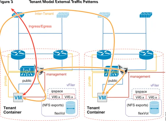
Figure 3 Tenant Model External Traffic Patterns
Inter-tenant routes are not propagated to the tenant VRF instances. Inter-tenant routing is handled by the Cisco Firewall Switching Module (FWSM) deployed in the services chassis. Packets destined to another VRF instance or tenant are routed to the FWSM which, in turn, routes them to the global routing table. Static routes to each VRF instance are added to the global routing table. The routes point to the outside interface of the virtual context on the FWSM that belongs to that particular tenant.
ip route 10.1.101.0/25 10.51.32.1 ---' 10.51.32.1 is the outside interface of the ten1-vc on the FWSM
Figure 4 Core-Aggregation Connections
Tenant
Container TenantContainer
vFiler Vif0.x Vif0.x ipspace flexVol flexVol private management Inter-Tenant Ingress/Egress vFiler Vif0.x Vif0.x ipspace public public pr iv at e management (NFS exports) (NFS exports)
VM
291453VM
291447 Core DC #1 Aggregation DC #1 Eth 1/17 core11-n7k-1 (VDC:vdca) dc09-n7k-1 (VDC:vdca) Eth 1/18 Eth 1/2.3501 Eth 1/1 10.1.30.x/30 Eth 1/1.3451 10.1.31.x/30 Eth 1/2 Eth 1/17 Eth 1/18 Po1 Po1 Eth 1/1.3401 Eth 1/2.3551 Eth 1/1 Eth 1/2 Eth 1/25 Eth 1/26 Eth 1/25 Eth 1/26 10.1.30.x/30 .5 .1 .1 .5 10.1.31.x/30 .2 .6To reach clients that are in the VRF instance but not in the local subnets, routing to the core is needed. A trunk with Layer 3 point-to-point links is configured on the links going to both cores. Each
point-to-point link belongs to a particular VRF instance/tenant and is used as the gateway to these clients.
interface Ethernet1/1.3401
description *** Connection to CORE11-N7K-1 vrf-ten1 *** encapsulation dot1q 3401
vrf member vrf-ten1
ip flow monitor NETFLOW input ip flow monitor NETFLOW output ip address 10.1.30.2/30
ip ospf authentication
ip ospf authentication key-chain RoutingAuth ip router ospf 1 area 0.0.0.0
no shutdown
For most cases, static routing is sufficient for intra- and inter-tenant traffic. For tenants requiring a more robust routing protocol, OSPF is used.
router ospf 1 vrf vrf-ten1
area 0.0.0.0 range 10.1.101.0/25
Hardening the Cisco Nexus 7000
In the following example, the Cisco Nexus 7000 can be hardened to allow access only through SSH, FTP, and ICM in the inbound access list. The outbound access list allows access only to the OOB management network and the inside network. More information on the Cisco Nexus 7000 security capabilities and general hardening guidance can be found at:
http://www.cisco.com/en/US/docs/switches/datacenter/sw/4_2/nx-os/security/configuration/guide/Cisc o_Nexus_7000_NX-OS_Security_Configuration_Guide__Release_4.2.pdf.
ip access-list OBB-inbound
3 permit tcp 172.26.162.216/32 172.26.162.68/32 9 permit ip 172.26.162.214/32 172.26.162.68/32
10 permit icmp 172.26.162.0/16 172.26.162.68/32 ttl-exceeded 20 permit icmp 172.26.162.0/16 172.26.162.68/32 port-unreachable 30 permit icmp 172.26.162.0/16 172.26.162.68/32 echo-reply 40 permit icmp 172.26.162.0/16 172.26.162.68/32 echo 50 permit tcp 172.26.0.0/16 172.26.162.68/32 eq 22 60 permit tcp 64.102.0.0/16 172.26.162.68/32 eq 22 61 permit tcp 64.0.0.0/8 172.26.162.68/32 eq 22 62 permit tcp 10.0.0.0/8 172.26.162.68/32 eq 22 70 permit tcp 172.26.162.10/32 eq ftp 172.26.162.68/32 gt 1023 established 80 permit tcp 172.26.162.10/32 eq ftp-data 172.26.162.68/32 gt 1023 90 permit tcp 172.26.162.0/32 gt 1023 172.26.162.68/32 gt 1023 established 100 permit udp 172.26.162.0/16 gt 1023 172.26.162.68/32 gt 1023
102 permit udp 172.26.162.6/32 any eq ntp 103 permit udp 172.26.162.9/32 any eq ntp 110 deny ip any any log
ip access-list OBB-outbound
10 permit ip 172.26.162.68/32 172.26.0.0/16 20 permit ip 172.26.162.68/32 64.102.0.0/16 21 permit ip 172.26.162.68/32 64.0.0.0/8 22 permit ip 172.26.162.68/32 10.0.0.0/8
The access list can be applied to the management interface as follows:
interface mgmt0
ip access-group OBB-inbound in ip access-group OBB-outbound out
vrf member management ip address 172.26.162.68/16
Service Assurance Deployment
Queuing and bandwidth control on the Cisco Nexus 7000 is implemented in much the same way as it is implemented on the Cisco Nexus 5000. Egress queuing is used, however ingress queuing can be employed where it is understood that the traffic coming in is marked correctly and trusted. This is the case for this deployment. For bridged traffic CoS is untouched, while for routed traffic DSCP is copied to the CoS value.
You may also have to change the default mapping of cos-to-queue for this platform, as is the case in this deployment. It is changed to more closely resemble the mapping in the Cisco Unified Computing SystemTM (UCS) and Cisco Nexus 5000 so bandwidth allocation can be consistent among the different platforms. The cos-to-queue map must be configured in the default VDC of the Cisco Nexus 7000. Queue names beginning with 8q2t-in-q correspond to ingress queues for 10Gbps ports, while queue names beginning with 1p7q4t-out-q correspond to egress queues for these ports:
DC09-N7K-1# show class-map type queuing Type queuing class-maps
========================
class-map type queuing match-any 8q2t-in-q2
Description: Classifier for ingress queue 2 of type 8q2t match cos 2
class-map type queuing match-any 8q2t-in-q3
Description: Classifier for ingress queue 3 of type 8q2t
class-map type queuing match-any 8q2t-in-q4
Description: Classifier for ingress queue 4 of type 8q2t match cos 4
class-map type queuing match-any 8q2t-in-q5
Description: Classifier for ingress queue 5 of type 8q2t match cos 5
class-map type queuing match-any 8q2t-in-q6
Description: Classifier for ingress queue 6 of type 8q2t match cos 6
class-map type queuing match-any 8q2t-in-q7
Description: Classifier for ingress queue 7 of type 8q2t
class-map type queuing match-any 8q2t-in-q-default
Description: Classifier for ingress default queue of type 8q2t match cos 0-1,3
class-map type queuing match-any 1p7q4t-out-q2
Description: Classifier for egress queue 2 of type 1p7q4t match cos 2
class-map type queuing match-any 1p7q4t-out-q3
Description: Classifier for egress queue 3 of type 1p7q4t
class-map type queuing match-any 1p7q4t-out-q4
Description: Classifier for egress queue 4 of type 1p7q4t match cos 4
class-map type queuing match-any 1p7q4t-out-q5
Description: Classifier for egress queue 5 of type 1p7q4t match cos 5
class-map type queuing match-any 1p7q4t-out-q6
Description: Classifier for egress queue 6 of type 1p7q4t match cos 6
class-map type queuing match-any 1p7q4t-out-q7
Description: Classifier for egress queue 7 of type 1p7q4t
class-map type queuing match-any 1p7q4t-out-q-default
Description: Classifier for egress default queue of type 1p7q4t match cos 0-1,3
These class maps can then be used for queuing and bandwidth control service polices to be applied to selected ports:
DC09-N7K-1-vdcA# sh policy-map type queuing ingress-queuing
Type queuing policy-maps ========================
policy-map type queuing ingress-queuing class type queuing 8q2t-in-q2
bandwidth percent 25 class type queuing 8q2t-in-q4 bandwidth percent 15 class type queuing 8q2t-in-q5 bandwidth percent 20 class type queuing 8q2t-in-q6 bandwidth percent 15
class type queuing 8q2t-in-q-default bandwidth percent 25
DC09-N7K-1-vdcA# sh policy-map type queuing egress-policy
Type queuing policy-maps ========================
policy-map type queuing egress-policy class type queuing 1p7q4t-out-q2 bandwidth percent 25
class type queuing 1p7q4t-out-q4 bandwidth percent 15
class type queuing 1p7q4t-out-q5 bandwidth percent 20
class type queuing 1p7q4t-out-q-default bandwidth percent 25
These policies are then applied to ports attaching to the access layer and the core layer:
interface port-channel45
description *** Port Channel Between Aggregation and Access Switches E1/25, E1/26 *** switchport
switchport mode trunk
switchport trunk native vlan 2
switchport trunk allowed vlan 2,101,105-111,113,115,119-124,129-130 switchport trunk allowed vlan add 132,140,161-162,481,490-493,499-500 switchport trunk allowed vlan add 581-586,588-592,599-600,900-902 switchport trunk allowed vlan add 905
mtu 9000
service-policy type queuing input ingress-queuing service-policy type queuing output egress-policy vpc 45
DC09-N7K-1-vdcA# sh run int e1/1
!Command: show running-config interface Ethernet1/1 !Time: Wed May 25 23:32:49 2011
version 5.1(3)
interface Ethernet1/1
description *** DC09-N7K-1 E1/1 To CORE11-N7K-1 E1/1 *** rate-mode dedicated force
udld disable
service-policy type queuing output egress-policy service-policy type queuing input ingress-queuing no shutdown
Deploying the Services Chassis
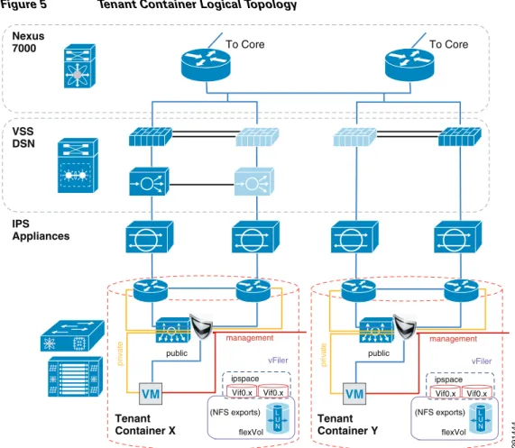
In a multi-tenant environment, different tenants may require different levels of network services security protection. Tenants with very stringent security requirements require a host of virtual and physical appliances to satisfy their needs, while other tenants may require basic network protection. This architecture implements Cisco FWSM, Cisco Application Control Engine (ACE), and Cisco Intrusion Prevention System (IPS) within the services segment of the architecture. It is important to note the flexible nature of this architecture, where the network architect can use any combination of security appliances to create their own security offerings. Some of these offerings are foundational, while the others are optional. Cisco ACE load balancer is considered optional, while it is recommended that IPS and FWSM firewall module be implemented for every tenant, as shown in Figure 5.
Figure 5 Tenant Container Logical Topology
The ACE/FWSM and IPS services are employed external to each tenant’s VRF instances. All these services are deployed in Layer 2 transparent mode. Additional information about services integration includes:
• Global routing instance resides on the Cisco Nexus 7000.
• Virtual Switching System (VSS) Domain Services Node (DSN) houses service modules. • Virtual IPS appliances are positioned inline.
• IPS allows each tenant to create and enforce their own security policy and IPS is tuned to reduce false positives.
More information on the specific deployment steps for FWSM, IPS, and ACE are outlined in Deploying the Cisco Firewall Switching Module in the Network, Deploying the Cisco Intrusion Prevention System, and Deploying the Cisco Application Control Engine.
Deploying Services with Redundancy
Services can be deployed in a redundant manner. ACE and FWSM can be deployed by using a separate logical link between them within a VSS domain. A VSS domain is used to provide a single services domain with redundant chassis, as shown in Figure 6.
Tenant
Container X TenantContainer Y
Nexus 7000 To Core To Core IPS Appliances VSS DSN vFiler Vif0.x Vif0.x ipspace flexVol flexVol private management vFiler Vif0.x Vif0.x ipspace public public pr iv at e management (NFS exports) (NFS exports) VM VM L U N L U N 291444
Figure 6 Single Services Domain with VSS
• Service modules leverage Virtual Switch Link (VSL) as data and control paths. • VLAN interfaces are assigned to the modules through the supervisor.
This allows multiple VLAN interfaces to support multiple virtual contexts.
• The autostate feature alerts modules to a state change of the VLAN on the supervisor. Use this feature when multiple paths exist for the VLAN.
The relevant configuration is:
svclc autostate
svclc multiple-vlan-interfaces
svclc switch 1 module 8 vlan-group 8,116,162 svclc switch 2 module 8 vlan-group 8,116,162 svclc vlan-group 8 2,101-103,111,2003 svclc vlan-group 116 116,117
svclc vlan-group 162 162 firewall autostate
firewall multiple-vlan-interfaces
firewall switch 1 module 7 vlan-group 7,9,116,162 firewall switch 2 module 7 vlan-group 7,9,116,162 firewall vlan-group 7 51-53,90,99,100,104,125,2001,2002 firewall vlan-group 9 57,166,494,586,587,594,597
analysis switch 1 module 9 management-port access-vlan 162 analysis switch 2 module 9 management-port access-vlan 162
Integration of Services Chassis
The services chassis is connected to the aggregation layer, as shown in Figure 7.
291448 10.200.1.x/24 Po2 Po1 10.200.2.x/24 10.200.3.x/24 .11 .12 .11 .12 .12 .11 dc07-ace-1 Slot:8
Failover link (VLAN 2001) Fast-hello dual-active
detection
Failover link (VLAN 2003) State link (VLAN 2002)
fwsm-1 Slot: 7
dc08-ace-1 Slot:8
dc07-nam
Slot:9 dc08-namSlot:9
fwsm-1 Slot: 7 VSS Domain dc08-c6500-1 VSS ID:1 dc07-c6500-1 VSS ID:2 VSL Link Eth 2/1/8 Eth 2/5/4 G/2/2/47 G/1/2/47 Eth 1/1/8 Eth 1/5/4
Figure 7 Aggregation-Services Chassis Connectivity
The specific network topology used for validation of the network and services chassis is shown in Figure 8. 291883 Aggregation DC #1 Services DC #1 dc09-n7k-1 (VDC:vdca) dc08-c6500-1 VSS ID: 1 dc07-c6500-1 VSS ID: 2 dc10-n7k-1 (VDC:vdca) Eth 1/10 Eth 1/1/1 Eth 1/9 Eth 2/5/5 Po1 Po1 Po2 VSL Link Eth 1/25 Eth 1/26 Eth 1/37 Eth 1/39 Eth 1/25 Eth 1/26 Eth 1/25 Eth 1/26 Eth 2/1/8 Eth 1/1/8 Eth 2/5/4 Eth 1/5/4 G/2/2/47 G/1/2/47
Figure 8 SharePoint Tenant Logical Topology
Hardening the Services Chassis
The security hardening deployment steps and general hardening guidelines are defined in:
291452
ten1-wfe1 .101
dc09-n7k1-1-vdcA (global routing instance)
dc09-n7k1-1-vdcA vrf-ten1 (DGW: 10.1.100.1) HSRP: 10.51.32.x/24 HSRP .254 .11 .12 .11 .12 dc07-acesm-1 ten1-vc1 VIP .100 dc07-ips4270-1 dc07-ips4270-2 Po 100 VLAN Pairing External to tenant: Failover VLAN: 2001: 10.200.1.x/24 State VLAN: 2002: 10.200.2.x/24 VLAN 103 VLAN 103 VLAN 102 VLAN 102 VLAN 101 VLAN 101 VLAN 104 VLAN 104 VLAN 51 VLAN 101 External to tenant: Fault Tolerant VLAN: 2003:
10.200.3.x/23
dc07-fwsm-1 ten1-vc1 (routed mode)
dc010-n7k1-1-vdcA (global routing instance)
dc10-n7k1-1-vdcA vrf-ten1 (DGW: 10.1.100.1) dc08-acesm-1 ten1-vc1 dc08-ips4270-1 dc08-ips4270-2 Po 100 VLAN Pairing dc08-fwsm-1 ten1-vc1 (routed mode) .3 .2 .20 .21 .252 HSRP: 10.1.100.x/24 .251 HSRP .1 HSRP: 10.1.101.x/24 HSRP .1 .3 .2 drs1-vsm1 VLAN 101 Tenant 1 vShield Edge NAT: 10.x.102.51/25 APP OS ten1-wfe2 .102 APP OS ten1-app1 .103 APP OS smt-ad1 .101 APP OS smt-ad2 .102 APP OS ten1-sql1 .104 APP OS Tenant 50 VLAN 591
• Cisco SAFE: A Security Reference Architecture
http://www.cisco.com/en/US/solutions/collateral/ns170/ns896/ns954/white_paper_c11-527476.ht ml
• Network Security Baseline
http://www.cisco.com/en/US/docs/solutions/Enterprise/Security/Baseline_Security/securbase.pdf
Deploying the Cisco Nexus 5000
The basic Cisco Nexus 5000 configuration can be found in FlexPod for VMware Deployment Model (http://www.cisco.com/en/US/docs/solutions/Enterprise/Data_Center/Virtualization/flexpod_vmware.h tml). Cisco Nexus 5000 configurations for QoS and security hardening are shown in the sections that follow.
QoS Configuration on the Cisco Nexus 5000
For storage traffic originating on the Cisco Nexus 5000, classification is required to guarantee an acceptable service level for the traffic. This traffic can be classified with a global QoS policy on the Cisco Nexus 5000 and assigned to a system class:
ip access-list classify_COS_5 10 permit ip 192.168.98.100/32 any 20 permit ip 10.49.32.10/32 any 30 permit ip any 192.168.98.100/32 40 permit ip any 10.49.32.10/32
class-map type qos match-any Platinum_Traffic match access-group name classify_COS_5
policy-map type qos Global_Classify_NFS_Application class Platinum_Traffic
set qos-group 2
The other CoS values that are configured via port-profiles on the Cisco Nexus 1000V must be put into system classes on the Cisco Nexus 5000 to allow for bandwidth control and queuing within the Cisco Nexus 5000 switching fabric.
class-map type qos match-any Platinum_Traffic match access-group name classify_COS_5 class-map type qos match-any Gold_Transactional match cos 6
class-map type qos match-any Bronze_Transactional match cos 2
class-map type qos match-any Silver_Transactional match cos 4
class-map type qos match-any Platinum_Transactional match cos 5
policy-map type qos Global_Classify_NFS_Application class Platinum_Traffic set qos-group 2 class Platinum_Transactional set qos-group 2 class Gold_Transactional set qos-group 3 class Silver_Transactional set qos-group 4 class Bronze_Transactional set qos-group 5
On the Cisco Nexus 5000, a queuing policy is applied globally to the output of all interfaces on the switch. Classification for each qos-group or system class is done by the aforementioned policy-map Global_Classify_NFS_Application.
class-map type queuing Gold_Traffic_Q match qos-group 3
class-map type queuing class-all-flood match qos-group 2
class-map type queuing Bronze_Traffic_Q match qos-group 5
class-map type queuing Silver_Traffic_Q match qos-group 4
class-map type queuing Platinum_Traffic_Q match qos-group 2
class-map type queuing class-ip-multicast match qos-group 2
policy-map type queuing Global_BW_Queuing class type queuing Platinum_Traffic_Q priority
bandwidth percent 20
class type queuing Gold_Traffic_Q bandwidth percent 20
class type queuing Silver_Traffic_Q bandwidth percent 20
class type queuing Bronze_Traffic_Q bandwidth percent 15
class type queuing class-fcoe bandwidth percent 15
class type queuing class-default bandwidth percent 10
system qos
service-policy type queuing output Global_BW_Queuing
Hardening the Cisco Nexus 5000
In the following example, the Cisco Nexus 5000V can be hardened to allow access only through SSH, FTP, and ICM in the inbound access list. The outbound access list allows access only to the OOB management network and the inside network. More information on the Cisco Nexus 5000 security capabilities and general hardening guidance can be found at:
http://www.cisco.com/en/US/docs/switches/datacenter/nexus5000/sw/security/502_n2_1m/b_Cisco_n5 k_security_config_gd_rel_502_n2_1.pdf.
ip access-list OBB-inbound
3 permit tcp 172.26.162.216/32 172.26.162.28/32 9 permit ip 172.26.162.214/32 172.26.162.28/32
10 permit icmp 172.26.162.0/16 172.26.162.28/32 ttl-exceeded 20 permit icmp 172.26.162.0/16 172.26.162.28/32 port-unreachable 30 permit icmp 172.26.162.0/16 172.26.162.28/32 echo-reply 40 permit icmp 172.26.162.0/16 172.26.162.28/32 echo 50 permit tcp 172.26.0.0/16 172.26.162.28/32 eq 22 60 permit tcp 64.102.0.0/16 172.26.162.28/32 eq 22 61 permit tcp 10.0.0.0/8 172.26.162.28/32 eq 22 70 permit tcp 172.26.162.10/32 eq ftp 172.26.162.28/32 gt 1023 established 80 permit tcp 172.26.162.10/32 eq ftp-data 172.26.162.28/32 gt 1023 90 permit tcp 172.26.162.0/32 gt 1023 172.26.162.28/32 gt 1023 established 100 permit udp 172.26.162.0/16 gt 1023 172.26.162.28/32 gt 1023 120 permit tcp 172.26.162.214/32 eq tacacs 172.26.162.28/32 ip access-list OBB-outbound 10 permit ip 172.26.162.28/32 172.26.0.0/16 20 permit ip 172.26.162.28/32 64.102.0.0/16 30 permit ip 172.26.162.28/32 10.0.0.0/8
The access list can be applied to the management interface as follows
interface mgmt0
ip access-group OBB-inbound in ip access-group OBB-outbound out ip address 172.26.162.28/16
Deploying the Cisco Nexus 1010 and 1000V
In this deployment the combination of Cisco Nexus 1010 and Cisco Nexus 1000V are used to implement virtual switching at the access layer. For redundancy a pair of Cisco Nexus 1010 virtual appliances were configured. An active/passive pair of Cisco Nexus 1000V virtual service modules were configured within the Cisco Nexus 1010. All vSphereTM networking is configured to use a Cisco Nexus 1000V virtual switch, including VM, NFS, and vMotion traffic. The Cisco Nexus 1010s are logically connected to the Cisco Nexus 5000 access layer switches, as shown in Figure 9.
Figure 9 Cisco Nexus 1010 Integration and Logical Connectivity
Classification Using the Cisco Nexus 1000V
In this deployment, classification is done on the Cisco Nexus 1000V. Certain port-profiles are marked with a designated CoS value through a service policy attached to the service profile. Any marking done by the host is ignored. This CoS value is in turn trusted by the virtual interface card on the Cisco UCS server blade. CoS values were assigned in the following fashion:
drs1-vsm1# show policy-map Silver_CoS_4
291446 Aggregation DC #1 Access DC #1 dc09-n7k-1 (VDC:vdca) dc04-n5k-1 dc05-n5k-1 dc04-n1010-1 dc05-n1010-1 dc10-n7k-1 (VDC:vdca) Eth 1/26 Eth 1/37 Eth 1/25 Eth 1/39 Po1 Po1 Po103 Po102 Po101 Po104 Eth 1/25 Eth 1/26 Eth 1/37 Eth 1/39 Eth 1/25 Eth 1/26 Eth 1/25 Eth 1/26 Eth 1/38 Eth 1/38 Eth 1/40 Eth 1/40 4 4 3 5 4 2 1 1 2 6 3 3 3 5 4 6
Type qos policy-maps ====================
policy-map type qos Silver_CoS_4 class class-default
set cos 4
port-profile type vethernet vMotion_192_168_1 vmware port-group
switchport mode access switchport access vlan 901 ip flow monitor NFMonitor input ip flow monitor NFMonitor output
service-policy type qos input Silver_CoS_4 no shutdown
state enabled
Deploying Traffic Engineering with MAC-Pinning
Mac-pinning is implemented on the Cisco Nexus 1000V to fully utilize the redundant fabric uplinks. Port-profiles assigned to the same CoS value are split evenly between the two uplinks with static mac-pinning.
port-profile type vethernet Exch_NFS_192_168_120 vmware port-group
switchport mode access switchport access vlan 120 ip flow monitor NFMonitor input ip flow monitor NFMonitor output
service-policy type qos input Platinum_CoS_5
pinning id 0 ?--- Fabric A no shutdown
state enabled
port-profile type vethernet Infra_NFS_192_168_100 vmware port-group
switchport mode access switchport access vlan 600 ip flow monitor NFMonitor input ip flow monitor NFMonitor output
service-policy type qos input Platinum_CoS_5 pinning id 1 ?--- Fabric B no shutdown
state enabled
The uplink port-profile must be configured to honor the mac-pinning and implement dynamic mac-pinning when necessary:
port-profile type ethernet VIC-vm-data-uplink vmware port-group
switchport mode trunk
switchport trunk allowed vlan 101,105-107,111,113,115,122,124,132,161,592-593 channel-group auto mode on mac-pinning ?--- Mac-pinning enabled
no shutdown state enabled
Deploying the Cisco Firewall Switching Module in the Network
The FWSM is logically located between the global interface and the VRF interfaces for each tenant. FWSM is deployed in a bridged mode with different contexts for each tenant. Figure 10 shows the FWSM implemented within the services layer.
Figure 10 Integration of FWSM within Services Layer
The following design principles are implemented in FWSM in the ESMT topology:
• The default gateway for tenant VMs is the Cisco Nexus 7000 VRF instance HSRP address. Each tenant has its own VLAN and associated subnet assignments. For example:
– Tenant 1: 10.1.x.x/25
– Tenant 2: 10.2.x.x/25
– Tenant 50: 10.50.x.x/25
• A static route from VRF points to a firewall virtual context “inside” address. Additional services may be positioned but not detailed.
• There is a static route from each firewall instance to the Cisco Nexus 7000 global routing table. • OSPF prefix-list injects routes into area.
The basic configuration for tenant-1 (SharePoint) is:
hostname ten1-vc1 ! interface Vlan104 nameif inside security-level 100 ip address 10.1.100.1 255.255.255.0 standby 10.1.100.101 ! interface Vlan51 Services Firewall Virtual Contexts Nexus 7000 Global Routing Firewall Instances DGW: HSRP .254 VRF Instances DGW: HSRP .1 VRF Instances DGW: HSRP .1 291450 Tenant Container 3 VM L U N Tenant Container 50 VM L U N Tenant Container 1 VM L U N Tenant Container 2 VM L U N
nameif outside security-level 0 ip address 10.51.32.1 255.255.255.0 standby 10.51.32.2 ! mtu outside 1500 mtu inside 1500
icmp permit any outside icmp permit any inside no asdm history enable arp timeout 14400 nat-control
static (inside,outside) 10.1.101.0 10.1.101.0 netmask 255.255.255.128 static (inside,outside) 10.1.100.0 10.1.100.0 netmask 255.255.255.0 route outside 0.0.0.0 0.0.0.0 10.51.32.254 1
route inside 10.1.101.0 255.255.255.128 10.1.100.254 1
Deploying the Cisco Adaptive Security Device Manager for Management of Firewall Module
For information on the steps necessary to deploy the Cisco Adaptive Security Device Manager (ASDM) to mange the firewall module, see:
http://www.cisco.com/en/US/docs/security/asdm/6_2/user/guide/asdmug.pdf.
Deploying the Cisco Intrusion Prevention System
The Cisco IPS is deployed as an inline device and a separate context is used for each tenant. The IPS location within the services network is shown in Figure 8. The IPS can be configured using the CLI or the Cisco IPS Device Manager (IDM). In the configuration below, VLAN 103 and 104 are used by the IPS to provide inline intrusion protection within the SharePoint tenant. The CLI configuration is:
subinterface-type inline-vlan-pair subinterface 1 description to dc07-c6500-1 ten1/2 vlan1 103 vlan2 104 exit exit exit physical-interfaces TenGigabitEthernet7/1 description to dc08-c6500-1 ten1/2 admin-state enabled duplex auto speed auto default-vlan 1 alt-tcp-reset-interface none subinterface-type inline-vlan-pair subinterface 1 description to dc08-c6500-1 ten1/2 vlan1 103 vlan2 104 exit service analysis-engine virtual-sensor vs0
description Tenant1 Virtual Sensor anomaly-detection
operational-mode detect exit
physical-interface TenGigabitEthernet7/0 subinterface-number 1 physical-interface TenGigabitEthernet7/1 subinterface-number 1
inline-TCP-session-tracking-mode virtual-sensor inline-TCP-evasion-protection-mode strict
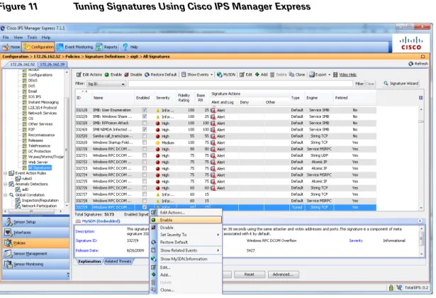
Once basic IPS networking parameters are configured, the IPS signatures can be tuned. Figure 11 shows how signatures can be tuned using Cisco IPS Manager Express (IME).
1. Go to the Configurations/Policies pane and click All Signatures. 2. Select the signature you want to tune, right click, and click Enable. 3. You can choose the actions and severity levels using the same procedure.
Figure 11 Tuning Signatures Using Cisco IPS Manager Express
For more information on configuring IPS using Cisco IME or CLI, see:
http://www.cisco.com/en/US/docs/security/ips/7.0/configuration/guide/ime/ime_interfaces.html.
Hardening the Cisco Intrusion Prevention System
Telnet can be disabled on the management interface and management access can be limited to certain subnets, as shown below.
network-settings host-ip 172.26.162.52/23,172.26.162.1 host-name dc08-ips4270-1 telnet-option disabled access-list 10.0.0.0/8 access-list 64.0.0.0/8 access-list 172.0.0.0/8
SSH should be configured as a means to access the CLI on IPS4270. The following link outlines the steps to configure SSH and other security parameters:
Installing and Using Cisco IPS Manager Express
For information on installing and using Cisco IPS Manager Express, see: http://www.cisco.com/en/US/docs/security/ips/trash/book_files/CLI7_1.pdf.
Deploying the Cisco Application Control Engine
The Cisco ACE module provides load balancing capability. In this deployment, ACE is configured to load balance between two front end servers 10.1.101.101 and 10.1.101.102 within the tenant-1 SharePoint tenant. The virtual interface address (VIP) is 10.1.100.100. ACE is also bridging between VLAN 102 and 103. The configuration for context ten1-vc-1 is shown in Figure 12.
Figure 12 Integration of ACE within Services Layer
The CLI for the ACE configuration is:
dc08-ace-1/Admin# changeto ten1-vc1 dc08-ace-1/ten1-vc1# sh running-config Generating configuration....
logging enable logging buffered 7
access-list BPDU ethertype permit bpdu
Tenant-1 Nexus 7000 To Core IPS Appliances private management public 10.1.101.101/102 VM VM 291485
access-list IPANYANY line 5 extended permit ip any any access-list IPANYANY line 6 extended permit icmp any any
probe tcp IIS interval 2 faildetect 2
passdetect interval 10 passdetect count 2 probe icmp PING interval 2 faildetect 2
rserver host real1
ip address 10.1.101.101 inservice
rserver host real2
ip address 10.1.101.102 inservice
serverfarm host farm1 predictor leastconns probe IIS probe PING rserver real1 inservice rserver real2 inservice
parameter-map type http PM-REUSE server-conn reuse
case-insensitive
parameter-map type connection timeouts set tcp timeout embryonic 10
set tcp ack-delay 400
sticky ip-netmask 255.255.255.255 address both group1 timeout 720
timeout activeconns replicate sticky serverfarm farm1
class-map match-all sp-vip
2 match virtual-address 10.1.100.100 any
policy-map type loadbalance first-match lbpol class class-default
sticky-serverfarm group1
policy-map multi-match LBPOL class sp-vip
loadbalance vip inservice loadbalance policy lbpol
loadbalance vip icmp-reply active connection advanced-options timeouts
service-policy input LBPOL interface vlan 102
bridge-group 1
access-group input BPDU access-group input IPANYANY no shutdown
interface vlan 103 bridge-group 1
access-group input BPDU access-group input IPANYANY no shutdown interface bvi 1 ip address 10.1.100.21 255.255.255.0 alias 10.1.100.22 255.255.255.0 peer ip address 10.1.100.20 255.255.255.0 no shutdown ip route 10.1.101.0 255.255.255.0 10.1.100.254 ip route 0.0.0.0 0.0.0.0 10.1.100.1
Hardening the Cisco Application Control Engine
The ACE management interface can be hardened by implementing a policy map and assigning it to the interface, as shown below. More information on security hardening commands on the ACE module can be found in the Cisco Application Control Engine Administration Guide
(http://www.cisco.com/en/US/docs/interfaces_modules/services_modules/ace/vA2_3_0/configuration/ administration/guide/ace_adgd.pdf).
class-map type management match-any MANAGEMENT
2 match protocol ssh source-address 172.26.0.0 255.255.0.0
3 match protocol ssh source-address 10.0.0.0 255.0.0.0
4 match protocol ssh source-address 64.0.0.0 255.0.0.0
5 match protocol icmp source-address 172.26.0.0 255.255.0.0
6 match protocol https source-address 64.0.0.0 255.0.0.0
7 match protocol https source-address 172.0.0.0 255.0.0.0
8 match protocol https source-address 10.0.0.0 255.0.0.0
9 match protocol snmp source-address 172.26.0.0 255.255.0.0
class-map type management match-all class-Query
2 match protocol icmp source-address 10.8.99.0 255.255.255.0
policy-map type management first-match MANAGEMENT
class MANAGEMENT
permit
policy-map type management first-match QUERY
class class-Query
permit
interface vlan 162
peer ip address 172.26.162.43 255.255.0.0
service-policy input MANAGEMENT
no shutdown
Additional commands configured on the Admin console that pertain to peering and defining tenant contexts are:
interface vlan 162
ip address 172.26.162.56 255.255.0.0 peer ip address 172.26.162.43 255.255.0.0 access-group input IPANYANY
service-policy input MANAGEMENT no shutdown ft interface vlan 2003 ip address 10.200.3.12 255.255.254.0 peer ip address 10.200.3.11 255.255.254.0 no shutdown ft peer 1 heartbeat interval 100 heartbeat count 10 ft-interface vlan 2003 ft group 1 peer 1 priority 150 peer priority 50 associate-context Admin inservice role Operator ip route 0.0.0.0 0.0.0.0 172.26.162.1 resource-class dc-gold
limit-resource all minimum 0.00 maximum unlimited limit-resource sticky minimum 10.00 maximum unlimited resource-class dc-silver
limit-resource all minimum 0.00 maximum unlimited resource-class rc-ten1
limit-resource all minimum 0.00 maximum unlimited
context ten1-vc1 description Tenant 1 allocate-interface vlan 101-103 member dc-gold context ten2-vc1 description Tenant 2 allocate-interface vlan 116-117
snmp-server contact "ANM" snmp-server location "ANM"
snmp-server community public group Network-Monitor
snmp-server host 172.26.165.36 traps version 2c public
ft group 2 peer 1 priority 150 peer priority 50
associate-context ten1-vc1 inservice ft group 3 peer 1 priority 150 peer priority 50 associate-context ten2-vc1 inservice
username admin password 5<>. role Admin domain default-domain
username www password 5 <> role Admin domain de fault-domain
ssh key rsa 1024 force
Managing Cisco ACE with Cisco Application Networking Manager
For information on Cisco Application Networking Manager (ANM) 4.2, see:
http://www.cisco.com/en/US/docs/app_ntwk_services/data_center_app_services/application_networki ng_manager/4.2/user/guide/ug-book.pdf.
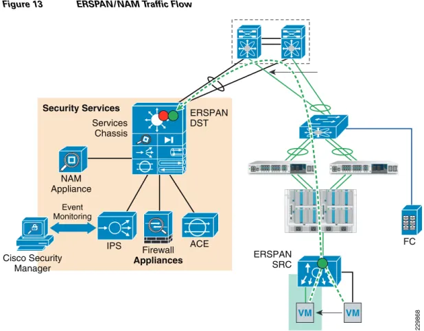
Deploying the Cisco Network Access Module
The Cisco Network Access Module (NAM) provides the capability to terminate Encapsulated Remote Switch Port Analyzer (ERSPAN) sessions and NetFlow connections. The Cisco Nexus 1000V can be configured to initiate ERSPAN sessions to the NAM, where the NAM can be used to capture packets and look at packet statistics. ERSPAN/NAM traffic flow is shown in Figure 13.
Figure 13 ERSPAN/NAM Traffic Flow
To configure ERSPAN between the Nexus 1000V and the services chassis:
1. For ERSPAN, create sessions for different range of VLANs. In this example, five ERSPAN sessions were defined as follows (only two ERSPAN sessions are shown):
monitor session 1 type erspan-source description ** to NAM dc08-namsm-1 ** source vlan 101-110 rx destination ip 10.202.101.200 erspan-id 1 ip ttl 64 ip prec 0 ip dscp 0 mtu 1500 header-type 2
monitor session 50 type erspan-source
description ** INFRA to NAM dc08-namsm-1 ** source vlan 590-600 rx destination ip 10.202.101.200 erspan-id 50 ip ttl 64 ip prec 0 ip dscp 0 mtu 1500 header-type 2
2. The default setting for the ERSPAN sessions is shut to save CPU power on the Cisco Nexus 1000V; you should apply the no shut command on the appropriate ERSPAN session.
drs1-vsm1(config)# monitor session 50 type erspan-source drs1-vsm1(config-erspan-src)# no shut 229868 Services Chassis ERSPAN DST ERSPAN SRC Security Services NAM Appliance Event Monitoring Cisco Security Manager IPS Firewall Appliances ACE FC VM VM
3. The command show monitor session should show the session is operational:
drs1-vsm1# sh monitor
Session State Reason Description
--- --- --- ---1 down Session admin shut ** to NAM dc08-namsm---1 ** 2 down Session admin shut ** to NAM dc07-namsm-1 ** 3 down Session admin shut ** to NAM dc08-namsm-1 ** 4 down Session admin shut ** to NAM dc07-namsm-1 ** 50 up The session is up ** INFRA to NAM dc08-namsm-1 **
The following steps must be configured on the Catalyst 6500 for each ERSPAN session (only sessions 3, 4, and 50 are shown below):
monitor session 50 type erspan-destination
description ** N1k ERSPAN #50 - Tenant 50 INFRA ** destination switch 1 analysis-module 9 data-port 2 source
erspan-id 50
ip address 10.202.101.200
monitor session 3 type erspan-destination description ** N1k ERSPAN #1 - Tenanat 1 ** destination switch 1 analysis-module 9 data-port 1 source
erspan-id 1
ip address 10.202.101.200 !
!
monitor session 4 type erspan-destination description ** N1k ERSPAN #2 - Tenanat 2 ** destination switch 2 analysis-module 9 data-port 1 source
erspan-id 2
ip address 10.202.101.200
Configuring the Cisco Virtual Network Access Module as a NetFlow Collector
The Cisco Virtual Network Access Module (vNAM) is a virtual service blade on the Cisco Nexus 1010 that acts as a NetFlow collector. The traffic flow for the NAM and vNAM is shown in Figure 14.
Figure 14 NAM and vNAM Integration and Traffic Flow
You can use the vNAM as a NetFlow collector by performing the following steps: 1. On the Cisco Nexus 1000, configure the following:
flow exporter vNAM
destination 10.202.101.201 transport udp 3000
source mgmt0 version 9
template data timeout 1800
2. Verify NetFlow is operational by looking at statistics:
drs1-vsm1# show flow exporter
flow monitor NFMonitor record netflow-original exporter namsm-1
exporter vNAM timeout active 1800 cache size 4096
3. Configure NetFlow on all the required port-profiles as shown below:
port-profile type vethernet Management_172_26_162 vmware port-group
vmware max-ports 64 switchport mode access switchport access vlan 162 ip flow monitor NFMonitor input
291445
Aggregation Layer
Nexus 1010
(primary) Nexus 1010(secondary) Po1
Po1 Po78
Po32
Po31 Po101 Po103 Po102 Po104
Domain Service Node NAM UCS Fabric Po45 vNAM VM VM VM N1000v VSM
ip flow monitor NFMonitor output
service-policy type qos input Gold_CoS_6 no shutdown
system vlan 162 state enabled
Flow exporter vNAM:
Destination: 10.202.101.201 VRF: default (1)
Destination UDP Port 3000
Source Interface mgmt0 (172.26.163.109) Export Version 9
Exporter Statistics
Number of Flow Records Exported 50186128 Number of Templates Exported 4313 Number of Export Packets Sent 2239180 Number of Export Bytes Sent 2262224948
The following steps must be performed to configure vNAM:
smt-n1010-1(config)# virtual-service-blade NAM smt-n1010-1(config-vsb-config)# enable primary Enter vsb image: [nam-4-2-1.iso]
Enter Management IPV4 address: 10.202.101.201 Enter Management subnet mask: 255.255.255.0
IPv4 address of the default gateway: 10.202.101.200 Enter HostName: smt-1010-nam
Setting Web user/passwd will enable port 80. Enter[y|n]: [n] y Web User name: [admin]
Web User password: **********
smt-n1010-1(config-vsb-config)# interface data vlan 902
The configuration in the Cisco Nexus 1010 looks like this:
virtual-service-blade NAM
virtual-service-blade-type name NAM-1.0 interface data vlan 902
ramsize 2048 disksize 53
no shutdown secondary
Deploying Cisco Unified Computing System
The basic Cisco UCS configuration can be found in FlexPod for VMware Deployment Model
(http://www.cisco.com/en/US/docs/solutions/Enterprise/Data_Center/Virtualization/flexpod_vmware.h tml). Details of the queuing and bandwidth control configuration used for ESMT are shown in Queuing and Bandwidth Control.
Queuing and Bandwidth Control
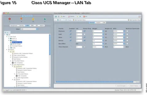
Queuing and bandwidth control are implemented within the Cisco UCS and at the access layer (Cisco Nexus 5000). Within the Cisco UCS, CoS values are assigned to a system class and given a certain percentage of the effective bandwidth. This is configured under the LAN tab in the Cisco UCS Manager (Figure 15).
Figure 15 Cisco UCS Manager—LAN Tab
The settings for the system classes are applied to traffic leaving the Cisco UCS 6100 fabric interconnects toward users and storage.
Deploying NetApp Storage
Deploying NetApp Data ONTAP
Each NetApp controller shares a unified storage architecture based on the Data ONTAP® 7G operating system and uses an integrated suite of application-aware manageability software. This provides an efficient consolidation of storage area network (SAN), network-attached storage (NAS), primary storage, and secondary storage on a single platform while allowing concurrent support for block and file protocols using Ethernet and Fibre Channel interfaces. These interfaces include Fibre Channel over Ethernet (FCoE), Network File System (NFS), Common Internet File System protocol (CIFS), and iSCSI. This common architecture allows businesses to start with an entry-level storage platform and easily migrate to the higher-end platforms as storage requirements increase, without learning a new OS, management tools, or provisioning processes.
To provide resilient system operation and high data availability, Data ONTAP 7G is tightly integrated into the hardware systems. The FAS systems use redundant, hot-swappable components. Combined with the patented dual-parity RAID-DP® (high-performance RAID 6), the net result can be superior data protection with little or no performance loss. For a higher level of data availability, Data ONTAP provides optional mirroring, backup, and disaster recovery solutions.
Active/Active Configuration
A NetApp active/active configuration keeps data available in the unlikely event of a controller failure or when controller maintenance might be necessary. Although this NetApp feature is highlighted in the “FlexPod for VMware Implementation Guide,” it is important to understand some of the rules pertaining to a properly configured active/active controller pair and how the configuration can be tested to enable proper failover if an event should occur.
The Data ONTAP 7.3 Active/Active Configuration Guide details the complete rules and procedures that should be followed to keep the controller configuration consistent with proper active/active controller operation (https://now.netapp.com/NOW/knowledge/docs/ontap/rel7351/pdfs/ontap/aaconfig.pdf). A component of NetApp Data Fabric® Manager (DFM), Operations Manager can be used to check the active/active configuration on both controllers in the high-availability (HA) pair. This tool provides a detailed list of items that are not in compliance with a proper active/active configuration as well as the actions that should be taken to correct such issues.
To run the active/active configuration check tool within Operations Manager: 1. Navigate to the Operations Manager Web GUI.
2. Login as a user with Administrator privileges. 3. Click the Control Center tab.
4. Click the Home tab.
5. Click the Member Details tab.
6. Click the link for either storage controller in the Storage System column.
7. In the menu on the left under Storage Controller Tools, click Check Configuration. Several checks are performed during the active/active configuration check. Potential issues or
configuration errors are presented in list format and appropriate actions should be taken to mitigate these items.
Figure 16 shows an active-active configuration status.
Figure 16 Active/Active Configuration Status
Active/Active Configuration Example
The following example details a proper active/active configuration as it pertains to the implementation of vFiler® units and their associated attributes. Note that other advanced settings are also either required or recommended to be identical on both controllers. The list of advanced settings can be found in the Data ONTAP 7.3 Active/Active Configuration Guide
NetApp1> ifconfig -a
<subsection of output>
vif0: flags=0xa3d0a863<BROADCAST,RUNNING,MULTICAST,TCPCKSUM,VLAN> mtu 9000 ether 02:a0:98:0b:b0:81 (Enabled virtual interface)
vif0-106: flags=0x310a862<BROADCAST,RUNNING,MULTICAST,TCPCKSUM> mtu 9000 partner vif0-106 (not in use)
ether 02:a0:98:0b:b0:82 (Enabled virtual interface)
vif0-109: flags=0x394a863<BROADCAST,RUNNING,MULTICAST,TCPCKSUM> mtu 9000 partner vif0-109 (not in use)
ether 02:a0:98:0b:b0:83 (Enabled virtual interface)
vif0-110: flags=0x310a862<BROADCAST,RUNNING,MULTICAST,TCPCKSUM> mtu 9000 partner vif0-110 (not in use)
ether 02:a0:98:0b:b0:84 (Enabled virtual interface)
vif0-115: flags=0x394a863<BROADCAST,RUNNING,MULTICAST,TCPCKSUM> mtu 9000 partner vif0-115 (not in use)
ether 02:a0:98:0b:b0:85 (Enabled virtual interface)
vif0-119: flags=0x310a862<BROADCAST,RUNNING,MULTICAST,TCPCKSUM> mtu 9000 partner vif0-119 (not in use)
ether 02:a0:98:0b:b0:86 (Enabled virtual interface)
vif0-120: flags=0x310a862<BROADCAST,RUNNING,MULTICAST,TCPCKSUM> mtu 9000 partner vif0-120 (not in use)
ether 02:a0:98:0b:b0:87 (Enabled virtual interface)
vif0-124: flags=0x394a863<UP,BROADCAST,RUNNING,MULTICAST,TCPCKSUM> mtu 9000 inet 10.3.102.100 netmask-or-prefix 0xffffff00 broadcast 10.3.102.255 partner vif0-124 (not in use)
ether 02:a0:98:0b:b0:88 (Enabled virtual interface)
vif0-129: flags=0x394a863<UP,BROADCAST,RUNNING,MULTICAST,TCPCKSUM> mtu 9000
inet 192.168.129.101 netmask-or-prefix 0xffffff00 broadcast 192.168.129.255 partner vif0-129 (not in use)
Table 1 NetApp1 (Physical Controller)
vFiler IPspace VLANs IP Addresses
Infrastructure_vfiler Infrastructure_ipspace 592 599 600 10.50.102.100 192.168.99.101 192.168.100.100 SQL_vfiler SQL_ipspace 124 129 130 10.3.102.100 192.168.129.101 192.168.130.100
Table 2 NetApp2 (Physical Controller)
vFiler IPspace VLANs IP Addresses
Exchange_vfiler Exchange_ipspace 115 119 120 10.2.102.100 192.168.119.101 192.168.120.100 Sharepoint_vfiler Sharepoint_ipspace 106 109 110 10.1.102.100 192.168.109.101 192.168.110.100
ether 02:a0:98:0b:b0:89 (Enabled virtual interface)
vif0-130: flags=0x394a863<UP,BROADCAST,RUNNING,MULTICAST,TCPCKSUM> mtu 9000
inet 192.168.130.100 netmask-or-prefix 0xffffff00 broadcast 192.168.130.255 partner vif0-130 (not in use)
ether 02:a0:98:0b:b0:8a (Enabled virtual interface)
vif0-592: flags=0x394a863<UP,BROADCAST,RUNNING,MULTICAST,TCPCKSUM> mtu 9000 inet 10.50.102.100 netmask-or-prefix 0xffffff00 broadcast 10.50.102.255 partner vif0-592 (not in use)
ether 02:a0:98:0b:b0:8b (Enabled virtual interface)
vif0-599: flags=0x394a863<UP,BROADCAST,RUNNING,MULTICAST,TCPCKSUM> mtu 9000 inet 192.168.99.101 netmask-or-prefix 0xffffff00 broadcast 192.168.99.255 partner vif0-599 (not in use)
ether 02:a0:98:0b:b0:8c (Enabled virtual interface)
vif0-600: flags=0x394a863<UP,BROADCAST,RUNNING,MULTICAST,TCPCKSUM> mtu 9000
inet 192.168.100.100 netmask-or-prefix 0xffffff00 broadcast 192.168.100.255 partner vif0-600 (not in use)
ether 02:a0:98:0b:b0:8d (Enabled virtual interface)
</subsection of output>
NetApp2> ifconfig -a
<subsection of output>
vif0: flags=0xa3d0a863<BROADCAST,RUNNING,MULTICAST,TCPCKSUM,VLAN> mtu 9000 ether 02:a0:98:0b:b0:91 (Enabled virtual interface)
vif0-106: flags=0x310a862<UP,BROADCAST,RUNNING,MULTICAST,TCPCKSUM> mtu 9000 inet 10.1.102.100 netmask-or-prefix 0xffffff00 broadcast 10.1.102.255 partner vif0-106 (not in use)
ether 02:a0:98:0b:b0:92 (Enabled virtual interface)
vif0-109: flags=0x394a863<UP,BROADCAST,RUNNING,MULTICAST,TCPCKSUM> mtu 9000
inet 192.168.109.101 netmask-or-prefix 0xffffff00 broadcast 192.168.109.255 partner vif0-109 (not in use)
ether 02:a0:98:0b:b0:93 (Enabled virtual interface)
vif0-110: flags=0x310a862<UP,BROADCAST,RUNNING,MULTICAST,TCPCKSUM> mtu 9000
inet 192.168.110.100 netmask-or-prefix 0xffffff00 broadcast 192.168.110.255 partner vif0-110 (not in use)
ether 02:a0:98:0b:b0:94 (Enabled virtual interface)
vif0-115: flags=0x394a863<UP,BROADCAST,RUNNING,MULTICAST,TCPCKSUM> mtu 9000 inet 10.2.102.100 netmask-or-prefix 0xffffff00 broadcast 10.2.102.255 partner vif0-115 (not in use)
ether 02:a0:98:0b:b0:95 (Enabled virtual interface)
vif0-119: flags=0x310a862<UP,BROADCAST,RUNNING,MULTICAST,TCPCKSUM> mtu 9000
inet 192.168.119.101 netmask-or-prefix 0xffffff00 broadcast 192.168.119.255 partner vif0-119 (not in use)
ether 02:a0:98:0b:b0:96 (Enabled virtual interface)
vif0-120: flags=0x310a862<UP,BROADCAST,RUNNING,MULTICAST,TCPCKSUM> mtu 9000
inet 192.168.120.100 netmask-or-prefix 0xffffff00 broadcast 192.168.120.255 partner vif0-120 (not in use)
ether 02:a0:98:0b:b0:97 (Enabled virtual interface)
vif0-124: flags=0x394a863<BROADCAST,RUNNING,MULTICAST,TCPCKSUM> mtu 9000 partner vif0-124 (not in use)
ether 02:a0:98:0b:b0:98 (Enabled virtual interface)
vif0-129: flags=0x394a863<BROADCAST,RUNNING,MULTICAST,TCPCKSUM> mtu 9000 partner vif0-129 (not in use)
ether 02:a0:98:0b:b0:99 (Enabled virtual interface)
vif0-130: flags=0x394a863<BROADCAST,RUNNING,MULTICAST,TCPCKSUM> mtu 9000 partner vif0-130 (not in use)
ether 02:a0:98:0b:b0:9a (Enabled virtual interface)
vif0-592: flags=0x394a863<BROADCAST,RUNNING,MULTICAST,TCPCKSUM> mtu 9000 partner vif0-592 (not in use)
ether 02:a0:98:0b:b0:9b (Enabled virtual interface)
partner vif0-599 (not in use)
ether 02:a0:98:0b:b0:9c (Enabled virtual interface)
vif0-600: flags=0x394a863<BROADCAST,RUNNING,MULTICAST,TCPCKSUM> mtu 9000 partner vif0-600 (not in use)
ether 02:a0:98:0b:b0:9d (Enabled virtual interface) </subsection of output>
NetApp1> ipspace list
Number of ipspaces configured: 4
default-ipspace (e0M e0P e0a e0b)
Infrastructure_ipspace (vif0-592 vif0-599 vif0-600) SQL_ipspace (vif0-124 vif0-129 vif0-130) Exchange_ipspace (vif0-115 vif0-119 vif0-120) Sharepoint_ipspace (vif0-106 vif0-109 vif0-110)
NetApp2> ipspace list
Number of ipspaces configured: 4
default-ipspace (e0M e0P e0a e0b)
Infrastructure_ipspace (vif0-592 vif0-599 vif0-600) SQL_ipspace (vif0-124 vif0-129 vif0-130) Exchange_ipspace (vif0-115 vif0-119 vif0-120) Sharepoint_ipspace (vif0-106 vif0-109 vif0-110)
NetApp1> rdfile /etc/rc
<subsection of output>
vif create lacp vif0 -b ip e6a e6b
vlan create vif0 106 110 119 120 124 130 583 589 590 592 600 ifconfig vif0 partner vif0
ifconfig e0a `hostname`-e0a netmask 255.255.0.0 mtusize 1500 mediatype auto flowcontrol full partner e0a
ifconfig vif0-106 `hostname`-vif0-106 netmask 255.255.255.0 mtusize 9000 partner vif0-106 ifconfig vif0-109 `hostname`-vif0-109 netmask 255.255.255.0 mtusize 9000 partner vif0-109 ifconfig vif0-110 `hostname`-vif0-110 netmask 255.255.255.0 mtusize 9000 partner vif0-110 ifconfig vif0-115 `hostname`-vif0-115 netmask 255.255.255.0 mtusize 9000 partner vif0-115 ifconfig vif0-119 `hostname`-vif0-119 netmask 255.255.255.0 mtusize 9000 partner vif0-119 ifconfig vif0-120 `hostname`-vif0-120 netmask 255.255.255.0 mtusize 9000 partner vif0-120 ifconfig vif0-124 `hostname`-vif0-124 netmask 255.255.255.0 mtusize 9000 partner vif0-124 ifconfig vif0-129 `hostname`-vif0-129 netmask 255.255.255.0 mtusize 9000 partner vif0-129 ifconfig vif0-130 `hostname`-vif0-130 netmask 255.255.255.0 mtusize 9000 partner vif0-130 ifconfig vif0-592 `hostname`-vif0-592 netmask 255.255.255.0 mtusize 9000 partner vif0-592 ifconfig vif0-599 `hostname`-vif0-599 netmask 255.255.255.0 mtusize 9000 partner vif0-599 ifconfig vif0-600 `hostname`-vif0-600 netmask 255.255.255.0 mtusize 9000 partner vif0-600
</subsection of output>
NetApp2> rdfile /etc/rc
<subsection of output>
vif create lacp vif0 -b ip e6a e6b
vlan create vif0 106 110 119 120 124 130 583 589 590 592 600 ifconfig vif0 partner vif0
ifconfig e0a `hostname`-e0a netmask 255.255.0.0 mtusize 1500 mediatype auto flowcontrol full partner e0a
ifconfig vif0-109 `hostname`-vif0-109 netmask 255.255.255.0 mtusize 9000 partner vif0-109 ifconfig vif0-110 `hostname`-vif0-110 netmask 255.255.255.0 mtusize 9000 partner vif0-110 ifconfig vif0-115 `hostname`-vif0-115 netmask 255.255.255.0 mtusize 9000 partner vif0-115 ifconfig vif0-119 `hostname`-vif0-119 netmask 255.255.255.0 mtusize 9000 partner vif0-119 ifconfig vif0-120 `hostname`-vif0-120 netmask 255.255.255.0 mtusize 9000 partner vif0-120 ifconfig vif0-124 `hostname`-vif0-124 netmask 255.255.255.0 mtusize 9000 partner vif0-124 ifconfig vif0-129 `hostname`-vif0-129 netmask 255.255.255.0 mtusize 9000 partner vif0-129 ifconfig vif0-130 `hostname`-vif0-130 netmask 255.255.255.0 mtusize 9000 partner vif0-130 ifconfig vif0-592 `hostname`-vif0-592 netmask 255.255.255.0 mtusize 9000 partner vif0-592 ifconfig vif0-599 `hostname`-vif0-599 netmask 255.255.255.0 mtusize 9000 partner vif0-599 ifconfig vif0-600 `hostname`-vif0-600 netmask 255.255.255.0 mtusize 9000 partner vif0-600
</subsection of output>
NetApp1> rdfile /etc/hosts
<subsection of output> 127.0.0.1 localhost # 0.0.0.0 NetApp1-vif0 172.26.162.10 NetApp1 NetApp1-e0a # 0.0.0.0 NetApp1-e0b # 0.0.0.0 NetApp1-e0c # 0.0.0.0 NetApp1-e0d # 0.0.0.0 NetApp1-e0e # 0.0.0.0 NetApp1-e0f 0.0.0.0 NetApp1-vif0-106 10.1.102.100 NetApp2-vif0-106 0.0.0.0 NetApp1-vif0-109 192.168.109.101 NetApp2-vif0-109 0.0.0.0 NetApp1-vif0-110 192.168.110.100 NetApp2-vif0-110 0.0.0.0 NetApp1-vif0-115 10.2.102.100 NetApp2-vif0-115 0.0.0.0 NetApp1-vif0-119 192.168.119.101 NetApp2-vif0-119 0.0.0.0 NetApp1-vif0-120 192.168.120.100 NetApp2-vif0-120 0.0.0.0 NetApp1-vif0-124 0.0.0.0 NetApp2-vif0-124 192.168.129.101 NetApp1-vif0-129 0.0.0.0 NetApp2-vif0-129 192.168.130.100 NetApp1-vif0-130 0.0.0.0 NetApp2-vif0-130 10.50.102.100 NetApp1-vif0-592 0.0.0.0 NetApp2-vif0-592 192.168.99.101 NetApp1-vif0-599 0.0.0.0 NetApp2-vif0-599 192.168.100.100 NetApp1-vif0-600 0.0.0.0 NetApp2-vif0-600 </subsection of output>
NetApp2> rdfile /etc/hosts
<subsection of output> 127.0.0.1 localhost # 0.0.0.0 NetApp2-vif0 172.26.162.11 NetApp2 NetApp2-e0a # 0.0.0.0 NetApp2-e0b # 0.0.0.0 NetApp2-e0c