Corporate Headquarters
Cisco Systems, Inc. 170 West Tasman Drive San Jose, CA 95134-1706 USA
http://www.cisco.com Tel: 408 526-4000
800 553-NETS (6387) Fax: 408 526-4100
Cisco WLAN Controller Web Interface User
Guide
THE SPECIFICATIONS AND INFORMATION REGARDING THE PRODUCTS IN THIS MANUAL ARE SUBJECT TO CHANGE WITHOUT NOTICE. ALL STATEMENTS, INFORMATION, AND RECOMMENDATIONS IN THIS MANUAL ARE BELIEVED TO BE ACCURATE BUT ARE PRESENTED WITHOUT WARRANTY OF ANY KIND, EXPRESS OR IMPLIED. USERS MUST TAKE FULL RESPONSIBILITY FOR THEIR APPLICATION OF ANY PRODUCTS. THE SOFTWARE LICENSE AND LIMITED WARRANTY FOR THE ACCOMPANYING PRODUCT ARE SET FORTH IN THE INFORMATION PACKET THAT SHIPPED WITH THE PRODUCT AND ARE INCORPORATED HEREIN BY THIS REFERENCE. IF YOU ARE UNABLE TO LOCATE THE SOFTWARE LICENSE OR LIMITED WARRANTY, CONTACT YOUR CISCO REPRESENTATIVE FOR A COPY.
The Cisco implementation of TCP header compression is an adaptation of a program developed by the University of California, Berkeley (UCB) as part of UCB’s public domain version of the UNIX operating system. All rights reserved. Copyright © 1981, Regents of the University of California.
NOTWITHSTANDING ANY OTHER WARRANTY HEREIN, ALL DOCUMENT FILES AND SOFTWARE OF THESE SUPPLIERS ARE PROVIDED “AS IS” WITH ALL FAULTS. CISCO AND THE ABOVE-NAMED SUPPLIERS DISCLAIM ALL WARRANTIES, EXPRESSED OR IMPLIED, INCLUDING, WITHOUT
LIMITATION, THOSE OF MERCHANTABILITY, FITNESS FOR A PARTICULAR PURPOSE AND NONINFRINGEMENT OR ARISING FROM A COURSE OF DEALING, USAGE, OR TRADE PRACTICE.
IN NO EVENT SHALL CISCO OR ITS SUPPLIERS BE LIABLE FOR ANY INDIRECT, SPECIAL, CONSEQUENTIAL, OR INCIDENTAL DAMAGES, INCLUDING, WITHOUT LIMITATION, LOST PROFITS OR LOSS OR DAMAGE TO DATA ARISING OUT OF THE USE OR INABILITY TO USE THIS MANUAL, EVEN IF CISCO OR ITS SUPPLIERS HAVE BEEN ADVISED OF THE POSSIBILITY OF SUCH DAMAGES.
Cisco WLAN Controller Web Interface User Guide © 2005 Cisco Systems, Inc. All rights reserved.
CCSP, CCVP, the Cisco Square Bridge logo, Follow Me Browsing, and StackWise are trademarks of Cisco Systems, Inc.; Changing the Way We Work, Live, Play, and Learn, and iQuick Study are service marks of Cisco Systems, Inc.; and Access Registrar, Aironet, ASIST, BPX, Catalyst, CCDA, CCDP, CCIE, CCIP, CCNA, CCNP, Cisco, the Cisco Certified Internetwork Expert logo, Cisco IOS, Cisco Press, Cisco Systems, Cisco Systems Capital, the Cisco Systems logo, Cisco Unity, Empowering the Internet Generation, Enterprise/Solver, EtherChannel, EtherFast, EtherSwitch, Fast Step, FormShare, GigaDrive, GigaStack, HomeLink, Internet Quotient, IOS, IP/TV, iQ Expertise, the iQ logo, iQ Net Readiness Scorecard, LightStream, Linksys, MeetingPlace, MGX, the Networkers logo, Networking Academy, Network Registrar, Packet, PIX, Post-Routing, Pre-Routing, ProConnect, RateMUX, ScriptShare, SlideCast, SMARTnet, StrataView Plus, TeleRouter, The Fastest Way to Increase Your Internet Quotient, and TransPath are registered trademarks of Cisco Systems, Inc. and/or its affiliates in the United States and certain other countries.
All other trademarks mentioned in this document or Website are the property of their respective owners. The use of the word partner does not imply a partnership relationship between Cisco and any other company. (0502R)
C O N T E N T S
Preface
ixAudience
xPurpose
xConventions
xObtaining Documentation
xiCisco.com
xiDocumentation DVD
xiOrdering Documentation
xiiDocumentation Feedback
xiiCisco Product Security Overview
xiiReporting Security Problems in Cisco Products
xiiiObtaining Technical Assistance
xiiiCisco Technical Support Website
xiiiSubmitting a Service Request
xivDefinitions of Service Request Severity
xivObtaining Additional Publications and Information
xivC H A P T E R 1
Using Controller Web User Interface
1-1Web User Interface Areas
1-2Applying Parameters
1-3Refreshing the Screen
1-4Troubleshooting
1-4C H A P T E R 2
Monitor Menu Bar Selection
2-1Summary
2-2Controller Statistics
2-4Ports Statistics
2-6Ports > Statistics
2-7Rogue APs
2-12Rogue AP Detail
2-14Known Rogue APs
2-16Contents
Rogue Clients
2-20Rogue Client Detail
2-21Adhoc Rogues
2-22802.11a Radios
2-23Radio > Statistics
2-24802.11b/g Radios
2-28Clients
2-29Clients > Detail
2-29RADIUS Servers
2-34RADIUS Servers > Authentication Stats
2-34RADIUS Servers > Accounting Stats
2-36C H A P T E R 3
WLANs Menu Bar Selection
3-1WLANs
3-2WLANs > New
3-2WLANs > Edit
3-3WLANs > Mobility Anchors
3-9AP Groups VLAN
3-10C H A P T E R 4
Controller Menu Bar Selection
4-1General
4-2Inventory
4-5Interfaces
4-6Interfaces > New
4-6Interfaces > Edit
4-7Network Routes
4-10Network Routes > New
4-10DHCP Scopes
4-11DHCP Scope > New
4-11DHCP Scope > Edit
4-12Static Mobility Group Members
4-13Mobility Group Member > New
4-13Mobility Group Member > Edit All
4-13Mobility Statistics
4-15Controller Spanning Tree Configuration
4-17Contents
Port > Edit Configuration
4-21Master Controller Configuration
4-24NTP Servers
4-25NTP Servers > New
4-25NTP Servers > Edit
4-26QoS Profiles
4-27Edit QoS Profile
4-28C H A P T E R 5
Wireless Menu Bar Selection
5-1Cisco APs
5-3Cisco APs > Details
5-4802.11a Cisco radio
5-11802.11a Cisco APs > Configure
5-13802.11 AP Interfaces > Performance Profile
5-16802.11a AP Interfaces > Details
5-17802.11b/g Cisco Radios
5-21802.11b/g Cisco Radios > Configure
5-22802.11b/g AP Interfaces > Details
5-25Bridging
5-29Zero Touch Configuration
5-31802.11a Global Parameters
5-32802.11a Global Parameters > Auto RF
5-33802.11b/g Global Parameters
5-37802.11b/g Global Parameters > Auto RF
5-38802.11h
5-42Country
5-43Timers
5-45C H A P T E R 6
Security Menu Bar Selection
6-1RADIUS Authentication Servers
6-3RADIUS Authentication Servers > New
6-4RADIUS Authentication Servers > Edit
6-6RADIUS Accounting Servers
6-8RADIUS Accounting Servers > New
6-9RADIUS Accounting Servers > Edit
6-10Contents
Local Net Users > Edit
6-14MAC Filtering
6-15MAC Filters > New
6-15MAC Filters > Edit
6-16Disabled Clients
6-17Disabled Client > New
6-17Disabled Client > Edit
6-17User Policies
6-18AP Policies
6-19Access Control Lists
6-21Access Control Lists > New
6-21Access Control Lists > Edit
6-21Access Control Lists > Rules > Edit
6-23Access Control Lists > Edit > Add New Rule
6-24Network Access Control
6-26Network Access Control > New
6-26Network Access Control > Edit
6-27NAC Statistics
6-28CA Certification
6-29ID Certificate
6-30ID Certificate > New
6-30Web Authentication Certificate
6-31Trusted AP Policies
6-32Rogue Policy
6-33Standard Signatures
6-34Signature > Detail
6-34Custom Signatures
6-35Client Exclusion Policies
6-36AP Authentication
6-37C H A P T E R 7
Management Menu Bar Selection
7-1Summary
7-2SNMP System Summary
7-3SNMP V3 Users
7-4SNMP V3 Users > New
7-4Contents
SNMP v1/v2c Community > Edit
7-7SNMP Trap Receiver
7-8SNMP Trap Receiver > New
7-8SNMP Trap Receiver > Edit
7-9SNMP Trap Controls
7-10Trap Logs
7-12HTTP Configuration
7-15Telnet-SSH Configuration
7-17Serial Port Configuration
7-18Local Management Users
7-19Local Management Users > New
7-19CLI Sessions
7-20Syslog Configuration
7-21Management Via Wireless
7-22Message Logs
7-23System Resource Information
7-24Controller Crash Information
7-24AP Log Information
7-24Web Login Page
7-25External Web Authentication
7-26C H A P T E R 8
Commands Menu Bar Selection
8-1Download File to Controller
8-2Upload File from Controller
8-3System Reboot
8-4System Reboot > Save?
8-4System Reboot > Confirm
8-4Reset to Factory Default
8-5Set Time
8-6Using the Configuration Wizard
8-7Collect the Initial Configuration Settings
8-7Connect Your Web Browser to a Controller
8-8Configuration Wizard System Information
8-8Service Interface Configuration
8-9Management Interface Configuration
8-9Contents
WLAN Policy Configuration
8-10RADIUS Server Configuration
8-11802.11 Configuration
8-11Configuration Wizard Completed
8-11Preface
Welcome to the Web User Interface Online Help! This help system is designed for use with Cisco WIreless LAN Controllers and comes bundled with the Operating System software.
Note The Web User Interface Online Help pages require that cookies be enabled on your Web Browser. If the Web User Interface fails to appear when you attempt to log on, make sure that cookies are enabled on your Web Browser.
Note The Web User Interface Online Help pages can be blocked by Internet Explorer Content Advisor. If the Web User Interface Online Help pages fail to appear when you click the Help button, make sure Internet Explorer Content Advisor is disabled.
Note The Web User Interface Online Help pages refer to Controllers. The term Controllers generally applies to all Cisco 2000 Series Wireless LAN Controllers, NMWLC6 Controllers, Cisco 4100 Series Wireless LAN Controllers, and Cisco 4400 Series Wireless LAN Controllers unless expressly called out. Similarly, the Web User Interface Online Help pages refer to “access points”. The term access points generally applies to all Cisco Aironet 1000 Series IEEE 802.11a/b/g lightweight access points (Cisco Aironet 1000 Series lightweight access points) and Cisco Aironet 1030 IEEE 802.11a/b/g remote edge lightweight access points (Cisco Aironet 1030 remote edge lightweight access points), unless expressly called out.
This guide consists of the following chapters:
• Chapter 1, “Using Controller Web User Interface,” describes the various sections on the controller user interface.
• Chapter 2, “Monitor Menu Bar Selection,” describes how to monitor the various devices associated with the controller.
• Chapter 3, “WLANs Menu Bar Selection,” explains how to create and configure a WLAN, and implement various features on a WLAN.
• Chapter 4, “Controller Menu Bar Selection,” describes how to configure a controller.
• Chapter 5, “Wireless Menu Bar Selection,” describes how to configure access points, enable bridging feature, and configure global parameters for 802.11a and 802.11b/g networks.
• Chapter 6, “Security Menu Bar Selection,” describes how to implement the various security policies on a controller.
Preface Audience
• Chapter 7, “Management Menu Bar Selection,” describes the various management features that can be implemented on the controller.
• Chapter 8, “Commands Menu Bar Selection,” describes how to download and upload a file through a TFTP server, reboot and reset the controller to factory settings, and so on.
Note If you are configuring the Cisco 4100 Series Wireless LAN Controllers for the very first time, refer to
Using the Configuration Wizard.
Audience
This guide is for the networking professional who installs and manages the Cisco Wireless LAN Controllers using the Web Interface. To use this guide, you should have experience working with the Cisco Wireless LAN Controllers and be familiar with the concepts and terminology of wireless local area networks.
Purpose
This guide provides the information you need to configure Wireless LAN Controllers and the access points associated with the controller.
Conventions
This publication uses these conventions to convey instructions and information: Command descriptions use these conventions:
• Commands and keywords are in boldface text.
• Arguments for which you supply values are in italic.
• Square brackets ([ ]) mean optional elements.
• Braces ({ }) group required choices, and vertical bars ( | ) separate the alternative elements.
• Braces and vertical bars within square brackets ([{ | }]) mean a required choice within an optional element.
Interactive examples use these conventions:
• Terminal sessions and system displays are in screen font.
• Information you enter is in boldface screen font.
• Nonprinting characters, such as passwords or tabs, are in angle brackets (< >). Notes, cautions, and timesavers use these conventions and symbols:
Tip Means the following will help you solve a problem. The tips information might not be troubleshooting or even an action, but could be useful information.
Preface
Obtaining Documentation
Note Means reader take note. Notes contain helpful suggestions or references to materials not contained in this manual.
Caution Means reader be careful. In this situation, you might do something that could result equipment damage or loss of data.
Warning This warning symbol means danger. You are in a situation that could cause bodily injury. Before you work on any equipment, be aware of the hazards involved with electrical circuitry and be familiar with standard practices for preventing accidents.
Obtaining Documentation
Cisco documentation and additional literature are available on Cisco.com. Cisco also provides several ways to obtain technical assistance and other technical resources. These sections explain how to obtain technical information from Cisco Systems.
Cisco.com
You can access the most current Cisco documentation at this URL:
http://www.cisco.com/univercd/home/home.htm
You can access the Cisco website at this URL:
http://www.cisco.com
You can access international Cisco websites at this URL:
http://www.cisco.com/public/countries_languages.shtml
Documentation DVD
Cisco documentation and additional literature are available in a Documentation DVD package, which may have shipped with your product. The Documentation DVD is updated regularly and may be more current than printed documentation. The Documentation DVD package is available as a single unit. Registered Cisco.com users (Cisco direct customers) can order a Cisco Documentation DVD (product number DOC-DOCDVD=) from the Ordering tool or Cisco Marketplace.
Cisco Ordering tool:
http://www.cisco.com/en/US/partner/ordering/
Cisco Marketplace:
Preface Obtaining Documentation
Ordering Documentation
You can find instructions for ordering documentation at this URL:
http://www.cisco.com/univercd/cc/td/doc/es_inpck/pdi.htm
You can order Cisco documentation in these ways:
• Registered Cisco.com users (Cisco direct customers) can order Cisco product documentation from the Ordering tool:
http://www.cisco.com/en/US/partner/ordering/
• Nonregistered Cisco.com users can order documentation through a local account representative by calling Cisco Systems Corporate Headquarters (California, USA) at 408 526-7208 or, elsewhere in North America, by calling 1 800 553-NETS (6387).
Documentation Feedback
You can send comments about technical documentation to [email protected].
You can submit comments by using the response card (if present) behind the front cover of your document or by writing to the following address:
Cisco Systems
Attn: Customer Document Ordering 170 West Tasman Drive
San Jose, CA 95134-9883 We appreciate your comments.
Cisco Product Security Overview
Cisco provides a free online Security Vulnerability Policy portal at this URL:
http://www.cisco.com/en/US/products/products_security_vulnerability_policy.html
From this site, you can perform these tasks:
• Report security vulnerabilities in Cisco products.
• Obtain assistance with security incidents that involve Cisco products.
• Register to receive security information from Cisco.
A current list of security advisories and notices for Cisco products is available at this URL:
http://www.cisco.com/go/psirt
If you prefer to see advisories and notices as they are updated in real time, you can access a Product Security Incident Response Team Really Simple Syndication (PSIRT RSS) feed from this URL:
Preface
Obtaining Technical Assistance
Reporting Security Problems in Cisco Products
Cisco is committed to delivering secure products. We test our products internally before we release them, and we strive to correct all vulnerabilities quickly. If you think that you might have identified a vulnerability in a Cisco product, contact PSIRT:
• Emergencies —[email protected]
• Nonemergencies —[email protected]
Tip We encourage you to use Pretty Good Privacy (PGP) or a compatible product to encrypt any sensitive information that you send to Cisco. PSIRT can work from encrypted information that is compatible with PGP versions 2.x through 8.x.
Never use a revoked or an expired encryption key. The correct public key to use in your correspondence with PSIRT is the one that has the most recent creation date in this public key server list:
http://pgp.mit.edu:11371/pks/lookup?search=psirt%40cisco.com&op=index&exact=on
In an emergency, you can also reach PSIRT by telephone:
• 1 877 228-7302
• 1 408 525-6532
Obtaining Technical Assistance
For all customers, partners, resellers, and distributors who hold valid Cisco service contracts, Cisco Technical Support provides 24-hour-a-day, award-winning technical assistance. The Cisco Technical Support Website on Cisco.com features extensive online support resources. In addition, Cisco Technical Assistance Center (TAC) engineers provide telephone support. If you do not hold a valid Cisco service contract, contact your reseller.
Cisco Technical Support Website
The Cisco Technical Support Website provides online documents and tools for troubleshooting and resolving technical issues with Cisco products and technologies. The website is available 24 hours a day, 365 days a year, at this URL:
http://www.cisco.com/techsupport
Access to all tools on the Cisco Technical Support Website requires a Cisco.com user ID and password. If you have a valid service contract but do not have a user ID or password, you can register at this URL:
http://tools.cisco.com/RPF/register/register.do
Note Use the Cisco Product Identification (CPI) tool to locate your product serial number before submitting a web or phone request for service. You can access the CPI tool from the Cisco Technical Support Website by clicking the Tools & Resources link under Documentation & Tools. Choose Cisco Product Identification Tool from the Alphabetical Index drop-down list, or click the Cisco Product Identification Tool link under Alerts & RMAs. The CPI tool offers three search options: by product ID or model name; by tree view; or for
Preface Obtaining Additional Publications and Information
certain products, by copying and pasting show command output. Search results show an illustration of your product with the serial number label location highlighted. Locate the serial number label on your product and record the information before placing a service call.
Submitting a Service Request
Using the online TAC Service Request Tool is the fastest way to open S3 and S4 service requests. (S3 and S4 service requests are those in which your network is minimally impaired or for which you require product information.) After you describe your situation, the TAC Service Request Tool provides recommended solutions. If your issue is not resolved using the recommended resources, your service request is assigned to a Cisco TAC engineer. The TAC Service Request Tool is located at this URL:
http://www.cisco.com/techsupport/servicerequest
For S1 or S2 service requests or if you do not have Internet access, contact the Cisco TAC by telephone. (S1 or S2 service requests are those in which your production network is down or severely degraded.) Cisco TAC engineers are assigned immediately to S1 and S2 service requests to help keep your business operations running smoothly.
To open a service request by telephone, use one of the following numbers: Asia-Pacific: +61 2 8446 7411 (Australia: 1 800 805 227)
EMEA: +32 2 704 55 55 USA: 1 800 553-2447
For a complete list of Cisco TAC contacts, go to this URL:
http://www.cisco.com/techsupport/contacts
Definitions of Service Request Severity
To ensure that all service requests are reported in a standard format, Cisco has established severity definitions.
• Severity 1 (S1)—Your network is “down,” or there is a critical impact to your business operations. You and Cisco will commit all necessary resources around the clock to resolve the situation.
• Severity 2 (S2)—Operation of an existing network is severely degraded, or significant aspects of your business operation are negatively affected by inadequate performance of Cisco products. You and Cisco will commit full-time resources during normal business hours to resolve the situation.
• Severity 3 (S3)—Operational performance of your network is impaired, but most business operations remain functional. You and Cisco will commit resources during normal business hours to restore service to satisfactory levels.
• Severity 4 (S4)—You require information or assistance with Cisco product capabilities, installation, or configuration. There is little or no effect on your business operations.
Obtaining Additional Publications and Information
Information about Cisco products, technologies, and network solutions is available from various online and printed sources.
Preface
Obtaining Additional Publications and Information
http://www.cisco.com/go/marketplace/
• Cisco Press publishes a wide range of general networking, training and certification titles. Both new and experienced users will benefit from these publications.
For current Cisco Press titles and other information, go to Cisco Press at this URL:
http://www.ciscopress.com
• Packet magazine is the Cisco Systems technical user magazine for maximizing Internet and networking investments. Each quarter, Packet delivers coverage of the latest industry trends, technology breakthroughs, and Cisco products and solutions, as well as network deployment and troubleshooting tips, configuration examples, customer case studies, certification and training information, and links to scores of in-depth online resources. You can access Packet magazine at this URL:
http://www.cisco.com/packet
• iQ Magazine is the quarterly publication from Cisco Systems designed to help growing companies learn how they can use technology to increase revenue, streamline their business, and expand services. The publication identifies the challenges facing these companies and the technologies to help solve them, using real-world case studies and business strategies to help readers make sound technology investment decisions. You can access iQ Magazine at this URL:
http://www.cisco.com/go/iqmagazine
• Internet Protocol Journal is a quarterly journal published by Cisco Systems for engineering professionals involved in designing, developing, and operating public and private internets and intranets. You can access the Internet Protocol Journal at this URL:
http://www.cisco.com/ipj
• World-class networking training is available from Cisco. You can view current offerings at this URL:
Preface Obtaining Additional Publications and Information
C H A P T E R
1
Using Controller Web User Interface
The Web User Interface is built into each Cisco Wireless LAN Controller. The Web User Interface allows up to five users to simultaneously browse into the built-in controller http or https (http + SSL) Web server, configure parameters, and monitor operational status for the controller and its associated access points.
Because the Web User Interface works with one controller at a time, the Web User Interface is especially useful when you wish to configure or monitor a single controller and its associated access points.
Note Cisco strongly recommends that you enable the https: and disable the http:interfaces to ensure more robust security for your Cisco WLAN Solution. For information on disabling http: interface, refer to
HTTP Configuration.
Note Some popup window filters can be configured to block the Web User Online Help windows. If your system cannot display the Online Help windows, disable or reconfigure your browser popup filter software.
A typical Web User Interface page consists of five areas. The following figure illustrates them.
Chapter 1 Using Controller Web User Interface Web User Interface Areas
Refer to the following for more information:
• Applying Parameters
• Refreshing the Screen
• Troubleshooting
Web User Interface Areas
The following sections describe the Web User Interface page areas and how to use them:
• Menu Bar
• Selector Area
• Main Data Page
• Administrative Tools
• Button Area
Menu Bar
The menu bar shows the names of the main configuration areas of the controller. Refer to the following for available menu bar selections:
• Monitor Menu Bar Selection
• WLANs Menu Bar Selection
• Controller Menu Bar Selection
• Wireless Menu Bar Selection
• Security Menu Bar Selection
• Management Menu Bar Selection
• Commands Menu Bar Selection
Selector Area
The selector area allows you to select a new configuration panel under the menu area that you have selected. You may select a single choice from several available for data to be displayed or configured. The selector area options vary based on the menu you select.
Main Data Page
The main data page depends on what information the menu requires. Input fields are of two basic types:
• Text Fields into which data may be entered using the keyboard.
• Pull-downs from which one of several options may be chosen.
Input fields are black text on a white background. When you enter or select data, it does not go to the controller, but is saved in the field until you click the Apply button. There may be fields that contain buttons. Selecting a button does take immediate effect. Data may also be displayed.
Chapter 1 Using Controller Web User Interface
Web User Interface Areas
Note Microsoft Internet Explorer generates a submit action on the next available button when you press the enter key while in an input field. On most menus this triggers the apply function.
Administrative Tools
This area provides shortcuts to administration functions used on a regular basis when configuring a controller through the Web User Interface.
• Save Configuration: Data is saved to the controller in non-volatile RAM (NVRAM) and is preserved in the event of a power cycle. If you reboot the controller, all applied changes are lost unless the configuration has been saved. Click on the Save button to save the current configuration.
• Ping: Send a Ping to a network element.
This pop-up window allows the you to tell the controller to send a Ping request to a specified IP address. This can help you determine if there is connectivity between the controller and a particular IP station. Once the operator clicks the Submit button, three pings are sent and the results of the ping are displayed in the pop-up. If a reply to the ping is not received, it shows No Reply Received from IP xxx.xxx.xxx.xxx, otherwise it shows Reply received from IP xxx.xxx.xxx.xxx: (send count = 3, receive count = n).
• Logout: Exit the current Web User Interface session.
Button Area
At the right side of the main data area are command buttons to apply or refresh the data displayed in the main data area or request a help window.
Buttons take immediate effect when you select them and information goes to the controller about the state of the menu at that time. The most commonly used buttons are:
• Apply: Data is sent to the controller and made to take effect, but not preserved across a power cycle; these parameters are stored temporarily in volatile RAM.
• New: Select to add a new item to a list.
• Refresh: Update the data on the current screen from the controller.
• Help: Request that the help page be displayed in a new browser window.
There are additional buttons to perform other actions and not all main data areas have all buttons. The functionality of these buttons are described under the respective help topics.
Applying Parameters
After submitting the new parameters or settings entered the page is refreshed. However, in some cases, the settings may appear different than specified by the operator. This happens where timers are involved and the affected code takes some period of time to execute. Refreshing the menu or tree shows the expected results. An example of this occurs when you enable the spanning tree mode or disabled on the controller.
Chapter 1 Using Controller Web User Interface Web User Interface Areas
Refreshing the Screen
Using the refresh function from the Web User Interface refreshes all screens and displays the default initial screen in the main data area.
If you want to refresh a screen in the main data area, and there is no refresh button present on that screen, use your mouse to right-click on the main data area screen, then select the refresh option.
Troubleshooting
Some popup window filters can be configured to block the Web User Interface Online Help windows. If your system does not display the Online Help windows, disable or reconfigure your browser popup filter software.
C H A P T E R
2
Monitor Menu Bar Selection
This menu bar selection provides access to the controller and access points’ summary details. Use the selector area to access the respective network details. Making this selection from the menu bar displays the system Summary page.
The following sections can be accessed from this menu bar:
• Summary
• Controller Statistics
• Ports Statistics
• Ports > Statistics
• Rogue APs
• Rogue AP Detail
• Known Rogue APs
• Known Rogue APs > New
• Rogue AP Detail
• Rogue Clients
• Rogue Client Detail
• Adhoc Rogues
• 802.11a Radios
• Radio > Statistics
• 802.11b/g Radios
• Clients
• Clients > Detail
• RADIUS Servers
• RADIUS Servers > Authentication Stats
Chapter 2 Monitor Menu Bar Selection Summary
Summary
Use MONITOR > Summary to navigate to this page.
The summary page provides a top level description of your controller, access points, clients, WLANs, and rogues. Rogues are unauthorized devices (access points, clients) which are connected to your network.
The controller image is displayed at the top of the summary page and gives information about the controller model number and the number of access points supported by the controller.
The following table describes the parameters on this page. This page is refreshed every 30 seconds.
Note All parameters on this page are read-only parameters.
Table 2-1 Summary Parameters Parameter Description Controller Summary
Management IP Address Management IP address of the controller.
Service Port IP Address The IP address of the controller front-panel service port. Software Version The version of the Operating System running on the controller. System Name Controller name specified by the operator.
Up Time Time elapsed since the controller was last rebooted. System Time Current time set on the controller.
Internal Temperature Current internal chassis temperature. 802.11a Network State Enabled or disabled.
802.11b/g Network State Enabled or disabled.
Access Point Summary
802.11a Radios Number of 802.11a Cisco radios. Click Detail for additional information about 802.11a Radios.
802.11b/g Radios Number of 802.11b/g Cisco radios. Click Detail for additional information about 802.11b/g Radios.
All APs Number of access points associated with this controller. Click Detail
for additional information about Cisco APs.
Client Summary
Current Clients Number of clients currently associated with the controller. Click
Detail for additional information about current Clients.
Excluded Clients Enable or disable automatic excluding for client computers by MAC address.
Disabled Clients Number of clients that are currently disabled.
Rogue Summary
Chapter 2 Monitor Menu Bar Selection
Summary
Active Rogue Clients Active clients associated with a rogue access point. Click Detail for additional information about Rogue Client Detail.
Adhoc Rogues Click Detail for additional information about Adhoc Rogues.
Top WLANs
WLAN Name of the WLAN as specified by the operator.
# of Clients by SSID Number of clients associated with the WLAN based on SSID.
Table 2-1 Summary Parameters (continued) Parameter Description
Chapter 2 Monitor Menu Bar Selection Controller Statistics
Controller Statistics
Use MONITOR > Statistics > Controller to navigate to this page.
The following table describes the controller statistics displayed on this page.
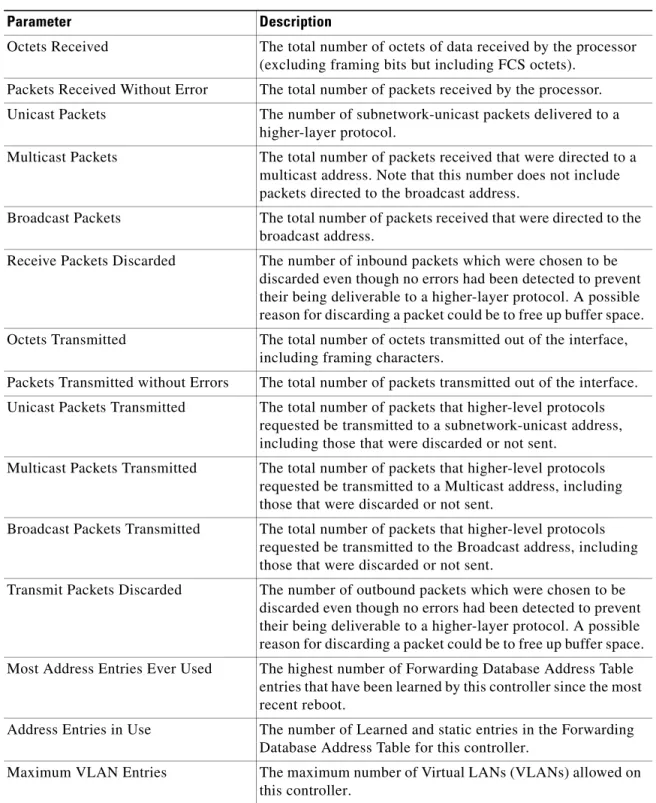
Table 2-2 Controller Summary Statistics Parameter Description
Octets Received The total number of octets of data received by the processor (excluding framing bits but including FCS octets).
Packets Received Without Error The total number of packets received by the processor. Unicast Packets The number of subnetwork-unicast packets delivered to a
higher-layer protocol.
Multicast Packets The total number of packets received that were directed to a multicast address. Note that this number does not include packets directed to the broadcast address.
Broadcast Packets The total number of packets received that were directed to the broadcast address.
Receive Packets Discarded The number of inbound packets which were chosen to be discarded even though no errors had been detected to prevent their being deliverable to a higher-layer protocol. A possible reason for discarding a packet could be to free up buffer space. Octets Transmitted The total number of octets transmitted out of the interface,
including framing characters.
Packets Transmitted without Errors The total number of packets transmitted out of the interface. Unicast Packets Transmitted The total number of packets that higher-level protocols
requested be transmitted to a subnetwork-unicast address, including those that were discarded or not sent.
Multicast Packets Transmitted The total number of packets that higher-level protocols requested be transmitted to a Multicast address, including those that were discarded or not sent.
Broadcast Packets Transmitted The total number of packets that higher-level protocols requested be transmitted to the Broadcast address, including those that were discarded or not sent.
Transmit Packets Discarded The number of outbound packets which were chosen to be discarded even though no errors had been detected to prevent their being deliverable to a higher-layer protocol. A possible reason for discarding a packet could be to free up buffer space. Most Address Entries Ever Used The highest number of Forwarding Database Address Table
entries that have been learned by this controller since the most recent reboot.
Address Entries in Use The number of Learned and static entries in the Forwarding Database Address Table for this controller.
Maximum VLAN Entries The maximum number of Virtual LANs (VLANs) allowed on this controller.
Chapter 2 Monitor Menu Bar Selection
Controller Statistics
Command Buttons
• Clear Counters: Sets all summary and detailed controller statistics counters to zero; also resets the “Time Since Counters Last Cleared” field.
• Help: Request that the help page be displayed in a new browser window.
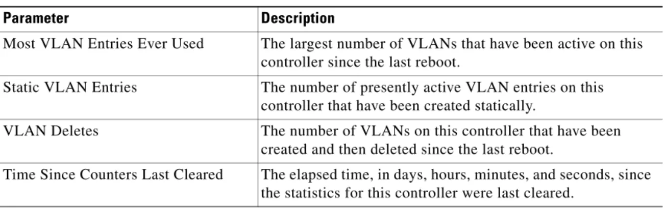
Most VLAN Entries Ever Used The largest number of VLANs that have been active on this controller since the last reboot.
Static VLAN Entries The number of presently active VLAN entries on this controller that have been created statically.
VLAN Deletes The number of VLANs on this controller that have been created and then deleted since the last reboot.
Time Since Counters Last Cleared The elapsed time, in days, hours, minutes, and seconds, since the statistics for this controller were last cleared.
Table 2-2 Controller Summary Statistics (continued) Parameter Description
Chapter 2 Monitor Menu Bar Selection Ports Statistics
Ports Statistics
Use MONITOR > Statistics > Ports to navigate to this page.
This page displays the status of each port on the controller. The following table provides a description and the range for each parameter.
The Physical Mode and Status may reflect different values depending on the link status. For example, the Physical Mode may be set to “Auto” while the link actually runs at “10 Mbps Half Duplex”. Select the View Stats link to see detailed statistics for each port on Ports > Statistics.
Command Buttons
• Help: Request that the help page be displayed in a new browser window.
Table 2-3 Summary Parameters
Parameter Description Range
Port No Port number on the controller. 1-12 for 10/100Base-T, 13 for 1000Base-T or -SX . 1-24 for 10/100Base-T, 25 for 1000Base-T or -SX . 1 for 1000Base-SX on a Cisco 4100 Series Wireless LAN Controller.
1 for 1000Base-SX on a Cisco 4100 Series Wireless LAN Controller.
Admin Status State of the port. Enable; Disable. Physical Mode Displays the configuration of
the port physical interface.
Auto.
100 Mbps Full Duplex. 100 Mbps Half Duplex. 10 Mbps Full Duplex. 10 Mbps Half Duplex. 1000 Mbps Full Duplex.
Note In a Cisco NMWLC6 controller, the physical mode is always set to “Auto”. Physical Status Displays the actual port
physical interface.
Auto.
100 Mbps Full Duplex. 100 Mbps Half Duplex. 10 Mbps Full Duplex. 10 Mbps Half Duplex. 1000 Mbps Full Duplex. Link Status Displays the status of the link. Link Up; Link Down.
Chapter 2 Monitor Menu Bar Selection
Ports Statistics
Ports > Statistics
Use MONITOR > Statistics > Ports and then click View Stats to navigate to this page.
This page displays statistics on a per port basis. The Port Number appears on the main data page directly below the page title and above the Traffic Statistics tables. The following tables explain the port statistics.
Table 2-4 Traffic Statistics
Parameter Received Description Transmitted Description
Total Bytes The total number of octets of data (including those in bad packets) received on the network (excluding framing bits but including FCS octets). This object can be used as a reasonable estimate of Ethernet utilization. If greater precision is desired, the etherStatsPkts and etherStatsOctets objects should be sampled before and after a common interval. The result of this equation is the value Utilization which is the percent utilization of the Ethernet segment on a scale of 0 to 100 percent.
The total number of octets of data (including those in bad packets) received on the network (excluding framing bits but including FCS octets). This object can be used as a reasonable estimate of Ethernet utilization. If greater precision is desired, the etherStatsPkts and etherStatsOctets objects should be sampled before and after a common interval.
Packets (64 Octets)
The total number of packets (including bad packets) received that were 64 octets in length (excluding framing bits but including FCS octets).
The total number of packets
(including bad packets) received that were 64 octets in length (excluding framing bits but including FCS octets).
Packets
(65-127 Octets)
The total number of packets (including bad packets) received that were between 65 and 127 octets in length inclusive (excluding framing bits but including FCS octets).
The total number of packets
(including bad packets) received that were between 65 and 127 octets in length inclusive (excluding framing bits but including FCS octets). Packets
(128-255 Octets)
The total number of packets (including bad packets) received that were between 128 and 255 octets in length inclusive (excluding framing bits but including FCS octets).
The total number of packets
(including bad packets) received that were between 128 and 255 octets in length inclusive (excluding framing bits but including FCS octets). Packets
(256-511 Octets)
The total number of packets (including bad packets) received that were between 256 and 511 octets in length inclusive (excluding framing bits but including FCS octets).
The total number of packets
(including bad packets) received that were between 256 and 511 octets in length inclusive (excluding framing bits but including FCS octets). Packets
(512-1023 Octets)
The total number of packets (including bad packets) received that were between 512 and 1023 octets in length inclusive (excluding framing bits but including FCS octets).
The total number of packets
(including bad packets) received that were between 512 and 1023 octets in length inclusive (excluding framing bits but including FCS octets).
Chapter 2 Monitor Menu Bar Selection Ports Statistics
Maximum Info size allowed - The maximum size of the Info (non-MAC) field that this port receives or transmits.
Packets
(1024-1518 Octets)
The total number of packets (including bad packets) received that were between 1024 and 1518 octets in length inclusive (excluding framing bits but including FCS octets).
The total number of packets
(including bad packets) received that were between 1024 and 1518 octets in length inclusive (excluding framing bits but including FCS octets).
Packets (1519-1530 Octets)
The total number of packets (including bad packets) received that were between 1519 and 1530 octets in length inclusive (excluding framing bits but including FCS octets).
The total number of packets
(including bad packets) received that were between 1519 and 1530 octets in length inclusive (excluding framing bits but including FCS octets).
Packets
(> 1530 Octets)
The total number of packets received that were longer than 1530 octets (excluding framing bits, but including FCS octets) and were otherwise well formed.
The total number of packets transmitted that were longer than 1530 octets (excluding framing bits, but including FCS octets) and were otherwise well formed.
Table 2-4 Traffic Statistics (continued)
Parameter Received Description Transmitted Description
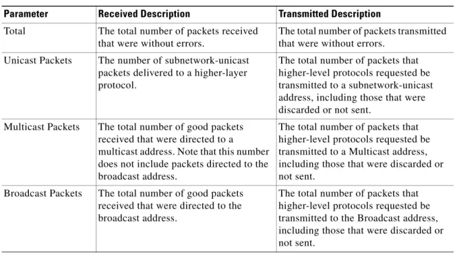
Table 2-5 Successful Packets
Parameter Received Description Transmitted Description
Total The total number of packets received that were without errors.
The total number of packets transmitted that were without errors.
Unicast Packets The number of subnetwork-unicast packets delivered to a higher-layer protocol.
The total number of packets that higher-level protocols requested be transmitted to a subnetwork-unicast address, including those that were discarded or not sent.
Multicast Packets The total number of good packets received that were directed to a
multicast address. Note that this number does not include packets directed to the broadcast address.
The total number of packets that higher-level protocols requested be transmitted to a Multicast address, including those that were discarded or not sent.
Broadcast Packets The total number of good packets received that were directed to the broadcast address.
The total number of packets that higher-level protocols requested be transmitted to the Broadcast address, including those that were discarded or not sent.
Chapter 2 Monitor Menu Bar Selection
Ports Statistics
Time Since Counters Last Cleared: The elapsed time, in days, hours, minutes, and seconds since the statistics for this port were last cleared.
Click Clear Counters to set all summary and controller detailed statistics counters to zero; also resets the “Time Since Counters Last Cleared” field.
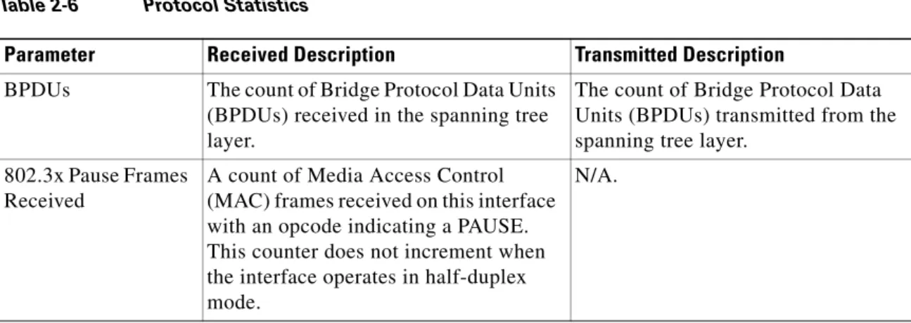
Table 2-6 Protocol Statistics
Parameter Received Description Transmitted Description
BPDUs The count of Bridge Protocol Data Units (BPDUs) received in the spanning tree layer.
The count of Bridge Protocol Data Units (BPDUs) transmitted from the spanning tree layer.
802.3x Pause Frames Received
A count of Media Access Control (MAC) frames received on this interface with an opcode indicating a PAUSE. This counter does not increment when the interface operates in half-duplex mode.
N/A.
Table 2-7 Received Packets with MAC Errors Parameter Description
Total The total number of inbound packets that contained errors preventing them from being deliverable to a higher-layer protocol.
Jabbers The total number of packets received that were longer than 1518 octets (excluding framing bits, but including FCS octets), and had either a bad Frame Check Sequence (FCS) with an integral number of octets (FCS Error) or a bad FCS with a non-integral number of octets (Alignment Error). Note that this definition of jabber differs from the definition in IEEE-802.3 section 8.2.1.5 (10Base-5) and section 10.3.1.4 (10Base-2). These documents define jabber as the condition where any packet exceeds 20 ms. The allowed range to detect jabber is between 20 ms and 150 ms.
Fragments/Undersiz e
The total number of packets received that were less than 64 octets in length (excluding framing bits but including FCS octets).
Alignment Errors The total number of packets received that had a length (excluding framing bits, but including FCS octets) of between 64 and 1518 octets, inclusive, but had a bad Frame Check Sequence (FCS) with a non-integral number of octets. FCS Errors The total number of packets received that had a length (excluding framing bits,
but including FCS octets) of between 64 and 1518 octets, inclusive, but had a bad Frame Check Sequence (FCS) with an integral number of octets.
Overruns The total number of frames discarded as this port was overloaded with incoming packets, and could not keep up with the inflow.
Chapter 2 Monitor Menu Bar Selection Ports Statistics
Table 2-8 Received Packets Not Forwarded Parameter Description
Total A count of valid frames received which were discarded, or filtered, by the forwarding process.
Local Traffic Frames The total number of frames dropped in the forwarding process because the destination address was located off of this port. 802.3x Pause Frames Received A count of MAC Control frames received on this interface with an
opcode indicating the PAUSE operation. This counter does not increment when the interface operates in half-duplex mode. Unacceptable Frame Type The number of frames discarded from this port due to being an
unacceptable frame type.
VLAN Membership Mismatch The number of frames discarded on this port due to ingress filtering. VLAN Viable Discards The number of frames discarded on this port when a lookup on a
particular VLAN occurs while that entry in the VLAN table is being modified, or if the VLAN has not been configured.
Multicast Tree Viable Discards The number of frames discarded when a lookup in the multicast tree for a VLAN occurs while that tree is being modified.
Reserved Address Discards The number of frames discarded that are destined to an IEEE 802.1 reserved address and are not supported by the system.
CFI Discards The number of frames discarded that have CFI bit set and the addresses in RIF are in non-canonical format.
Upstream Threshold The number of frames discarded due to lack of cell descriptors available for that packet's priority level.
Table 2-9 Transmit Errors
Parameter Description
Total Errors The sum of Single, Multiple, and Excessive Collisions.
FCS Errors The total number of packets transmitted that had a length (excluding framing bits, but including FCS octets) of between 64 and 1518 octets, inclusive, but had a bad Frame Check Sequence (FCS) with an integral number of octets.
Oversized The total number of frames that exceeded the maximum permitted frame size. This counter has a maximum increment rate of 815 counts per second at 10 Mbps.
Underrun Errors The total number of frames discarded because the transmit FIFO buffer became empty during frame transmission.
Chapter 2 Monitor Menu Bar Selection
Ports Statistics
Command Buttons
• Back: Return to the previous window.
• Help: Request that the help page be displayed in a new browser window.
Table 2-10 Transmit Discards
Parameter Description
Total Discards The sum of single collision frames discarded, multiple collision frames discarded, and excessive frames discarded.
Single Collision Frames A count of the number of successfully transmitted frames on a particular interface for which transmission is inhibited by exactly one collision.
Excessive Collisions A count of frames for which transmission on a particular interface fails due to excessive collisions.
Port Membership The number of frames discarded on egress for this port due to egress filtering being enabled.
VLAN Viable Discards The number of frames discarded on this port when a lookup on a particular VLAN occurs while that entry in the VLAN table is being modified, or when the VLAN has not been configured. Multiple Collision Frames A count of the number of successfully transmitted frames on a
particular interface for which transmission is inhibited by more than one collision.
Chapter 2 Monitor Menu Bar Selection Rogue APs
Rogue APs
Use MONITOR > Summary > Rogue Summary > Active Rogue APs > Detail or MONITOR > Wireless > Rogue APs or WIRELESS > Rogue APs to navigate to this page.
This page displays access points in your air space which are not part of your configured network. These rogue access point radios may be one of the following four types:
• Pending or Alert radio: This type of radio may present a threat to the integrity and security of your network. It has not been identified as a Known internal radio or as an Acknowledged radio belonging to another company located near your premises.
• Known radio: This radio has been identified and accepted as being secure. This radio is being used for accepted company functions, but is not part of the internal network.
• Acknowledged radio: This radio is transmitting from a known source outside of the company network. This radio may be part of another company’s LAN which is located on another floor or in close proximity to your network. This radio does not present a security threat to your network.
• Contained radio: Between one and four access points are transmitting de-authorization and disassociate messages to clients attempting to associate with the rogue access point.
The following information is provided when a rogue access point radio is detected:
This page reports rogue access points until the “Expiration Timeout for Rogue AP Entries” (set on the
Rogue Policy page) expires.
The Edit links in the rogue access point radios table take you to the respective Rogue AP Detail page when selected.
Table 2-11 Rogue Access Point Radios Parameter Description
MAC Address Media Access Control address of the rogue access point.
SSID Service Set Identifier being broadcast by the rogue access point radio. # Detecting Radios Number of Cisco radios detecting the rogue access point radio. Number of Clients Number of clients currently associated with the rogue access point. Status Automatic and configurable state of this radio relative to the network or
controller. The status of rogue access point radios appear as one of the following:
• Pending - OS identification is still underway.
• Alert - first scanned by the controller, and maintained in this state until the user changes the state.
• Known - known internal access point being used for accepted company functions, but it is not part of the internal network.
• Acknowledge - this radio is transmiting from an external source outside of the company network.
• Contained - between one and four access points are transmitting deauthorization and disassociate messages to clients attempting to associate with this rogue access point.
Chapter 2 Monitor Menu Bar Selection
Rogue APs
Command Buttons
• Next: Displays the next page of the listing.
• Help: Request that the help page be displayed in a new browser window.
Rogue AP Detail
Use MONITOR > Summary > Rogue Summary > Active Rogue APs > Detail and then click Edit to navigate to this page.
This page displays the access point details of the unauthorized or unknown radio. The following information is provided when a rogue access point radio is detected:
Table 2-12 Rogue Access Point Radio Details Parameter Description
MAC Address Media Access Control address of the rogue access point. Type Rogue access point type:
AP = Infrastructure access point Ad Hoc = Client-to-Client Is Rogue on Wired
Network?
Yes or No. Unknown if WEP is enabled, as shown lower on this page. First Time Reported On Date and time the radio was first scanned by the controller.
Last Time Reported On Date and time the radio was last scanned by the controller. Current Status The status of this radio is:
• Alert (Unknown access point)
• Known (Internal access point)
• Acknowledge (External access point)
• Contain (Rogue access point)
• Pending (unidentified)
Update Status (Note) Configurable state of this rogue access point in the controller. You may set the status to:
• Contain Rogue - Discourage all rogue access point clients, and then choose the number of Cisco access points (1 through 4) that should be used to contain the rogue.
• Alert Unknown rogue access point
• Known Internal rogue access point.
Note When you update the status of a rogue access point to Known Internal and click Apply, that rogue access point gets listed on
Known Rogue APs page.
• Acknowledge external rogue access point
Note Make sure you do not attempt to contain rogue access points operated by other establishments, such as the cafe hotspot across the street!
Chapter 2 Monitor Menu Bar Selection Rogue APs
Cisco APs that Detected this Rogue
This table provides a detailed list of access points that detect the unauthorized radio as well as the transmit characteristics of the radio. The following information physically identifies the location of the rogue access point.
• MAC address of the Cisco access point that identified the rogue access point radio.
• Name of the Cisco access point that identified the rogue access point radio.
• SSID - Service Set Identifier being broadcast by the rogue access point radio.
• Channel - Which channel the rogue access point is broadcasting on.
• Radio Type - Protocol of the rogue access point is either 802.11a, 802.11b or 802.11g.
• WEP - Whether WEP is enabled or disabled.
• WPA - This type of security protocol is Enabled or Disabled.
• Pre-Amble - Whether the Preamble is Short or Long.
• RSSI (receive signal strength indicator) of rogue access point radio at the access point (-80 dBm or lower, the rogue access point is far away or transmitting at a low signal strength; -60 dBm or higher, the rogue access point is close and/or transmitting at a high signal strength).
• SNR (signal to noise ratio) of rogue access point radio at the access point.
• Containment Type - ‘Contained’ if the rogue access point clients have been contained at Level 1 through Level 4 under Update Status Maximum Number, otherwise blank.
• Containment Channels - Current channel or channels if the rogue access point clients have been contained at Level 1 through Level 4 under Update Status, otherwise blank.
Clients associated to this Rogue AP
This table provides a detailed list of clients associated to this rogue access point.
• MAC address - Media Access Control of the Rogue Client.
• Last Time Heard - The last time the Cisco access point detected the rogue access point client.
Command Buttons
• Back: Return to the previous window.
• Apply: Data is sent to the controller and made to take effect, but not preserved across a power cycle; these parameters are stored temporarily in volatile RAM.
Chapter 2 Monitor Menu Bar Selection
Rogue APs
Known Rogue APs
Use MONITOR > Wireless > Known Rogue APs or WIRELESS > Rogues > Known Rogue APs to navigate to this page.
This page displays details about Known Rogue APs that have been configured on the network.
From the summary table, select Edit to bring up the Known Rogue AP Detail page where you can view the details and also update the status of the Known Rogue access point.
Select Remove from the summary table to remove the selected Known Rogue access point. You are prompted to confirm the removal.
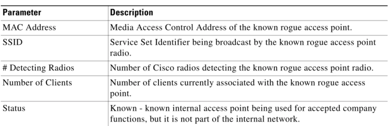
Table 2-13 Known Rogue Access Points Parameter Description
MAC Address Media Access Control Address of the known rogue access point. SSID Service Set Identifier being broadcast by the known rogue access point
radio.
# Detecting Radios Number of Cisco radios detecting the known rogue access point radio. Number of Clients Number of clients currently associated with the known rogue access
point.
Status Known - known internal access point being used for accepted company functions, but it is not part of the internal network.
Chapter 2 Monitor Menu Bar Selection Known Rogue APs > New
Known Rogue APs > New
Use MONITOR > Wireless > Known Rogue APs or Wireless > Rogues > Known Rogue APs and then click New to navigate to this page. This page allows you to add an access point to the Known Rogue APs list.
To add an access point, perform these steps:
Step 1 Enter the MAC address of the access point in the MAC Address field.
Step 2 Click Apply button to bring up the Known Rogue APs page where the access point that you added is displayed.
Known Rogue AP Detail
Use MONITOR > Wireless > Known Rogue APs or Wireless > Rogues > Known Rogue APs and then click Edit to navigate to this page.
This page displays the details of the authorized or known rogue access point. The following information is provided:
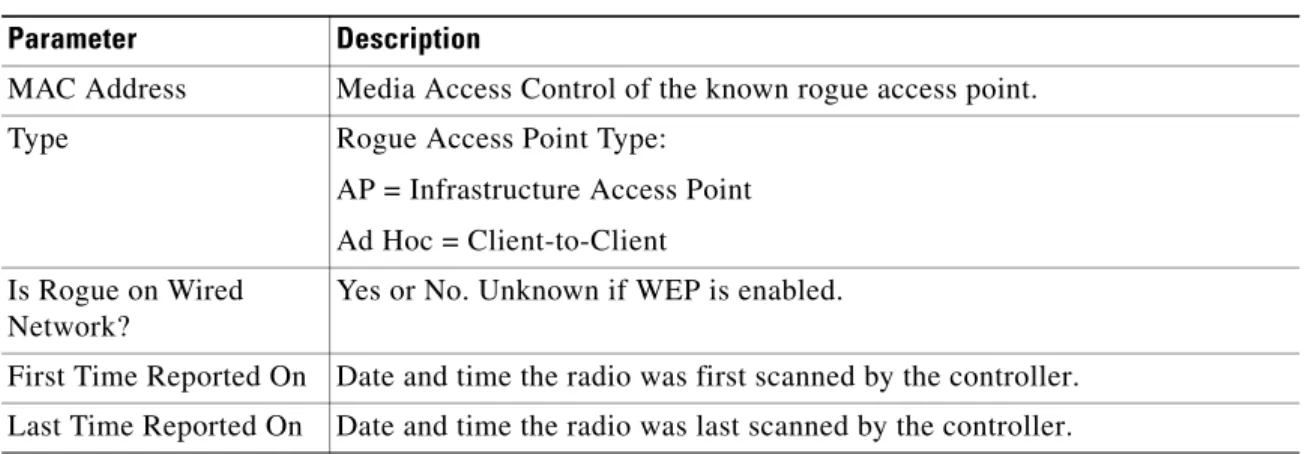
Table 2-14 Known Rogue AP Detail Parameter Description
MAC Address Media Access Control of the known rogue access point. Type Rogue Access Point Type:
AP = Infrastructure Access Point Ad Hoc = Client-to-Client Is Rogue on Wired
Network?
Yes or No. Unknown if WEP is enabled.
First Time Reported On Date and time the radio was first scanned by the controller. Last Time Reported On Date and time the radio was last scanned by the controller.
Chapter 2 Monitor Menu Bar Selection
Known Rogue APs > New
Cisco APs that Detected this Rogue
This table provides a detailed list of the access points that detect the authorized radio as well as the transmit characteristics of the radio. The following information physically identifies the location of the known rogue access point.
• The MAC address of the access point that identified the known rogue access point radio.
• Name of the access point that identified the known rogue access point radio.
• SSID - Service Set Identifier being broadcast by the known rogue access point radio.
• Channel - Which channel the known rogue access point is broadcasting on.
• Radio Type - Protocol of the known rogue access point is either 802.11a, 802.11b or 802.11g.
• WEP - Whether WEP is enabled or disabled.
• WPA - This type of security protocol is Enabled or Disabled.
• Pre-Amble - Whether the Preamble is Short or Long.
• RSSI (receive signal strength indicator) of known rogue access point radio at the access point (-80 dBm or lower, the rogue access point is far away or transmitting at a low signal strength; -60 dBm or higher, the rogue access point is close and/or transmitting at a high signal strength).
• SNR (signal to noise ratio) of the known rogue access point radio at the Cisco access point.
• Containment Type - ‘Contained’ if the rogue access point clients have been contained at Level 1 through Level 4 under Update Status Maximum Number, otherwise blank.
• Containment Channels - Current channel or channels if the rogue access point clients have been contained at Level 1 through Level 4 under Update Status, otherwise blank.
Current Status The status of this radio is:
• Alert (Unknown access point)
• Known (Internal access point)
• Acknowledge (External access point)
• Contain (Rogue access point)
• Pending (unidentified)
Update Status (Note) Configurable state of this known rogue access point in the controller. You may set the status to:
• Contain Rogue - Discourage all rogue access point clients, and then choose the number of access points (1 through 4) to contain the rogue.
• Alert Unknown rogue access point
• Known Internal rogue access point
• Acknowledge External rogue access point
Table 2-14 Known Rogue AP Detail (continued) Parameter Description
Chapter 2 Monitor Menu Bar Selection Known Rogue APs > New
Clients associated to this Known Rogue AP
This table provides a detailed list of clients associated to this known rogue access point.
• MAC address - Media Access Control of the known rogue client.
• Last Time Heard - The last time the Cisco access point detected the known rogue access point client.
Command Buttons
• Back: Return to the previous window.
• Apply: Data is sent to the controller and made to take effect, but not preserved across a power cycle; these parameters are stored temporarily in volatile RAM.
Chapter 2 Monitor Menu Bar Selection
Rogue Clients
Rogue Clients
Use MONITOR > Wireless > Rogue Clients or MONITOR > Summary > Rogue Clients to navigate to this page.
This page contains information about detected rogue clients.
The Edit link in the rogue clients table takes you to Rogue Client Detail when selected.
Command Button
• Help: Request that the help page be displayed in a new browser window.
Table 2-15 Rogue Clients
Parameters Description
MAC Address MAC address of the rogue client. AP MAC Address MAC address of the Cisco access point.
SSID Service Set Identifier being broadcast by the rogue client. # Detecting Radios Number of Cisco radios detecting the rogue client.
Last Seen On The last time the Cisco access point detected the rogue access point client.
Status Configurable state of this radio relative to the network or controller. Rogue radios appear as “Alert” when first scanned by the controller, or as “Pending” when OS identification is still underway.