Sharif University of Technology
Scientia IranicaTransactions B: Mechanical Engineering www.scientiairanica.com
Research Note
Application of the ball-spine algorithm to design an
axial-ow compressor blade
A. Madadi
a, M.J. Kermani
a;and M. Nili-Ahmadabadi
ba. Department of Mechanical Engineering, Amirkabir University of Technology, Tehran, P.O. Box 15875-4413, Iran. b. Department of Mechanical Engineering, Isfahan University of Technology, Isfahan, P.O. Box 84156-83111, Iran. Received 22 October 2012; received in revised form 26 December 2013; accepted 26 February 2014
KEYWORDS Ball-spine algorithm; Inverse design; Compressor blade prole;
Target pressure distribution; Computed pressure distribution.
Abstract. In this paper, a novel inverse design algorithm, called a ball spine algorithm, is developed to design the blade to blade ow passage of axial-ow compressors. The algorithm considers the blade surfaces as a set of virtual balls that move freely along the specied directions, called `spines'. To start the solution, an initial guess for the blade geometry is required. Then, the blade-to-blade ow eld is solved using an in-house inviscid solver. Comparing the Computed Pressure Distribution (CPD) with the Target Pressure Distribution (TPD) over the blade surfaces gives guidelines in dierential movements for the balls to obtain a modied geometry. For the modied geometry, new grids are automatically generated by an algebraic-elliptic grid-generator. The sequence is repeated until the target pressure is met. An error parameter, PD, indicating the dierence between CPD and TPD along the suction and pressure surfaces, is computed, while the blade geometry evolves toward the target geometry. For the initial guess, PD is obtained as 13700 Pa, while, after 100 generations, PD is reduced to 222 Pa.
© 2014 Sharif University of Technology. All rights reserved.
1. Introduction
The design of hardware involving uid ow or heat transfer, such as intakes, manifolds, compressors and turbine blades, etc., is dened as the shape deter-mination of solid elements, so that the ow or heat transfer rate is optimized in some senses. Often, both Computational Fluid Dynamics (CFD) and design algorithms are involved in determining an optimal shape. The computational costs in design techniques are usually a challenge, so, an appropriate algorithm for rapid shape determination is always of interest to designers in the eld.
*. Corresponding author. Tel.: +98 21 64543421; Fax: +98 21 66419736
E-mail addresses: [email protected] (A. Madadi); [email protected] (M.J. Kermani); [email protected] (M. Nili-Ahmadabadi)
In general, the design problems are categorized in two groups; optimization and inverse design. In optimization problems, an objective function, which could be a compound of various targets, is dened, and, using optimization algorithms, the optimum values for the design parameters are determined. Li et al. [1] de-veloped a blading design optimization system using an aeromechanical approach and harmonic perturbation method. They implemented this method on a NASA 67 rotor and improved the eciency of the rotor by 0.4% considering stress limitations. Verstraete et al. [2] presented a multidisciplinary optimization and applied it to the design of a small radial compressor impeller. In this method, a genetic algorithm and articial neural network have been used to nd geometry with maxi-mum eciency, regarding a maximaxi-mum stress limitation in the blades.
The other type of design problem is Surface Shape Design (SSD). Surface Shape Design (SSD) in uid ow
problems usually involves nding a shape associated with a prescribed distribution of surface pressure or velocity. It should be noted that the solution of an SSD problem is not generally an optimum solution in a mathematical sense. It just means that the solution satises a Target Pressure Distribution which resembles a nearly optimum performance [3].
There are basically two dierent algorithms for solving SSD problems: decoupled (iterative) and pled (direct or non-iterative) techniques. In the cou-pled solution approach, an alternative formulation of the problem is used in which the surface coordinates appear (explicitly or implicitly) as dependent variables. In other words, the coupled methods tend to nd the unknown part of the boundary values and the ow eld unknowns simultaneously in a (theoretically) single-pass or one-shot approach [4]. The governing equations of coupled methods are more complicated than the well-known uid dynamics equations; hence, these methods are limited to simple ow regimes. In addition, conventional ow eld solvers could not be used.
The iterative shape design approach relies on repeated shape modications, such that each iteration consists of a ow eld solution followed by a geometry generation scheme. In other words, a series of sequen-tial problems are solved in which the surface shape is modied (evolved) in each geometry generation so that the desired TPD is eventually achieved [5]. In iterative methods, the governing equations are similar to ow eld equations and conventional solvers could be used as a black-box. Hence, iterative methods are applicable for complicated ow regimes.
Iterative methods, such as optimization tech-niques, have been, by far, the most widely used in solv-ing practical SSD problems. The traditional iterative methods used for SSD problems are often based on trial and error or optimization-search algorithms. The trial and error search process is very time-consuming and computationally expensive, and, hence, needs designer experience to reduce computation costs. Optimization methods [6,7] are commonly used to automate the new generation of geometry in each iteration cycle. In such methods, an objective function (e.g., the dierence between the computed surface pressure and the target surface pressure, PD [8]) is minimized, subject to ow constraints which have to be satised. Although the iterative methods are general and powerful, they are often computationally costly and mathematically complex [9]. These methods can utilize the method of ow eld analysis as a black-box.
Other iterative methods presented so far use phys-ical instead of mathematphys-ical algorithms to automate the geometry modication in each iteration cycle. The physical-based methods are easier and quicker than the mathematical (or optimization based) iterative
methods. One of these physical algorithms is governed by a transpiration model in which one can assume that the wall is porous. Hence, the mass can be ctitiously injected through the wall in such a way that the new wall satises the no ow through the wall boundary condition [10]. This method is aimed to remove nonzero normal velocity on the boundary. A geometry update is determined by applying either the transpiration model based on mass ux conservation [11-15] or the streamline model based on alignments [16]. An alter-native algorithm is based on the residual-correction approach. In this method, the key problem is to relate the computed dierence between actual pressure distribution on the current estimate of the geometry and the TPD (the residual) to the required changes in the geometry. In this method, the art in the development of a residual-correction method is to nd an optimum state between the computational eort (for determining the required geometry correction) and the number of iterations needed to obtain a converged solution. This geometry correction may be estimated by means of a simple correction role, making use of relations between geometry changes and pressure dierences known from linearized ow theory. The residual-correction decoupled solution methods try to utilize the analysis methods as a black-box.
Barger and Brooks [17] presented a streamline curvature method in which they considered the pos-sibility of relating a local change in surface curvature to a change in local velocity. Since then, a large number of methods have been developed following that concept [18-26].
Nili et al. presented an iterative inverse design method for internal ows called the Flexible String Algorithm (FSA). They considered the duct wall as a exible string, frequently deformed under the dif-ference between TPD and CPD, PD = TPD CPD. They developed this method for non-viscous compress-ible [27,28] and viscous incompresscompress-ible internal ow regimes [29].
Recently, Nili et al. presented a novel inverse design method called the Ball-Spine algorithm (BS algorithm). They developed this method for quasi-3D design of the meridional plane of centrifugal compres-sors [30].
In this paper, the BS algorithm is implemented for the design of a Double Circular Arc (DCA) prole. To do so, corrected geometry for both suction and pressure surfaces have been consecutively generated until the target pressure distributions on both surfaces are achieved. For the ow eld solution, a recently developed in-house code, based on the Roe scheme, is used. After each geometry evolution step, the domain grids have been regenerated using an in-house algebraic-elliptic grid generation code. As an initial guess for the geometry, a straight duct (at plate
airfoil) has been used, which gives the error parameter, PD = 13700 Pa, where PD is the average absolute value of the dierence between computed and target pressure distributions, i.e. CPD and TPD, along the blade surfaces. After 100 geometry corrections (evolvement) PD is reduced to 222 Pa. To ensure the uniqueness of the solution, the procedure is repeated using a dierent initial guess for the geometry, and it is observed that the solution has converged to the same target geometry. To present the eectiveness of the design algorithm, two design problems have also been performed. First, a pressure distribution with a higher loading has been considered as the target pressure distribution, and the corresponding airfoil-shape has been determined. Then, a target pressure distribu-tion with a lower adverse pressure gradient on the suction surface has been used, and the corresponding geometry which satises the target pressure has been obtained. The design method has also been applied to a transonic test case and the method is shown to be reliable. As a sensitivity analysis, the eect of the geometry correction coecient, C, on the stability and convergence rate of the method has also been studied and an optimum value for this coecient is obtained.
2. The Ball-Spine (BS) algorithm
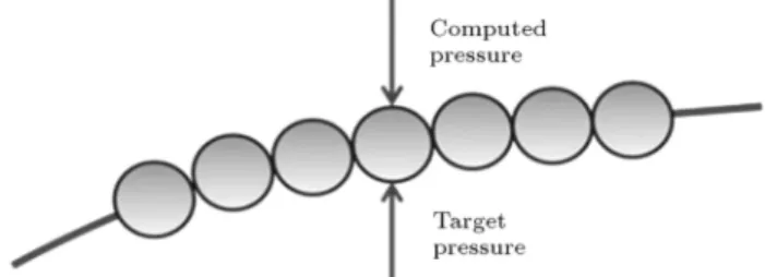
In the present work, the ball-spine algorithm is applied to the design of a 2D airfoil. At rst, the basis of the ball-spine algorithm is detailed. To do so, a two dimensional internal ow through a duct is considered as an example. Here, a target pressure distribution (or prole) along the duct is specied, and the corresponding geometry is determined through the BS algorithm. To start the solution, an initial guess for the duct cross sectional prole is required to be made. Here, the duct walls are considered as a set of virtual balls (see Figure 1) that are only allowed to freely move along specied directions called spines. For the guessed duct prole (or the duct geometry that does not yet correspond to the target pressure), ow motion through the duct applies a pressure to the wall of the duct, here called computed pressure. For a uid tube
Figure 1. Simulation of a 2-D duct with balls and spine directions.
(or say a control volume around the uid), this pressure is applied at the outer side of the wall, as shown in Figure 2. This pressure, in general, is dierent from the required target pressure. Hence, the exible wall (i.e. the balls) is assumed to deform in such a way as to reach a shape satisfying the target pressure. That is, the force due to the dierence between the target and computed pressure at each point on the wall is applied to each virtual ball and causes them to move. As the target shape is obtained, this pressure dierence vanishes and the balls will stop moving.
To derive the kinematic relations of a exible wall, a uniform mass distribution along the wall is assumed. The free body diagram of the ball is shown in Figure 3. The net force applied to the ball along the spine direction is computed as:
FSp= P:A: cos ; (1)
where the subscript Sp indicates the spine direction and:
P = PTarget PComp.; (2)
and A is the projected area of each element and is the angle between the force vector and spine direction. If a ball moves along the spine direction through a specied time step (t), the corresponding displacement is
Figure 2. Applying the target and computed pressures on a sample ball.
Figure 3. Free body diagram of a sample ball on the duct wall.
computed from the following dynamic relations:
s = 12a(t)2; a =FSp
m ; (3)
where m and s are the mass and displacement of the virtual ball, respectively. Substituting Eqs. (1) and (2) into Eq. (3) yields:
s = 1 2
A
m(t)2(PTarget PComp.) cos ; (4) or:
s = C:P: cos ; P = (PTarget PComp.) ; (5)
where C = A:(t)2=2m is a constant called the
\Geom-etry Correction Coecient", with a typical value within the range of 0.0001-0.0005 (m2.s2/kg). Considering
a large value for parameter C causes the balls dis-placements to increase and the convergence rate to be improved. On the other hand, if parameter C exceeds a limit, the solution becomes unstable. Although a small value of C causes the design procedure to be stable, the convergence rate decreases. Hence, an optimum value for the geometry correction coecient, which depends on pressure gradients, ow regimes, geometry etc., is usually determined by a trial and error process.
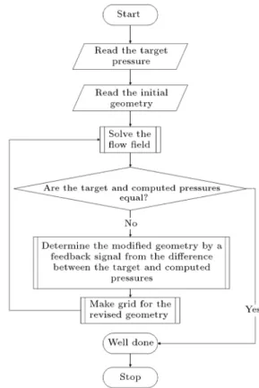
Based on the value of for each ball (or better to say, for each computational node along the wall), the new geometry is determined. Then, grids for the revised geometry are generated, and the ow eld is solved using a ow solver. The procedure is continued until the computed pressure matches the target pressure. The owchart of the design algorithm is shown in Figure 4. Because, in the ow eld solver, back pressure is imposed at the outlet (which is xed), and the rst point on the walls must be xed, the target and computed surface pressures are gauged relative to the leading edge pressure, i.e:
Prel = P PLE: (6)
For the geometry correction, the relative pressure, Prel,
is used in Eq. (5).
It should be noted that for supersonic ows, the change of pressure with change of area diers from the subsonic ow regime. Hence, Eq. (5) is rewritten as:
(
s = C:P: cos if Mach < 1
s = C:P: cos if Mach > 1 (7) 2.1. The modied wall geometry
Here, the spine directions are selected along the vertical lines, i.e. with the same x-coordinates as illustrated earlier in Figure 1. In other words, the x-coordinates of the balls on the top and bottom walls of Figure 1
Figure 4. The design owchart.
remain the same through the shape modication proce-dure. The modied wall geometry, i.e. the new position of each ball, is calculated as follows:
xnew = xold; (8)
and:
ynew= yold+ s: (9)
2.2. The wall smoothness
In this process, a wall is considered as a set of separated balls. During the design/modication procedure, the curvature of this wall may result in discontinuous shapes in adjacent nodes (balls), as shown in Figure 5. To smooth out the curvature of the wall, a ltration scheme is applied. This process is performed after each geometry correction step. The ltration scheme is formulated as follows:
y(i; j) = y(i 1; j) + f:y(i; j) + y(i + 1; j)f + 2 : (10) Here, f is the ltration coecient. Large values for f correspond to a low degree of ltration and small values for f result in a greater degree of ltration. In the present work, f is set to 4, i.e:
y(i; j) = y(i 1; j) + 4y(i; j) + y(i + 1; j)
6 : (11)
In Figure 5, the ltered geometry is plotted using a dashed line. A higher order of ltration decreases the convergence rate, but improves the stability of the design method.
Figure 5. Wall boundary before and after ltration.
2.3. The compressor blades design procedure In the design procedure of compressor blades, a target pressure distribution is usually provided for each airfoil surface, i.e. for the suction and pressure sides. To enforce the target pressure distributions along the suction and pressure surfaces, geometry correction is done by applying pressure distributions alternatively to the suction and pressure surfaces, in such a way that only one boundary is corrected at each step and the other is kept xed. Finally, when both pressure distributions match, the geometry is determined. 2.4. Inviscid/viscous design procedures
The ball-spine algorithm can incorporate either an in-house code or a commercial ow solver for the iterative procedure of shape determination. As the ow solver is like a black-box to the BS algorithm, either inviscid or viscous ow solvers can be adopted.
The prescribed BS algorithm uses pressure distri-bution for geometry correction, by which, the separat-ing regions within the ow elds, usually appearseparat-ing in regions of large adverse pressure gradients, are avoided. Hence, the trends of pressure distribution determination for inviscid and viscous ows over the surfaces are similar. As a result, rst, a designer can use an inviscid ow solver to obtain a primary solution quickly. Then, using a viscous ow solver, the accuracy of the solution can be either checked or improved. If the designed geometry, obtained by the inviscid solver, provides a mild enough adverse pressure gradient, then, the occurrence of separating regions by the viscous ow solver can be checked.
3. Flow eld solution
The governing equations for two-dimensional, com-pressible, unsteady, inviscid ow in the conservative form are given as follows:
@Q @t +
@E @x +
@G
@y = 0; (12)
where: Q = 2 6 6 4 u v et 3 7 7 5 ; E =
2 6 6 4
u u2+ P
uv uht
3 7 7 5 ; G =
2 6 6 4 v uv v2+ P
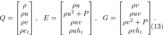
vht 3 7 7 5 : (13) Here, Q is the conservative vector, and E and G are the inviscid ux vectors. The equations are written in the generalized form using metrics of transformation, as: @Q @t + @E @x + @G
@y = 0; (14)
where: Q1=QJ;
E1=J1(xE + yG) ;
G1=J1 (xE + yG) : (15)
Eq. (3) is discretized as follows: @Q1
@t +
E1E E1W
+
G1N G1S
= 0; (16) where E1E is the inviscid numerical ux computed in
generalized coordinates at the east cell face, E. E1W,
G1N and G1S are the ux vectors at west, north and
south faces, respectively. To solve the inviscid ow eld, a recently developed in-house code, based on the Flux Dierence Splitting (FDS) scheme of Roe [31], is used. The governing equations are discretized using formulations presented by Kermani [32]. The inviscid numerical ux, E1E, is written in generalized
coordinates, according to Ref. [32], as:
E1E= 12(E1L+ E1R) 12 4
X
m=1
jmj WmTm; (17)
where E1Land E1Rare the inner and outer value of E1
at face E, is the eigenvalue of the Jacobian matrix determined under Roe averaged conditions, W is the wave amplitude, and T is the eigenvector corresponding to the eigenvalue, . For a complete description of these parameters, the reader is referred to [31,32].
The Roe scheme gives non-physical expansion shocks in the regions where the eigenvalues of the Jacobian matrix vanish, e.g. the sonic regions and stagnation points. To avoid expansion shocks in the regions where the eigenvalues vanish, an entropy correction formula from Kermani and Plett is used here [33]. To validate the solver, the numerical results are compared with the experimental data of Emery et al. for a 2-dimensional NACA65-410 cascade [34]. In Figure 6, the pressure coecient on the blade surfaces is plotted and compared with experimental data for a cascade with a solidity of 1.0, stagger angle of 22.5,
Figure 6. Comparison between numerical results and experimental data for 2-D NACA65-410 cascade.
Figure 7. A sample of grid generated by an in-house grid-generator code.
3.1. Grid generation
A combined algebraic-elliptic algorithm is used for grid generation [35]. To impose grid orthogonality on the blade surfaces and clustering near the wall, the corresponding control functions are considered in the elliptic algorithm. An example of a generated grid for a blade cascade is shown in Figure 7.
3.2. Boundary conditions
For compressible ow in a compressor blade cascade, the pressure inlet and pressure outlet boundary condi-tions are applied at inlet and outlet boundaries, respec-tively. Two periodic boundaries are considered before and after the blade. The slip boundary conditions are applied to the blade suction and pressure surfaces.
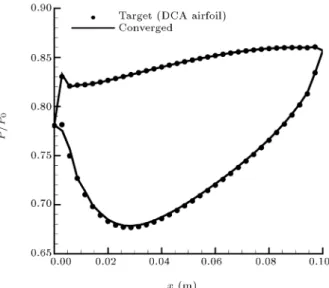
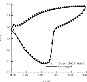
Figure 8. Pressure distributions for the target and the converged geometries for the Double Circular Arc (DCA) blade.
4. Results and discussion
The BS algorithm is applied to a Double Circular Arc (DCA) blade to assess the applicability of this method. In this computation, the back pressure ratio is set to PBack=P0 = 0:843. This guarantees
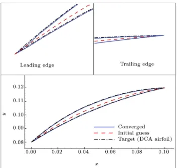
a subsonic ow over the suction and pressure sides of the DCA blade. The blade cascade is shown in Figure 7. To validate the method, the ow eld around the DCA airfoil is solved, and pressure distribution on the suction and pressure surfaces of the airfoil is obtained. These pressure distributions are considered as target pressure distributions, as the rst assessment of the BS-algorithm. Starting from a at plate airfoil (straight line) as an initial guess for the geometry, the geometry modication (also called the design process) is continued until the target pressure distribution is reached. It is noted in this rst study that the airfoil geometry corresponding to the prescribed loading is the DCA blade. As shown in Figure 8, target and nal (converged) pressure distributions present very good agreement. The initial, target and converged geometries are shown in Figure 9. Also shown in this gure are magnications of viewpoints near the leading and trailing edges for better comparison. To assess the uniqueness of the method, the procedure is repeated using a dierent initial guess for geometry. That is an airfoil of zero thickness, as shown in Figure 10, which is used as an initial guess for the geometry. This gure shows that for the given target pressure distribution of Figure 8, the BS design algorithm produces the same DCA airfoil geometry as illustrated in Figure 9. In short, it is said that, for a given target pressure distribution, as shown in Figure 8, the nal converged geometry using two dierent initial guesses for the geometries (i.e. a at-plate airfoil as shown in Figure 9,
P D =
iPTE
i=iLE
(PTarget PComp.)iSuction surface+ i=iPTE
i=iLE
(PTarget PComp.)iPressure surface
2 (iTE iLE+ 1) : (18)
Box I
Figure 9. The evolution of the blade geometry for the rst assessment of the BS algorithm: Staring from a at-plate airfoil as the initial guess, it is shown that the nal converged geometry matches very well with the DCA airfoil.
Figure 10. Assessment of the BS-algorithm: Staring from a dierent initial guess for the DCA airfoil (dierent from the at-plate airfoil as noted in Figure 9), it is shown that the BS design algorithm nds the same DCA airfoil geometry.
Figure 11. Eect of geometry correction coecient, C, on convergence rate of the design process; curve of PD with geometry generation number (here PD represents the dierence between the computed and target pressure distributions).
and a zero thickness airfoil as shown in Figure 10) produce the same results.
To assess the convergence degree of the solution, an error parameter, called PD, is also dened in Eq. (18) as shown in Box I.
In Figure 11, the convergence history of the design process is shown for dierent values of geometry correction coecient, C. The convergence rate is increased as coecient C is increased to an optimum value of 0.00030 m2.s2/kg. More increase in values of
C results in divergence of the method. It is concluded that for a design process, an optimum or critical value of geometry correction coecient, C, should be determined.
To assess the accuracy of the BS algorithm for transonic ow regimes, the back pressure for the DCA blade ow-eld shown in Figure 7 is decreased to PBack=P0 = 0:759. With reduced back pressure
value, the ow in the passage becomes transonic and Mach number increases in the domain. The method is applied, considering the mentioned pressure dis-tribution, using a at plate airfoil (straight line) as the initial guessed geometry. Comparison between target and converged pressure distributions is shown in Figure 12. Also Mach number distribution is presented
Figure 12. Target and converged pressure distributions for transonic test case.
Figure 13. Mach number distribution for the target and the converged geometries for transonic test case.
in Figures 13 and 14. A shock is observed on the suction surface of the blade.
The previous test cases were studied for validation of the ball-spine algorithm. Here, as an applied exam-ple, a new target pressure distribution is considered and the accuracy and applicability of the method is assessed. To do this, using the pressure distributions of the DCA airfoil, the target pressure distribution is suggested to have higher loading. In Figure 15, the original, target (with higher loading) and converged pressure distributions are compared. The area between blade surface pressure distributions corresponds to blade loading, which is increased in this test case. In Figure 16, the original and new designed airfoil that has a greater loading is illustrated.
Figure 14. Cascade ow eld shown by Mach number contours for the transonic test case.
Figure 15. Original, increased loading and converged pressure distributions.
Figure 16. Original and new designed airfoils for increased loading test case.
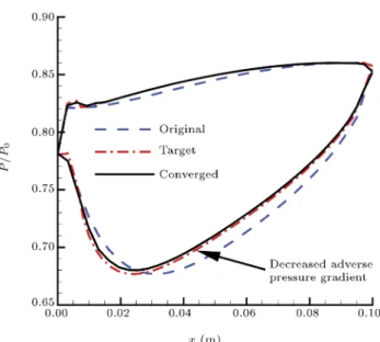
Figure 17. Original, decreased adverse pressure gradient and converged pressure distributions.
Figure 18. Original and new designed airfoils for decreased adverse pressure gradient test case.
For the second applied test case, the pressure distribution of the DCA airfoil is modied to decrease the adverse pressure gradient on the suction side of the airfoil. If separation occurs in the domain, using a lower adverse pressure gradient decreases the size of the recirculating pocket. In Figure 17, the original, target (with lower adverse pressure gradient) and converged pressure distributions are shown. The converged pressure distribution matches the target pressure distribution. The original and designed airfoils are presented in Figure 18.
5. Conclusions
A Ball-Spine (BS) algorithm has been proposed, in this paper, in order to design a compressor blade prole to match a prescribed target pressure distri-bution. A recently developed in-house inviscid ow
solver has been used for this purpose. In the present study, for mesh generation, a combined algebraic-elliptic algorithm has been developed and used. The proposed BS algorithm has been tested on a DCA (target) blade prole, and the achieved geometry shows a good agreement with the target geometry. Starting from two dierent initial geometries, the method has been converged to a blade geometry, which satises the target pressure. After 100 geometry generation steps, the dierence between computed and target pressure distributions are detailed; PD reduces from 13700 Pa to a converged value of 222 Pa. The eect of geometry correction coecient, C, on the stability and convergence of the design procedure has been investigated, and the optimum correction coecient has been obtained.
The method has been applied to a transonic test case, and the accuracy of the method has been veried. As an application, the method has been applied using two new pressure distributions. The rst distribution has a greater loading and the second has a lower adverse pressure gradient on the suction side. The corresponding airfoils satisfying the target pressure distributions have been designed.
Finally, it should be noted that the present ball-spine approach is not limited to application on axial ow compressors. An identical approach can be used for the design of turbines, centrifugal compressors, nozzles, diusers and many more. This task can be performed with some changes in boundary conditions, the solver, the grid generator, and the design algorithm steps. It is general enough to be used in both external and internal ow applications.
Nomenclature
A Element area (m2)
a Acceleration of the ball (m/s2)
C Geometry correction coecient (m2s2/kg)
CPD Computed Pressure Distribution (Pa) E Inviscid ux vectors in x-direction E1 Inviscid ux vectors in -direction
et Total internal energy (J/kg)
F Force imposed on the ball (N) f Filtration coecient
G Inviscid ux vectors in y-direction G1 Inviscid ux vectors in -direction
ht Total enthalpy (J/kg)
J Jacobian of transformation m Ball mass (kg)
P Static pressure (Pa)
Q Conservative vector in physical domain Q1 Conservative vector in computational
domain
T The eigenvector of Jacobian matrix t Time (s), tangential direction TPD Target Pressure Distribution (Pa) u Velocity component in x-direction
(m/s)
v Velocity component in y-direction (m/s)
x Position of the ball (m), x coordinate y Position of the ball (m), y coordinate P Dierence between target and
computed pressures (Pa) PD Dierence between target and
computed pressure distributions (Pa) s Displacement of the ball (m)
t Time step (s) W The wave amplitude
-coordinate in computational domain The angle between force vector and
spine direction (rad)
The eigenvalue of Jacobian matrix -coordinate in computational domain Density (kg/m3)
Subscripts
Back At the outlet
Comp. Computed conditions
E The East face of the control volume L The inner side of the cell face LE Leading Edge
N The north face of the control volume new New conditions
old Old conditions
R The outer side of the cell face rel Relative to the leading edge
S The South face of the control volume Sp Projected on spine direction
Target Target conditions TE Trailing Edge
W The West face of the control volume x x-derivative
y y-derivative
References
1. Li, H-D., He, L., Li, Y-S. and Wells, R.G. \Blad-ing aerodynamics design optimization with mechan-ical and aeromechanmechan-ical constraints", Proceedings of ASME Turbo Expo 2006, Barcelona, Spain, GT2006-90503 (2006).
2. Verstraete, T., Alsalihi, Z. and Van den Braembussche, R.A. \Multidisciplinary optimization of a radial tur-bine for micro gas turtur-bine applications", Proceedings of ASME Turbo Expo 2007, Montreal, Canada, GT2007-27484 (2007).
3. Ghadak, F. \A direct design method based on the laplace and euler equations with application to internal subsonic and supersonic ows", Ph.D. Thesis, Sharif University of Technology, Aero Space Department, Iran (2005).
4. Lamm, P.K. \Inverse problems and Ill-posedness", In-verse Problems in Engineering: Theory and Practice, ASME (1993).
5. Garabedian, P. and McFadden, G. \Design of super-critical swept wings", AIAA Journal, 30(3), pp. 289-291 (1982).
6. Cheng, C.-H. and Wu, C.-Y. \An approach combining body tted grid generation and conjugate gradient methods for shape design in heat conduction prob-lems", Numerical Heat Transfer, Part B, 37(1), pp. 69-83 (2000).
7. Jameson, A. \Optimal design via boundary control", Optimal Design Methods for Aeronautics, AGARD, pp. 3.1-3.33 (1994).
8. Kim, J.S. and Park, W.G. \Optimized inverse design method for pump impeller", Mechanics Research Com-munications, 27(4), pp. 465-473 (2000).
9. Frank, P.D. and Shubin, G.R. \A comparison of optimization-based approach for a model computa-tional aerodynamics design problem", Journal of Com-putational Physics, 98, pp. 74-89 (1992).
10. Dedoussis, V., Chaviaropoulos, P. and Papailiou, K.D. \A fully 3-D inverse method applied to the design of axisymmetric ducts", Proceeding of TURBO EXPO, 37th International Gas Turbine Aeroengine Congress. Expo., Cologne (1992).
11. Dedoussis, V., Chaviaropoulos, P. and Papailiou, K.D. \Rotational compressible inverse design method for two-dimensional, internal ow congurations", AIAA Journal, 31(3), pp. 551-558 (1993).
12. Demeulenaere, A. and Braembussche, R. van den, \Three-dimensional inverse method for turbomachi-nary blading design", ASME Journal of Turbomachi-nary, 120(2), pp. 247-255 (1998).
13. De Vito, L. and Braembuussche, R.V.D. \A novel two-dimentional viscous inverse design method for
turbomachinery blading", Transactions of the ASME, 125, pp. 310-316 (2003).
14. Leonard, O. and BraemBussche, R. \A two-dimensional navier stokes inverse solver for compressor and turbine blade design", Proceeding of the IMECH E part A Journal of Power and Energy, 211, pp. 299-307 (1997).
15. Henne, P.A. \An inverse transonic wing design method", AIAA Paper, pp. 80-0330 (1980).
16. Volpe, G. \Inverse design of airfoil contours: Con-straints, numerical method applications", AGARD, Paper 4 (1989).
17. Barger, R.L. and Brooks, C.W. \A streamline curva-ture method for design of supercritical and subcritical airfoils", NASA TN D-7770 (1974).
18. Malone, J., Vadyak, J. and Sankar, L.N. \Inverse aerodynamic design method for aircraft components", J. Aircraft, 24(1), pp. 8-9 (1986).
19. Malone, J., Vadyak, J. and Sankar, L.N. \A technique for the inverse aerodynamic design of nacelles and wing congurations", AIAA Paper, pp. 85-4096 (1985).
20. Campbell, R.L. and Smith, L.A. \A hybrid algorithm for transonic airfoil and wing design", AIAA Paper, pp. 87-2552 (1987).
21. Bell, R.A. and Cedar, R.D. \An inverse method for the aerodynamic design of three-dimensional aircraft engine nacelles", in Proceedings of the Third Interna-tional Conference on Inverse Design Concepts and Op-timization in Engineering Sciences, ICIDES-III, G.S. Dulikravich, Ed, Washington, D.C., 23-25, October, pp. 405-417 (1991).
22. Malone, J.B., Narramore, J.C. and Sankar, L.N. \An ecient airfoil design method using the Navier-Stokes equations", AGARD, Paper 5 (1989).
23. Malone, J.B., Narramore, J.C. and Sankar, L.N. \Air-foil design method using the Navier-Stokes equations", J. Aircraft, 28(3), pp. 216-224 (1991).
24. Takanashi, S. \Iterative three-dimensional transonic wing design using integral equations", J. Aircraft, 22, pp. 655-660 (1985).
25. Hirose, N., Takanashi, S. and Kawai, N. \Transonic airfoil design procedure utilizing a Navier-Stokes anal-ysis code", AIAA J., 25(3), pp. 353-359 (1987).
26. Dulikravich, G.S. and Baker, D.P. \Aerodynamic shape inverse design using a fourier series method", AIAA Paper, pp. 99-0185 (1999).
27. Nili-Ahmadabadi, M., Durali, M., Hajilouy, A. and Ghadak, F. \Inverse design of 2D subsonic ducts using exible string algorithm", Inverse Problems in Science and Engineering, 17(8), pp. 1037-1057 (2009).
28. Nili-Ahmadabadi, M., Hajilouy, A., Durali, M. and
Ghadak, F. \Duct design in subsonic and supersonic ow regimes with and without normal shock waves us-ing exible strus-ing algorithm", Scientia Iranica Journal, 17(3), pp. 179-193 (2010).
29. Nili-Ahmadabadi, M., Hajilouy, A., Ghadak, F. and Durali, M. \A novel 2-D incompressible viscous inverse design method for internal ows using exible string algorithm", Journal of Fluids Engineering, ASME, 132/031401-1-9 (2010).
30. Nili-Ahmadabadi, M., Durali, M. and Hajilouy, A. \A novel quasi-3D design method for centrifugal com-pressor meridional plane", Proceedings of ASME Turbo Expo 2010, Glasgow, UK, GT2010-23341 (2010).
31. Roe, P.L. \Approximate riemann solvers, parameter vectors and dierence schemes", Journal of Computa-tional Physics, 43, pp. 357-372 (1981).
32. Kermani, M.J. \Development and assessment of up-wind schemes with application to inviscid and viscous ows on structured meshes", Ph.D. Thesis, Depart-ment of Mechanical & Aerospace Engineering, Car-leton University, Canada (2001).
33. Kermani, M.J. and Plett, E.G. \Modied entropy correction formula for the roe scheme", AIAA Paper, pp. 2001-0083 (2001).
34. Emery, J.C., Herrig, L.J., Erwin, J.R. and Felix, A.R. \Systematic two dimensional cascade tests of NACA 65-series compressor blades at low speeds", NACA Reports, 1368 (1957).
35. Homann, K.A. and Chiang, S.T., Computational Fluid Dynamics, I, 4th Ed (2000).
Biographies
Ali Madadi obtained his BS and MS degrees from Sharif University of Technology, Tehran, Iran. His MS thesis concerned the eld of axial ow compressor performance prediction. Currently, he is a PhD degree candidate of Mechanical Engineering at Amirkabir University of Technology, Tehran, Iran, working on the inverse design of axial ow compressor blades. During his PhD program, he and his colleagues developed a three dimensional inviscid ow solver based on the Roe scheme for ow eld analysis of axial ow compressors. The solver is applicable for both rotors and stators, and he has used the solver in the inverse design method to design axial ow compressor blade proles. His research interests include CFD, inverse design and compressible ows.
Mohammad Jafar Kermani obtained his BS de-gree in Mechanical Engineering (Thermal-Fluid) from Shiraz University, Iran, his MS degree in Applied
Mathematics from Manchester University, UK, and his PhD degree from Carleton University, Canada. He also pursued a 21=2 year PDF in UNB, Canada, on steam
turbines and PEMFCs.
Currently he is Associate Professor in Amirkabir University of Technology, Tehran, Iran, and is also taking part in the Alexander von Humboldt Fellow-ship for Experienced Researchers in the Center for Solar Energy and Hydrogen Research, in Ulm, Ger-many.
He has authored 94 papers and supervised 33
graduate students. He is also the recipient of MITACS, rst prize, in 2003, in Halifax, Canada.
Mahdi Nili-Ahmadabadi received his MS and PhD degrees from Sharif University of Technology, Tehran, Iran, in 2005 and 2010, respectively. Currently, he is Assistant Professor and faculty member of the Mechan-ical Engineering Department of the Isfahan University of Technology, in Iran. His major research interests are inverse design, turbomachinery, experimental aerody-namics, and PIV measurement.