Proceedings of the
4th International Workshop on
Multi-Paradigm Modeling
(MPM 2010)
Active Model Patterns with Interactive Model Transformation
Tam´as M´esz´aros and Tiham´er Levendovszky and Gergely Mezei
13 pages
Guest Editors: Vasco Amaral, Hans Vangheluwe, C ´ecile Hardebolle, Lazlo Lengyel Managing Editors: Tiziana Margaria, Julia Padberg, Gabriele Taentzer
Active Model Patterns with Interactive Model Transformation
Tam´as M´esz´aros1and Tiham´er Levendovszky2and Gergely Mezei3
1[email protected],3[email protected]
Department of Automation and Applied Informatics
Budapest University of Technology and Economics, Budapest, Hungary
Institute for Software Integrated Systems Vanderbilt University, Nashville, TN, USA
Abstract: With the proliferation of domain-specific languages, the generalization
of OO patterns is a natural demand. Concepts and tools supporting pattern specifi-cation and execution for arbitrary domain-specific languages facilitate to meet these requirements. Our previous work introduced the Active Model Pattern Infrastructure and possible realizations for its static aspect. In this paper, we contribute a realiza-tion for the operarealiza-tional aspect of the framework. We propose graph rewriting-based interactive model transformation to describe and automate often recurring opera-tional patterns in domain-specific modeling. We have extended a general transfor-mation system with localized application of the rules and facilitate run-time cus-tomization possibilities for the domain engineer to influence the execution of the operations. We can specialize this approach to provide an implementation of the static aspect as well. We have realized our solution in the Visual Modeling and Transformation System.
Keywords:active model patterns, model transformation, VMTS
1
Introduction
Using OO patterns such as design patterns [GHJV95], architectural patterns [Bus96], refactoring operations [Fow99] has considerably simplified the design process of software systems. Patterns provide proven solutions for frequently recurring problems. They are usually described in an intuitive and informal way. For instance many design patterns can be described as an incom-plete UML model fragment that needs to be inserted into the destination class diagram. Code refactoring operations, however, are usually represented with example code fragments and tex-tual explanations. Nowadays, as domain-specific modeling is gaining an increased popularity, a noticeable amount of experience and knowledge have been collected among the experts of the different domains. A straightforward idea is to adapt OO patterns with automated tool support to the practice of domain-specific modeling as well. As Domain-Specific Modeling Languages (DSMLs) are meant to be used in arbitrary domains, thus, in accordance with [LLM09], DSML patterns are referred to asmodel patterns.
operations in a domain-specific environment.
The AMP approach has three orthogonal aspects. The static aspect of AMP realizes the domain-specific static model pattern support. Static model pattern is the common name of domain-specific design patterns, architectural patterns, and patterns in general with arbitrary intention. They can be considered incomplete model fragments that are inserted into the target model. The AMP concept also includes universal design-time model manipulations, which are referred to as theoperational aspectof AMP. Model refactorings or often recurring operation sequences during editing usually cannot be expressed with an incomplete model fragment with the static aspect. The operations can be considered on-demand, localized model transformations applied interactively. They can be realized either by a model transformation environment or by programming the modeling API directly (optionally supported with a proprietary DSL). The third aspect of AMP is thetracing aspect. It covers the detailed logging of model manipulations for certain operations, such as undo/redo purposes.
[LK09] presented two approaches and their realization in the Generic Modeling Environment (GME) [La01] for the application of static model patterns. (i) The first one is based on the extension of the metamodel of the application domain. The pattern infrastructure generates an extended metamodel which is able to store pattern operations (insert/bind/ignore) in addition to the original properties of model elements. Pattern designers must use this specialized metamodel for the definition of patterns. (ii) The other approach uses the original metamodel and DSL to build the patterns, and assigns tags to the model elements to mark the model as a pattern. This solution requires the modeling environment to be able to tag its modeling elements with arbitrary information, even if the structure of the tag is not defined in the metamodel.
In this paper, we present an approach that supports the operational and the static aspects of Active Model Patterns with interactive graph rewriting-based model transformations. Using graph transformations [EEPT06], we could describe active patterns (both static and operational) without using the API of the modeling environment directly. In this case, graph production rules could describe the modifications in a precise way, thus facilitating further analysis on them.
In the following, we shortly illustrate an example domain and model patterns to realize (Sec-tion3.1), then we collect the features that we expect an interactive model transformation envi-ronment to support AMPs (Section3.1). In Section3.2, we illustrate how we have realized the requirements in an existing system. In Section4, we show how we can realize the operational pattern of the case study using the transformation system. Section5presents how the static as-pect of AMPs can be implemented building on the operational asas-pect. Section6summarizes the related work and finally, Section7concludes.
2
Motivation
The motivation of our work is to aid editing Animation Framework (VAF) [MMC09][LM09] models in the Visual Modeling and Transformation System (VMTS)[VMT][LLMC07] with ex-tensive tool support. The VMTS Animation Framework is a flexible framework supporting the real-time animation of models both in their visualized and modeled properties. The architecture of VAF is illustrated in Figure1.
E H_U I ( … ) PNAnimator
PortModels PortViews PortPN PortTimer
P or tM od el s P or tV ie w s EH _P etriN et (… ) P ortP N EH _T im er (… ) P ortT im er Initialize EH_GT PortGT ProcessNextCFEdge ProcessStartNode Matching ApplyCurrentMatch ApplyInternalCausalities ApplyInternalCausality Initialized PreNextCFEdge PostNextCFEdge PreStartNode PostStartNode PreDecision PreEndNode PreRuleNode PreInitMatch PreMatching PreApplyMultipleMatch PreApplyCurrentMatch PreInternalCausalities PreInternalCausality PostInternalCausality PostInternalCausalities PostApplyCurrentMatch PostApplyMultipleMatch PostRuleNode AgsiCFEdge InternalCausalityResult AgsiCFEndNode TrafoOutputPlaces AgsiInternalCausality IAgsiCFNode AgsiRuleExecutionResults
Animator state machine High level animation model
Event handler model Event handler implementation Animated model . Animation engine gen. ref. E N V IR O N M E N T .
PortPN PortTimer PortViews PortModels
GetDiagramView Default
Selecting
GettingView
Highlighting Firing
[no fireable transitions] PortPN:EventGetFireableTransition [fireable transition] PortViews:EventGetView [PortViews:EventGetView_] PortViews:EventHighlight [PortTimer:Tick] [PortTimer:Tick] PortPN:EventFire PortViews:UnHighlight
Figure 1: The Architecture of the VMTS Animation Framework
the model. In our approach, the domain knowledge can be considered a black-box whose in-tegration is supported with visual modeling techniques. Using this approach, we can integrate various simulation frameworks or self-written components with event-driven communication. The animation framework provides three visual languages to describe the dynamic behavior of a metamodeled model, and their processing via an event-driven concept. Eventsare parametriz-able messages that connect the components in our environment. The services of the presentation framework, the domain-specific extensions, possible external simulation engines ( ENVIRON-MENT block in Figure1) are wrapped with event handlers, which provide an event-based in-terface. Communication with event handlers can be established using events. The definition of event handlers and the possible events is supported with a visual language. (Event handler modelin the figure). The default implementation of an event handler can be generated [LM09] based on the interface of the wrapped objects (Implementationblock). The animation logic can be described using an event-driven hierarchical state machine, calledAnimator(Animator state machineblock). The transitions of the state machine are guarded by conditions testing the in-put events and fire other events after performing the transition. The inin-put (outin-put) events of the state machine are created in (sent to) another state machine or an event handler. The events produced by the event handlers and the state machines are scheduled and processed by a DEVS [ZKP00]-based simulator engine (Animation Engine). The event handlers and the state machines are connected through ports in a high-level model (High level animation model).
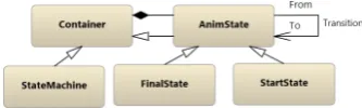
In this paper, we use the previously mentioned state machine language to illustrated our ap-proach of AMPs. The metamodel of this language is depicted in Figure2.
State chart models may contain the usual start as well as end nodes and states (StartState, FinalState,AnimState), the states are connected withTransitionedges. Each transition edge has aGuard and anActionproperty that describe the condition that must be satisfied to perform a transition and the actions to be executed on that transition. States and theStateMachines have a commonContainer ancestor that may contain sub-states through containment edges. Thus, states may be composite as well.
2.1 An Operational Pattern
The example operation we realize with interactive model transformation is the unflattening of the state chart model. More precisely, the selected fragment of the state chart model is turned into a newly created composite state. Those outgoing transitions of the states that have a common Guard andActionproperty and a common target state are replaced with one leaving transition from the composite state. This process is illustrated in Figure3.
Figure 3: State chart unflattening
2.2 A Static Pattern
Figure4illustrates a static pattern for VAF state charts: a frequently used feature is the high-lighting of a model element in a specific state of the state chart if the mouse hovers over the element. Occasionally, there may be multiple highlighted elements as well: [ML08] presents a visual model transformation debugger that highlights the match for a rule element under the mouse cursor after the successful match.
Figure 4: Static pattern to highlight element under mouse cursor
BaseStatecan be considered the default state without highlighting, and if aMouseEnterevent is received, then aHighlight event is sent to the framework and the state machine proceeds to theMouseOverstate. The corresponding guard condition is
PortPeripherals.PeekIsOfType<EHUI.EventMouseEnter>(), and the action script is
Fire(new EHUI.EventHighlight(this, PortPeripherals.
The target of the Highlight event in the action script is theView property of the received MouseEnterevent: it identifies the visual object under the mouse cursor. Similarly, if aMouseLeave event is received, then the respective transition emits anU nHighlight event, and theBaseState becomes active again. Note, thatPortPeripheralsandPortViewsare the conventional names of the ports to send and receive events to/from peripheral devices and the UI in VAF.
In the next sections we discuss the requirements and the conceptual as well as implementation-level solutions to realize tool-support for the introduced operational and static pattern.
3
An Interactive Graph Rewriting-Based Model Transformation
En-gine
We use interactive graph transformation as the execution framework for AMP. By interactive we mean that the domain engineer who executes the pattern application can visually trace and actively influence the behavior of the transformation. In the following we summarize the require-ments and the realization of such a transformation system.
3.1 Requirement specification
We expect an interactive transformation engine to meet the following requirements to facilitate the implementation of the AMP approach.
1. The interactive selection of those model elements that should be involved in the transfor-mation. The input of a usual transformation engine is one or several models. Therefore, we need to identify those elements of these models which may be used during the trans-formation. In case of the state chart unflattening this means the selection of those nodes that should be encapsulated in a composite state.
2. The engineer should be allowed to edit the rewriting rules at runtime: both their attributes and to perform structural changes on the rule.
3. The modeler should be allowed to modify the matches of the rewriting rules interactively. Requirement 2 and 3 is necessary to support static model patterns as shown in Section5: thus we can exactly define how an inserted pattern should join the existing model elements. 4. If a complex model transformation (e.g. a model refactoring) is executed on the host model, it is possible that several branches of the transformation should be enabled or dis-abled according to the intentions of the domain expert. Here we assume that the execution order of the rewriting rules in the transformation is controlled by a control structure. For this purpose, the transformation control should be prepared to mark those branches where the user may have influence on the execution. For example in the state chart unflattening example we may ask the modeler whether to create an explicit start node in the composite state, or rather connect to the first child state of it directly. Depending on the selection of the modeler additional rewriting rules might be executed.
6. Finally, it is not enough to modify the underlying model repository, the changes should be reflected by the visualization as well: of course, deleted elements should be removed from the view, new elements should be displayed, and the changes in the attribute configurations should also be reflected in the visualization.
3.2 Realization of the AMP approach in VMTS
In the following, we guide through the requirements specified in Section3.1, and illustrate with the help of the case studies how we have realized operational active model patterns in VMTS.
The interactive selection of those model elements that should be involved in the transforma-tion. Recall that we suggestlocalizedgraph transformations to describe operational patterns. It is localized, because only several (selected) elements are involved in the transformation, and not the entire model. In VMTS, the model elements selected in the view are marked with a ”se-lected” flag. This flag can then be tested in the transformation, and the matcher can be restricted to find only the marked elements. In our case the flag is stored in a generalTagproperty, which is the member of each model element and is reserved to store arbitrary runtime meta information that is not persisted. In the textual constraints of the rules we may simply test this property. But, because this is a frequently used feature, we have extended the transformation specification language with a flag for the nodes and the edges: if the flag is set on an LHS element, then only the elements from the current selection are matched there.
The engineer should be allowed to edit the rewriting rules at runtime. Note that, because of the interpreted feature of the transformation engine, we may modify the production rules any time during the transformation (if the transformation is paused or waiting for user input), because the rule specifications are processed right when executing them.
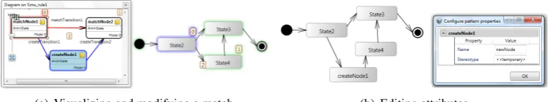
The engineer should be allowed to modify the matches of the rewriting rules interactively. We facilitate the modification of the matching phase on two levels: (i) bind several elements of the rewriting rule to the elements of the host graph, and let the engine finish the match, (ii) and to modify a successful match manually. We provide a visual solution for both of them. Figure
5(a)illustrates a rewriting rule that matches two consecutive states connected with a transition edge (matchNode1,matchTransition1 andmatchNode2), and inserts a new state between the two existing nodes.
(a) Visualizing and modifying a match (b) Editing attributes
Figure 5: Match visualization and attribute editing
hovers the mouse over the pattern item. An existing match can be modified, or an initial match can be defined with the help of the mouse: by clicking on the rule element while holding the Alt button, the pattern element ( matchNode1) receives the focus which is expressed with a red outline. Those elements of the host graph which have a type compatible with that of the pattern element are highlighted with green. By clicking on one of them, the match is changed. Note that even those elements of the pattern that define the creation of a new element ( createNode1 and the connecting edges in the figure) can be bound to existing elements of the host graph this way. Thus the matcher and the rewriting logic is configured to count on them when searching for a valid match, and not to create them in the rewriting phase.
Influencing the execution order of the transformation rules. We have two possibilities to in-fluence the execution order of the rules interactively: (i) because of the interpreted feature of the engine, we can create/delete/reconnect edges in the control flow, provided that the execution is waiting for input or is paused. However, this is not a typical use case, as usually the transforma-tion control should not be directly edited by the user. Instead, (ii) on the edges in the control flow one can create guard expressions and action scripts that prompt for user input and the engine proceeds its execution accordingly.
Asking for optional parameters. If a transformation creates new elements in the host graph, several properties of the new elements may be required to be customized by the user. E.g. the default name of new elements is typically changed right after creation. In order to support this requirement we have slightly modified the transformation definition language and the transfor-mation engine. A new attribute calledPostCon f igurationis added to the possible attributes of the rewriting rule elements. Each item ofPostCon f igurationcouples an attribute name and a de-fault value. After performing a rewriting rule, the marked attributes are listed in a popup window where the user can set all the selected attributes at once (Figure5(b)).
Changes in the model should be reflected in the visualization. As in case of numerous other model transformation environments, the model transformation engine of VMTS modifies the model objects only, but not their visualization. Therefore, we had to extend the interpreted transformation engine to (i) remove deleted edges and nodes, (ii) display newly created edges and nodes and (iii) to place the new elements in a way to follow the layout of the rewriting rule. We also made the coordinates of the model elements accessible in the textual constraints and the imperative code assigned to the rules, thus, they can be used both in the matching phase and edited in the rewriting phase. Furthermore, we apply the data binding features of the underlying UI framework (Windows Presentation Foundation - WPF) of VMTS to reflect attribute changes in the visualization as well.
4
Case study
In the following we present how we have realized the operational pattern outlined in Section2
reconnected to the composite state. Those outgoing transitions of the other selected nodes that also share the action script and have the same target state are removed as well (i.e. the composite state already has those transitions).
Figure 6: Control flow graph of the state chart unflattening transformation
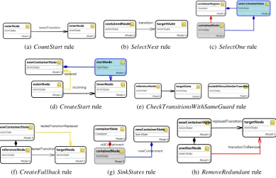
The transformation works as follows. TheCountStartrule (Figure7(a)) matches all the states in the selection (innerNode) that have an incoming transition from a node outside the current selection, and puts those state nodes into a list. This is necessary, because in case the list contains only one element (i.e. one selected node has one incoming edge), we may offer to create a start node inside the composite node, and redirect the incoming edge to the composite node (as shown in Figure3).
(a)CountStartrule (b)SelectNextrule (c)SelectOnerule
(d)CreateStartrule (e)CheckTransitionsWithSameGuardrule
(f)CreateFallbackrule (g)SinkStatesrule (h)RemoveRedundantrule
Figure 7: Rewriting rules to unflatten a state chart diagram
so that they can be identified later. In addition, the container state is positioned and sized to cover the rectangle of the selection, andcontainedNodekeeps its original absolute position in-side it.
The SelectOne rule is left by two flow edges: the guard condition of the one leading to CreateStart (Figure 7(d)) asks the user whether to create an explicit start state within the new composite state. But only ifCountStart found only one selected node with an incoming edge from outside the selection. If there is more than one such node or the user answers ’No’, then the execution proceeds to SelectNextTransition. Otherwise,CreateStart creates a new start state within the composite state, redirects the incoming edge to the composite state, and creates a transition within the start node and the state marked byCountStart.
TheSelectNextTransition,CheckTransitionsWithSameGuardand
CreateFallbackEdgerules iterate through the edges of the reference node, and if the guard ex-pression of either outgoing transition is used for one outgoing transition for each other selected state, then that transition is pushed one level up to the composite state. This means that a tran-sition can be pushed up without changing the semantics of the state chart, if all the selected states have an outgoing transition with the same guard expression. TheSelectNextTransition (Figure7(b)) selects and marks one non-marked outgoing transition of the reference node, then CheckTransitionsWithSameGuard(Figure7(e)) tries to match another selected state without an outgoing transition with the same guard (phrased in the textual constraints of the rule). If it fails, then the transition can be pushed up (CreateFallbackEdgein Figure7(f)). Otherwise, (and also afterCreateFallbackEdge) a new transition is searched for bySelectNextTransition.
If there is not any non-marked outgoing transition for the reference node, then the remaining selected states are moved into the composite state (SinkStates - Figure 7(g)). Finally, RemoveRedundantTransitions(Figure7(h)) removes those outgoing transitions of the selected nodes that have a corresponding outgoing transition on the composite node with the same guard and action expression and target state. Transitions with the same guard, but different action script or target node are left, as they override the behavior of the composite state.
5
Realizing static model patterns as operational patterns
By exploiting the features of the interactive model transformation environment, we can easily realize a static DSML pattern application framework. The key idea is to represent each static DSML pattern as a single rewriting rule (an operational pattern) that creates the elements in the target model, and to execute the rule. As presented in Section3.2we can coordinate the matching phase of the rule, and select those elements which already exist and those elements that should be created and attached to the existing elements. With the help of thePostCon f igurationattribute, we can also select those properties of the inserted nodes and edges that may be customized at insertion time.
matches all the selected edges once (createdEdge), and creates the related rule edges (createdEdgeRule) in the target model. Rule CreatedNodestores the mapping between the elements of the source model (nodeFrom,nodeTo)and the elements of the target rewriting rule (pNodeFrom,pNodeTo), thus,Rule CreatedEdgecan identify the corresponding endpoints of the created rule edge. The imperative code of the resulting rule is also configured to produce the same attribute configura-tion than that of the source model fragment. ThenodeCreated andedgeCreated elements are also flagged (indicated by the gray background) not to be matched again in the same transforma-tion.
(a)CreatedNoderule (b)CreatedEdgerule
Figure 8: Rewriting rules to generate a static pattern insertion rule
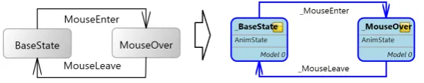
As a result, the transformation generates a rewriting rule that is topologically isomorphic to the selected model fragment, and performs the insertion of the copy of that model fragment into an arbitrary model. This process is illustrated in Figure9for the highlighting pattern.
Figure 9: Composite state initialization pattern
The generated production rule contains one element for each corresponding pattern element: BaseState, MouseOver and the connecting transition edges. TheAction property of each el-ement in the rule is set toCreatedby default, meaning that each element of the pattern will be inserted as a new element in the target model if the rule is executed. However, as we can bind Created elements to existing model elements during the matching phase, we can skip the cre-ation of one or several elements. E.g. if we bind the BaseStatenode of the pattern to an existing host graph element, then it is not created, only the connecting elements.
rule during the transformation, the matches can be shown directly on the source model using the syntax of the source domain. This solution still has two drawbacks: (i) irrelevant parts of the source model are also shown, (ii) if the source model is modified, the mapping may become invalid. To overcome these limitations, we have extended the rule generator transformation to clone the selection, and - in addition to building the rewriting rule - to build a model which contains the selected model fragment only. Then, thePatternTraceattribute of the rule elements point to the elements of this clone model only.
6
Related Work
Since our research is related to DSML patterns, we do not consider UML-based solutions to be the related work of our research. Our previous work [LLM09] provides an extensive summary about UML-based design pattern approaches. To the best of our knowledge, besides VMTS, only GME has published its tool support for domain-specific model patterns to certain extent. A screencast about a promising ongoing research [Rei] on DSM refactorings became available recently, but we found the work unpublished otherwise. However, there are several tools that support some sort of interactive model transformation.
[ZLG05] introduces another GME solution: the Embedded Constraint Language is based on
OCL [OMG06] but has imperative features as well. Using ECL one can describe model refac-torings imperatively. The transformation framework also supports localized execution, however, this approach is rather close to direct API programming.
AToM3[LV02] provides a visual designer to build graph rewriting-based transformations, and facilitates the immediate visualization of the changes performed on the models. Furthermore, we can also access the UI through the API from the rules. However, AToM3does not support localized transformations, and one cannot influence the matching process directly either. The system does not provide a built-in support for static patterns either.
AGG [Tae04] also supports the visual specification of graph rewriting-based model transfor-mations, furthermore, it facilitates the step-by-step execution of both the individual rules and the whole transformation. One can initialize or modify a match manually just like in VMTS, and manually select the rules to execute as well. An AGG based solution [Bie06] suggests graph rewriting to describe inplace model refactorings as well. As AGG has a layered, sequential con-trol flow that does not support user interactions and conditional branchings, thus the engineer has much less influence on the execution order compared to VMTS. Static model pattern support is also a missing feature of AGG.
[TMM07] also suggests graph rewriting-based model transformation for refactoring
opera-tions. The solution generates executable code from the visual specification of the rewriting rules. However, it lacks the possibility to model the execution order of the rules, thus, it needs to be written in plain JAVA.
7
Conclusion
In this paper, we provide a complete framework to define and apply various model patterns with arbitrary intention in a domain-specific environment. We have presented the requirements and the realization in VMTS of an interactive graph rewriting-based model transformation frame-work. We provide possibilities to interactively influence the execution both on high (control flow) and on low (rule) level at runtime. The introduced transformation system serves as the ex-ecution engine for the operational aspect of AMPs that describe frequently used complex model manipulations and refactoring operations in domain-specific modeling. With the specialization of the operational aspect we can easily realize the static aspect of AMPs as well. The presented approach is motivated and illustrated with a case study from the VMTS Animation Framework. Future work contains the design and realization of the tracing aspect of AMPs. Another open issue is how the operational pattern specifications could be generalized, and how the same trans-formation could be applied in different domains by the parameterization of the transtrans-formations.
Acknowledgements: This work is connected to the scientific program of the ”Development of
quality-oriented and harmonized R+D+I strategy and functional model at BME” project. This project is supported by the Hungarian Academy of Sciences - the Office for Subsidised Research Units and by the New Hungary Development Plan (Pr:T ´AMOP-4.2.1/B-09/1/KMR-2010-0002)
Bibliography
[Bie06] E. Biermann et al. EMF Model Refactoring based on Graph Transformation Con-cepts.ECEASST 3, 2006.
[BSM+03] F. Budinsky, D. Steinberg, E. Merks, R. Ellersick, T. J. Grose. Eclipse Modeling Framework. Addison-Wesley Professional, 2003.
[Bus96] F. Buschmann et al.Pattern-Oriented Software Architecture, Volume 1: A System of Patterns. Wiley, Chichester, UK, 1996.
[EEPT06] H. Ehrig, K. Ehrig, U. Prange, G. Taentzer. Fundamentals of Algebraic Graph Transformation (Monographs in Theoretical Computer Science). An EATCS Series. Springer-Verlag New York, Inc., Secaucus, NJ, USA, 2006.
[EWL] Epsilon Wizard Language. http://www.eclipse.org/gmt/epsilon/doc/ewl/.
[Fow99] M. Fowler.Refactoring: Improving the Design of Existing Code. Addison-Wesley, Boston, MA, USA, 1999.
[GHJV95] E. Gamma, R. Helm, R. Johnson, J. Vlissides. Design Patterns: Elements of Reusable Object-Oriented Software. Addison-Wesley, 1995.
[GMF10] Eclipse Graphical Modeling Framework home page. http://www.eclipse.org/gmf, 2010.
[LK09] T. Levendovszky, G. Karsai. An Active Pattern Infrastructure for Domain-Specific Languages.Proceedins of the First International Workshop on Visual Formalisms for Patterns, 2009. in press.
[LLM09] T. Levendovszky, L. Lengyel, T. M´esz´aros. Supporting domain-specific model pat-terns with metamodeling.Software and Systems Modeling8(4):501–520, 2009.
[LLMC07] L. Lengyel, T. Levendovszky, T. M´esz´aros, H. Charaf. Supporting Design Patterns in Graph Rewriting-Based Model Transformation. InInternational Working Conference on Evaluation of Novel Approaches to software Engineering. Barcelona, Spain, 2007.
[LM09] T. Levendovszky, T. M´esz´aros. Tooling the Dynamic Behavior Models of Graphical DSLs. InIn proceedings of the 13th International Conference on Human-Computer Interaction. San Diego, USA, July 2009.
[LV02] J. de Lara, H. Vangheluwe. AToM3: A Tool for Multi-formalism and Meta-modelling. InFASE. Pp. 174–188. 2002.
[ML08] T. M´esz´aros, T. Levendovszky. Visual Specification of a DSL Processor Debugger. In Proceedings of the 8th OOPSLA Workshop on Domain-Specific Modeling. Pp. 67–72. Nashville, USA, 2008.
[MMC09] T. M´esz´aros, G. Mezei, H. Charaf. Engineering the Dynamic Behavior of Metamod-eled Languages.Simulation, Special Issue on Multi-Paradigm Modeling89:793–810, 2009.
[OMG06] OMG. Object Constraint Language, version 2.0. 2006. http://www.omg.org/technology/documents/formal/ocl.htm.
[Rei] J. Reimann. Generic Model Refactoring Based on Roles. http://emftext.org/index.php/Refactoring.
[Tae04] G. Taentzer. AGG: A Graph Transformation Environment for Modeling and Valida-tion of Software. InApplication of Graph Transformations with Industrial Relevance (AGTIVE 2004). LNCS 3062 3062, pp. 446–453. Springer, 2004.
[TMM07] G. Taentzer, D. M¨uller, T. Mens. Specifying Domain-Specific Refactorings for An-droMDA Based on Graph Transformation. InAGTIVE 2007. Lecture Notes in Com-puter Science 5088, pp. 104–119. Springer, 2007.
[VMT] Visual Modeling and Transformation System. http://vmts.aut.bme.hu.
[ZKP00] B. P. Zeigler, T. G. Kim, H. Praehofer.Theory of Modeling and Simulation. Academic Press, Inc., Orlando, FL, USA, 2000.