Lessons Learned Applying
Model-Based System Engineering
Methods to a Strategic Planning Activity
Loyd Baker, Jr.
Vitech Corporation
555 Sparkman Dr., Suite 1213
Huntsville, Alabama 35816
ABSTRACT
A recent strategic planning effort at the Savannah River Nuclear Site successfully utilized a model-based system engineering approach to develop a plan for the disposition of stored nuclear waste material. In the beginning, many team members, as well as program management, did not understand how system engineering methods and tools could possibly help the team accomplish its objectives. The perception was that a system engineering approach was overkill – all that was needed were domain experts, a facilitator, and a scheduling tool. Introduction of the model-based approach improved the team’s ability to communicate their ideas and intentions. This paper presents the lessons learned during the effort to produce a well received strategic plan, including the supporting information data package that justified our conclusions.
INTRODUCTION
In the spring of 1996 a diverse team of engineering/support personnel were assembled to develop a strategic plan for the disposition of nuclear waste stored at the Savannah River Site (SRS). Traditional view-graph engineering methods were used to prepare for the initial briefing to the technical steering committee. The team did
not have a “justification data package” that could answer the following kinds of questions, so the team was directed to develop the missing information:
• What is the basis/rationale for your
decisions, and how do they track back to the customer’s requirements?
• What are the issues, risks, and what
assumptions were made?
• What alternative solutions were
considered?
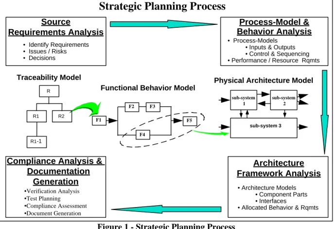
In order to address these questions within the limited time frame (i.e., the end date for the plan could not be changed), the team was augmented with personnel experienced in engineering analysis methods and automated support tools. We used a proven model-based system engineering process to focus team thinking and develop the needed products. The four major activities of the process are illustrated in Figure 1. These activities were performed iteratively, as required, to produce a well defined, completely documented, and optimally
balanced plan. We used the CORE®
PC-based system engineering tool to capture the decisions, perform analyses, and produce review material.
STRATEGIC PLANNING PROCESS After adopting the strategic planning process presented in Figure 1, we found it helped team members focus on the development of
information models that aided in both the understanding of the problem and the development of candidate solutions. These information models proved to be invaluable for:
1. communication between the team
members;
2. automated analysis of proposed
solutions; and
3. automated document generation.
For a discussion of the rationale behind a model-based system engineering process, see the 1996 concept paper prepared by the
Model Driven System Design (MDSD)
INCOSE Working Group (Baker,et al,1996). The key lessons learned are discussed in the context of the strategic planning process activities shown in Figure 1.
Lesson 1: Models provide an improved view of traceability and its evolution. Our initial step involved identifying all the relevant source material from which our set of “starting point” (i.e., originating) requirements should be extracted. As we identified each individual requirement statement, it was recorded in the information
repository as an entity-relation model so we
could establish traceability to other pieces of information (see Figure 2).
Process-Model & Behavior Analysis • Process-Models
• Inputs & Outputs • Control & Sequencing • Performance / Resource Rqmts Source Requirements Analysis • Identify Requirements • Issues / Risks • Decisions Architecture Framework Analysis • Architecture Models • Component Parts • Interfaces
• Allocated Behavior & Rqmts
Physical Architecture Model Traceability Model
Functional Behavior Model
R
R1-1
R1 R2
Compliance Analysis & Documentation
Generation
Strategic Planning Process
•Verification Analysis •Test Planning •Compliance Assessment •Document Generation F1 F5 F2 F3 F4 sub-system 3 sub-system 1 sub-system 2
Issue, Risk Originating Requirement Source Document Trade Study documents generates document by
Note: Labeled Arrows Show Traceability
Figure 2 - Traceability Model The traceability model provided the team a better understanding of the exact set of requirements to be fulfilled and identified issues and risks needing further analysis. We found that this traceability model provided
the team improved visibility over traditional
unstructured text descriptions. In addition to providing a better understanding, the model-based approach aided us in maintaining and changing the traceability models over the life of the effort.
As we proceeded from activity to activity, we added additional detail to our evolving traceability model to include the system and its functions, inputs, and outputs as shown in Figure 3. Issue, Risk Originating Requirement Source Document Trade Study documents generates document by
Note: Labeled Arrows Show Traceability System, Process Function(s) Item(s) performs inputs outputs traces to
Figure 3 - Evolving Traceability Model Lesson 2: Graphical presentation of process flows enable group participation in concurrent engineering.
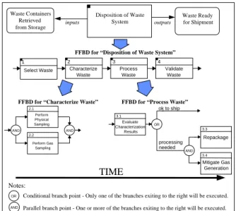
Once the originating requirements were identified, the team used this knowledge base to identify and analyze the set of functions (i.e., units of work) the system/process must perform to satisfy the originating requirements. A Functional Flow Block Diagram (FFBD) technique was used to specify the stimulus-response activity-flow (i.e., conditional sequences of functions or activities) to be performed by the system/process. Sample FFBDs are shown in Figure 4. 1 Select Waste 2 Characterize Waste 3 Process Waste 4 Validate Waste
FFBD for “Disposition of Waste System”
Notes: AND 2.1 Perform Physical Sampling 2.2 Perform Gas Sampling AND
FFBD for “Characterize Waste” Waste Containers
Retrieved
from Storage inputs
Waste Ready for Shipment outputs Disposition of Waste System ok to ship processing needed 3.1 Evaluate Characterization Results OR AND 3.3 Repackage 3.4 Mitigate Gas Generation
FFBD for “Process Waste”
OR Conditional branch point - Only one of the branches exiting to the right will be executed. AND Parallel branch point - One or more of the branches exiting to the right will be executed.
TIME
Figure 4 - Functional Flows
Specifying candidate design solutions as process-flow models made the sequences of required processing explicit. These function-flow “pictures” provided both the development team and customers good visibility allowing everyone to see the proposed solutions and make informed design suggestions. Dynamically creating, updating, and reviewing FFBDs during our meetings enhanced our ability to perform detailed static analysis of the proposed solutions as a group. Once identified, the derived functions were traced back to the originating requirements / assumptions they were developed to satisfy (Figure 5).
Establishing these traceability linkages kept the team focused on identifying only those functions needed to satisfy the originating requirements and was key during the compliance assessment activity.
1 Select Waste 2 Characterize Waste 3 Process Waste 4 Validate Waste Assumption traced from traced from Source Document Originating Requirement Trade Study documented by documented by
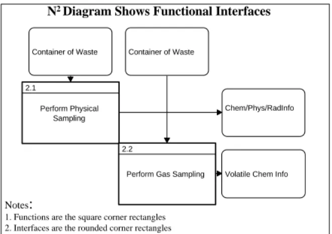
Note: Labeled Arrows Show Traceability Figure 5 - Traceability Model Updates Lesson 3: Models provide improved insight in the derivation of interfaces. Once the Process-Flow Model was established (i.e., FFBDs created), it was partitioned into individual “processing-paths” that could be allocated to (i.e., assigned to) the system’s component parts (see Figure 6). In other words, we identified the physical entities that were going to perform specific processing.
Business / System Physical Architecture
sub-system 3 sub-system 1 sub-system 2 Task 3 Task 2 Task 1 Task 4 Task 5 Behavior Model
Figure 6 - Allocation of Processing to Physical Architecture Model
The allocation process exposed the
interfacing items flowing between the system’s physical architecture component
parts. We used an N2 Diagram view to
communicate the interfaces as shown in Figure 7.
Container of Waste Container of Waste
Chem/Phys/RadInfo 2.1
Perform Physical Sampling
Volatile Chem Info 2.2
Perform Gas Sampling
Notes:
1. Functions are the square corner rectangles 2. Interfaces are the rounded corner rectangles
N2 Diagram Shows Functional Interfaces
Figure 7 - Interface Diagram Once the desired set of functions and interfaces were defined, the schedule activities needed to develop the strategic plan schedule were added to the traceability model as shown in Figure 8.
TRU Waste Disposition System Source Documents documents Function performs Activity implements Issue, Assumptions generates Originating Requirements traces to Trade Study inputs / outputs documented by Item
Figure 8 - Schedule Activities Added To Traceability Model
Lesson 4: Automated documentation generation from models produces up-to-date documentation on demand at low cost.
The CORE tool’s automatic document
generation capability was used to produce various kinds of traceability compliance tables for inclusion in the “justification data package” to be delivered along with the Strategic Plan. The required compliance documentation was generated from the
Traceability, FFBD, and Interface models stored in the information repository.
Because the compliance documentation was generated as Rich Text Format (RTF) electronic files, project personnel were able to share any textual, tabular, or graphical data stored in the information repository with organizations using different tools. We found that automatic generation of documents from the information database eliminated, or at least greatly reduced, the need to manually build project review material. This produced significant savings in terms of both time and resources.
The “justification data package” generated in support of our strategic plan can be found in the “Supporting Documentation For TRU Waste Disposition Program” (TRU Waste Strategic Plan Task Team, 1996).
CONCLUSION
The Strategic Planning Process summarized in this paper was based on proven model-based system engineering methods and a commercially available support tool-set. The process was designed to provide a focused approach for identifying the activities that must be completed, including consideration of alternatives and key decisions that must be made, and a proposed implementation schedule.
The lessons learned using this model-based approach were as follows:
• Models provide an improved view of
traceability and its evolution
• Graphical presentation of process
flows enable group participation in concurrent engineering
• Models provide improved insight in
the derivation of interfaces
• Automated documentation from
models produces up-to-date documentation on demand at low cost
We found the level of understanding and the sharing of ideas increased dramatically over the traditional view-graph and textual description approach used at the beginning of the task.
REFERENCES
Baker, Loyd, Clemente, Paul, Cohen, Bob, Permenter, Larry, Purves, Byron, and Salmon, Pete; “Foundation Concepts For Model Driven System Design”; INCOSE Working Group White Paper for 1996 International Symposium -- Volume II of Proceedings.
TRU Waste Strategic Plan Task Team, “Supporting Documentation For TRU Waste Disposition Program”; WSRC-RP-96-488, October 24, 1996.
ABOUT THE AUTHOR
Loyd Baker, Jr. is a Principal Engineer for
Vitech Corporation, and serves as the co-chair of the INCOSE Model Driven System Design Working Group.