BARB [email protected]
RFCOMM WITH TS 07.10
Serial Port Emulation
Abstract
This document specifies the RFCOMM protocol by specifying a
subset of the ETSI TS 07.10 standard, along with some
Revision History
Revision Date Comments
V11 22 February 2001 Version released with Bluetooth Core Specification V1.1.
D12r00 15 August 2005 Edited specification for v1.2 or Later updates
D12r01 14 September 2005 Editorial updates
D12r02 31 October 2005 Editorial updates
D12r03 15 November 2005 Editorial updates
D12r04 20 March 2006 Editorial updates
D12r05 23 June 2006 Technical change, section 6.3
D12r06 01 August 2007 Technical changes to section 6.1 and 7.3.1
D12r07 09 August 2007 Errata 364; Fix table reference in Section 5.5.3 to Table 5.1
D12r08 01 Oct 2007 Incorporate IEEE language changes
D12r09 01 May 2012 Address comments in D12r08-AB-Terry+TBH4 version
D12r10 02 May 2012 Changed TS 07.10 to GSM 07.10
D12r11 03 May 2012 Addressed remaining comments. Spell checked and corrected
grammar per grammar checker.
D12r12 31 May 2012 Fix minor editorial errors found by CC and HY. See comments.
D12r13 11 June 2012 Redraw Figure 2.2; Update reference from EIATIA-232 to
ITU-TV.24
D12r14 12 July 2012 Edits based on further BARB review
D12r15 13 July 2012 Edits based on further BARB review
V12 06-Nov 2012 Adopted by the Bluetooth SIG Board of Directors
Contributors
Name Company
Christian Andersson (EC 14) Telefonaktiebolaget LM Ericsson
Ingemar Nilsson Telefonaktiebolaget LM Ericsson
Patrik Olsson Telefonaktiebolaget LM Ericsson
Gerrit Slot Telefonaktiebolaget LM Ericsson
Johan Sšrensen (Section Owner) Telefonaktiebolaget LM Ericsson
Donald Liechty (EC 14) Extended Systems
Robert Hunter (EC 14) Intel Corporation
Srikanth Kambhatla Intel Corporation
Stan Adermann (EC 14) Microsoft Corporation
Michael Camp Nokia Mobile Phones
Pere(PR14) Godia-Canero (EC 14) Nokia Mobile Phones
Riku MettŠlä Nokia Mobile Phones
Disclaimer and Copyright Notice
The copyright in this specification is owned by the Promoter Members of Bluetooth® Special Interest Group (SIG), Inc. (“Bluetooth SIG”). Use of these specifications and any related intellectual property (collectively, the
“Specification”), is governed by the Promoters Membership Agreement among the Promoter Members and
Bluetooth SIG (the “Promoters Agreement”), certain membership agreements between Bluetooth SIG and its Adopter and Associate Members (the “Membership Agreements”) and the Bluetooth Specification Early Adopters Agreements (1.2 Early Adopters Agreements) among Early Adopter members of the unincorporated
Bluetooth SIG and the Promoter Members (the “Early Adopters Agreement”). Certain rights and obligations of
the Promoter Members under the Early Adopters Agreements have been assigned to Bluetooth SIG by the Promoter Members.
Use of the Specification by anyone who is not a member of Bluetooth SIG or a party to an Early Adopters Agreement (each such person or party, a “Member”), is prohibited. The legal rights and obligations of each Member are governed by their applicable Membership Agreement, Early Adopters Agreement or Promoters Agreement. No license, express or implied, by estoppel or otherwise, to any intellectual property rights are granted herein.
Any use of the Specification not in compliance with the terms of the applicable Membership Agreement, Early Adopters Agreement or Promoters Agreement is prohibited and any such prohibited use may result in termination of the applicable Membership Agreement or Early Adopters Agreement and other liability permitted by the applicable agreement or by applicable law to Bluetooth SIG or any of its members for patent, copyright and/or trademark infringement.
THE SPECIFICATION IS PROVIDED “AS IS” WITH NO WARRANTIES WHATSOEVER, INCLUDING ANY WARRANTY OF MERCHANTABILITY, NONINFRINGEMENT, FITNESS FOR ANY PARTICULAR PURPOSE, SATISFACTORY QUALITY, OR REASONABLE SKILL OR CARE, OR ANY WARRANTY ARISING OUT OF ANY COURSE OF DEALING, USAGE, TRADE PRACTICE, PROPOSAL, SPECIFICATION OR SAMPLE. Each Member hereby acknowledges that products equipped with the Bluetooth technology ("Bluetooth
products") may be subject to various regulatory controls under the laws and regulations of various governments worldwide. Such laws and regulatory controls may govern, among other things, the combination, operation, use, implementation and distribution of Bluetooth products. Examples of such laws and regulatory controls include, but are not limited to, airline regulatory controls, telecommunications regulations, technology transfer controls and health and safety regulations. Each Member is solely responsible for the compliance by their
Bluetooth Products with any such laws and regulations and for obtaining any and all required authorizations, permits, or licenses for their Bluetooth products related to such regulations within the applicable jurisdictions. Each Member acknowledges that nothing in the Specification provides any information or assistance in connection with securing such compliance, authorizations or licenses. NOTHING IN THE SPECIFICATION CREATES ANY WARRANTIES, EITHER EXPRESS OR IMPLIED, REGARDING SUCH LAWS OR REGULATIONS.
ALL LIABILITY, INCLUDING LIABILITY FOR INFRINGEMENT OF ANY INTELLECTUAL PROPERTY RIGHTS OR FOR NONCOMPLIANCE WITH LAWS, RELATING TO USE OF THE SPECIFICATION IS EXPRESSLY DISCLAIMED. BY USE OF THE SPECIFICATION, EACH MEMBER EXPRESSLY WAIVES ANY CLAIM
AGAINST BLUETOOTH SIG AND ITS PROMOTER MEMBERS RELATED TO USE OF THE
SPECIFICATION.
Bluetooth SIG reserve the right to adopt any changes or alterations to the Specification as it deems necessary or appropriate.
Copyright © 2012. Bluetooth® SIG, Inc. All copyrights in the Bluetooth Specifications themselves are owned by Ericsson AB, Lenovo (Singapore) Pte. Ltd., Intel Corporation, Microsoft Corporation, Motorola Mobility, Inc., Nokia Corporation, and Toshiba Corporation.
Contents
1 Introduction ... 5
1.1 Overview ... 5
1.2 Device Types ... 5
1.3 Byte Ordering... 6
2 RFCOMM Service Overview ... 7
2.1 RS-232 Control Signals ... 7
2.2 Null Modem Emulation ... 7
2.3 Multiple Emulated Serial Ports ... 8
2.3.1 Multiple Emulated Serial Ports between two Devices ... 8
2.3.2 Multiple Emulated Serial Ports and Multiple Bluetooth Devices ... 9
3 Service Interface Description ... 11
3.1 Service Definition Model ... 11
4 GSM 07.10 Subset Supported by RFCOMM ... 12
4.1 Options and Modes ... 12
4.2 Frame Types... 12
4.3 Commands ... 12
4.4 Convergence Layers ... 13
5 GSM 07.10 Adaptations for RFCOMM ... 14
5.1 Media Adaptation ... 14
5.1.1 FCS calculation ... 14
5.1.2 P/F-Bit ... 14
5.1.3 CR Bit ... 14
5.2 GSM 07.10 Multiplexer Start-up and Closedown Procedure ... 15
5.2.1 Start-up Procedure ... 15
5.2.2 Close-down Procedure ... 16
5.2.3 Link Loss Handling ... 16
5.3 System Parameters ... 16
5.4 DLCI allocation with RFCOMM Server Channels... 17
5.5 Multiplexer Control Commands ... 17
5.5.1 Remote Port Negotiation Command (RPN) ... 18
5.5.2 Remote Line Status Command (RLS) ... 18
5.5.3 DLC Parameter Negotiation (PN) ... 18
6 Flow Control ... 21
6.1 L2CAP Flow Control in Overview ... 21
6.2 Wired Serial Port Flow Control ... 21
6.3 GSM 07.10 Flow Control ... 21
6.4 Port Emulation Entity Serial Flow Control ... 22
6.5 Credit Based Flow Control ... 22
6.5.1 Initial DLC Negotiation ... 23
6.5.2 DLC Operation ... 23
6.5.3 Other Flow Control Aspects ... 24
7 Interaction with Other Entities ... 25
7.1 Port Emulation and Port Proxy Entities ... 25
7.1.1 Port Emulation Entity... 25
7.1.2 Port Proxy Entity ... 25
7.2 Service Registration and Discovery ... 25
7.3 Lower Layer Dependencies ... 27
7.3.1 Reliability ... 27
7.3.2 Low Power Modes... 27
8 References ... 28
1
Introduction
The RFCOMM protocol provides emulation of serial ports over the L2CAP protocol [2]. The protocol is based on the ETSI standard GSM 07.10 [1]. This document does not contain a complete specification. Instead, references are made to the relevant parts of the GSM 07.10 standard. Only a subset of the GSM 07.10 standard is used, and some adaptations of the protocol are specified in this document. Furthermore, an RFCOMM - specific extension is added, in the form of a mandatory credit based flow control
scheme.
1.1 Overview
RFCOMM is a simple transport protocol, with additional provisions for emulating the nine circuits of RS-232 (ITU-T V.24) serial ports.
The RFCOMM protocol supports up to 60 simultaneous connections between two Bluetooth devices. The number of connections that may be used simultaneously in a Bluetooth device is implementation-specific.
1.2 Device Types
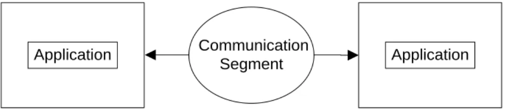
For the purposes of RFCOMM, a complete communication path involves two applications running on different devices (the communication endpoints) with a
communication segment between them. Figure 1.1 shows the complete communication
path. (In this context, the term application may mean other things than end-user application; e.g. higher layer protocols or other services acting on behalf of end-user applications.)
A Communication Device B
Segment
Application Application
Figure 1.1: RFCOMM Communication Segment
RFCOMM is intended to cover applications that make use of the serial ports of the devices in which they reside. In the simple configuration, the communication segment is a Bluetooth link from one device to another (direct connect), see Figure 1.2. Where the communication segment is another network, Bluetooth wireless technology is used for the path between the device and a network connection device like a modem. RFCOMM is only concerned with the connection between the devices in the direct connect case, or between the device and a modem in the network case. RFCOMM can support other configurations, such as modules that communicate via Bluetooth wireless technology on one side and provide a wired interface on the other side, as shown in Figure 1.3. These
devices are not really modems but offer a similar service. They are therefore not explicitly discussed here.
This specification supports implementation of the following two device types: • Type 1 devices are communication endpoints such as computers and printers. • Type 2 devices are those that are part of the communication segment; e.g. modems. Though RFCOMM does not make a distinction between these two device types in the protocol, accommodating both types of devices impacts the RFCOMM protocol.
Device A with Bluetooth (Type 1)
Device A with Bluetooth (Type 2) BT
Figure 1.2: RFCOMM Direct Connect
Device A with Bluetooth (Type 1)
Device A with Bluetooth (Type 2)
BT Device C
(non Bluetooth) Wire
Figure 1.3: RFCOMM used with legacy COMM device
The information transferred between two RFCOMM entities has been defined to support both type 1 and type 2 devices. Some information is only needed by type 2 devices while other information is intended to be used by both. In the protocol, no distinction is made between type 1 and type 2. It is therefore up to the RFCOMM implementers to determine if the information passed in the RFCOMM protocol is of use to the
implementation. Since the device is not aware of the type of the other device in the communication path, each shall pass on all available information specified by the protocol.
1.3 Byte Ordering
This document uses the same byte ordering as the GSM 07.10 specification; i.e. all binary numbers are in Least Significant Bit to Most Significant Bit order, reading from left to right.
2
RFCOMM Service Overview
RFCOMM emulates RS-232 (ITU-T V.24) serial ports. The emulation includes transfer of the state of the non-data circuits. RFCOMM has a built-in scheme for null modem emulation.
In the event that a baud rateis set for a particular port through the RFCOMM service interface, that will not affect the actual data throughput in RFCOMM; i.e. RFCOMM does not incur artificial rate limitation or pacing. However, if either device is a type 2 device (relays data onto other media), or if data pacing is done above the RFCOMM service interface in either or both ends, actual throughput will, on average, reflect the baud rate setting.
RFCOMM supports emulation of multiple serial ports between two devices and emulation of serial ports between multiple devices, see section 2.3.
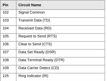
2.1 RS-232 Control Signals
RFCOMM emulates the nine circuits of an RS-232 interface. The circuits are listed in
Table 2.1.
Pin Circuit Name
102 Signal Common
103 Transmit Data (TD)
104 Received Data (RD)
105 Request to Send (RTS)
106 Clear to Send (CTS)
107 Data Set Ready (DSR)
108 Data Terminal Ready (DTR)
109 Data Carrier Detect (CD)
125 Ring Indicator (RI)
Table 2.1: Emulated RS-232 circuits in RFCOMM
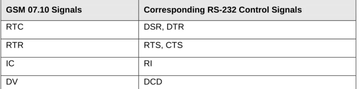
2.2 Null Modem Emulation
RFCOMM is based on GSM 07.10. When it comes to transfer of the states of the
non-data circuits, GSM 07.10 does not distinguish between DTE and DCE devices. The
RS-232 control signals are sent as a number of DTE/DCE independent signals; see Table 2.2.
GSM 07.10 Signals Corresponding RS-232 Control Signals
RTC DSR, DTR
RTR RTS, CTS
IC RI
DV DCD
Table 2.2: GSM 07.10 Serial Port Control Signals
The way in which GSM 07.10 transfers the RS-232 control signalscreates an implicit null modemwhen two devices of the same kind are connected together. Figure 2.1
shows the null modem that is created when two DTE are connected via RFCOMM. No single null-modem cable-wiring scheme works in all cases; however, the null modem scheme provided in RFCOMM should work in most cases.
FG 1 TD 2 RD 3 RTS 4 CTS 5 DSR 6 SG 7 CD 8 DTR 20 RI 22 FG 1 TD 2 RD 3 RTS 4 CTS 5 DSR 6 SG 7 CD 8 DTR 20 RI 22 ‘ON’ ‘OFF’ ‘ON’ ‘OFF’
Figure 2.1: RFCOMM DTE–DTE Null Modem Emulation
2.3 Multiple Emulated Serial Ports
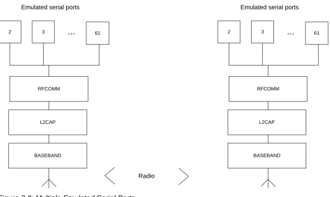
2.3.1 Multiple Emulated Serial Ports between two Devices
Two Bluetooth devices using RFCOMM in their communication may open multiple emulated serial ports. RFCOMM supports up to 60 open emulated ports; however, the number of ports that can be used in a device is implementation-specific.
A Data Link Connection Identifier(DLCI) GSM 07.10 identifies an ongoing connection between a client and a server application. The DLCI is represented by 6 bits, but its usable value range is 2…61; in GSM 07.10, DLCI 0 is the dedicated control channel, DLCI 1 is unusable due to the concept of Server Channels, and DLCIs 62-63 are
reserved. The DLCI is unique within one RFCOMM sessionbetween two devices. (This
is explained further in section 2.3.2) To account for the fact that both client and server applications may reside on both sides of an RFCOMM session, with clients on either side making connections independent of each other, the DLCI value space is divided
between the two communicating devices using the concept of RFCOMM server channels. This is further described in 5.4: DLCI allocation with RFCOMM Server Channels.
2 3 ... 61
RFCOMM
L2CAP
BASEBAND Emulated serial ports
2 3 ... 61
RFCOMM
L2CAP
BASEBAND Emulated serial ports
Radio
Figure 2.2: Multiple Emulated Serial Ports.
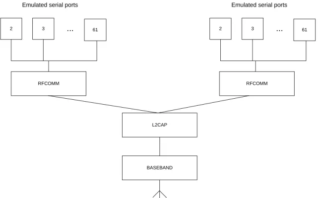
2.3.2 Multiple Emulated Serial Ports and Multiple Bluetooth Devices
If a Bluetooth device supports multiple emulated serial ports and the connections are allowed to have endpoints in different Bluetooth devices, then the RFCOMM entity must be able to run multiple GSM 07.10 multiplexer sessions, see Figure 2.3. Note that each multiplexer session is using its own L2CAP channel ID (CID). The ability to run multiple sessions of the GSM 07.10 multiplexeris optional for RFCOMM.
2 3 ... 61
RFCOMM
L2CAP
BASEBAND
Emulated serial ports
2 3 ... 61
Emulated serial ports
RFCOMM
3
Service Interface Description
RFCOMM is a protocol used to emulate serial ports. In most systems, RFCOMM will be part of a port driver that includes a serial port emulation entity.
3.1 Service Definition Model
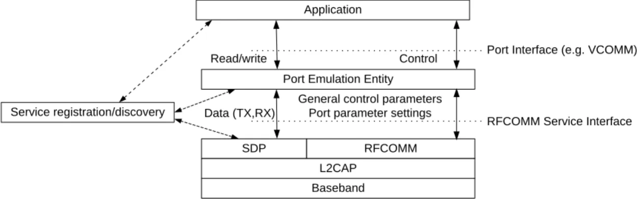
Figure 3.1 shows a model of how RFCOMM fits into a typical system. This figure represents the RFCOMM reference model.
Port Emulation Entity
SDP RFCOMM L2CAP Baseband Service registration/discovery Application Data (TX,RX)
General control parameters Port parameter settings
RFCOMM Service Interface Control
Read/write Port Interface (e.g. VCOMM)
Figure 3.1: RFCOMM reference model
The elements of the RFCOMM reference model are described below.
Element Description
Application Applications that utilize a serial port communication interface Port Emulation
Entity
The port emulation entity maps a system-specific communication interface (API) to the RFCOMM services. The port emulation entity plus RFCOMM make up a port driver
RFCOMM Provides a transparent data stream and control channel over an
L2CAP channel. Multiplexes multiple emulated serial ports Service
Registration/ Discovery
Server applications register here on local device, and it provides services for client applications to discover how to reach server applications on other devices
L2CAP Protocol multiplexing, SAR
4
GSM 07.10 Subset Supported by RFCOMM
4.1 Options and Modes
RFCOMM uses the basic optionof GSM 07.10.
4.2 Frame Types
Table 4.1 shows the GSM 07.10 frame typesthat are supported in RFCOMM.
Frame Types
Set Asynchronous Balanced Mode (SABM) command Unnumbered Acknowledgement (UA) response Disconnected Mode (DM) response
Disconnect (DISC) command
Unnumbered information with header check (UIH) command and response
Table 4.1: Supported frame types in RFCOMM
The ’Unnumbered Information (UI) command and response’ are not supported by RFCOMM. Since the error recovery mode option of the GSM 07.10 protocol is not used in RFCOMM none of the associated frame types are supported.
4.3 Commands
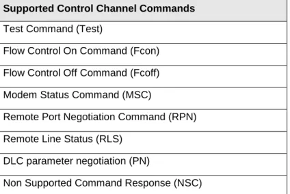
GSM 07.10 defines a multiplexer that has a dedicated control channel, DLCI 0. The control channel is used to convey information between two multiplexers. The following
commands in GSM 07.10are supported by RFCOMM:
Supported Control Channel Commands
Test Command (Test)
Flow Control On Command (Fcon) Flow Control Off Command (Fcoff) Modem Status Command (MSC)
Remote Port Negotiation Command (RPN) Remote Line Status (RLS)
DLC parameter negotiation (PN)
Non Supported Command Response (NSC)
Whenever a non-supported command type is received a ’Non-Supported Command Response (NSC)’ shall be sent.
4.4 Convergence Layers
RFCOMM only supports the type 1 convergence layerin GSM 07.10.
The Modem Status Command(MSC) shall be used to convey the RS-232 control
5
GSM 07.10 Adaptations for RFCOMM
5.1 Media Adaptation
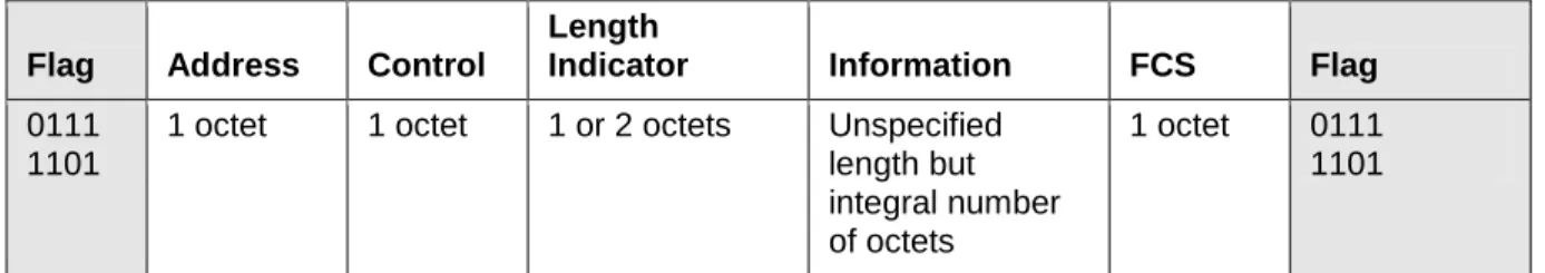
The opening flag and the closing flags in the GSM 07.10 basic option frame are not used in RFCOMM. Instead, only the fields contained between the flags are exchanged
between the L2CAP layer and RFCOMM layer; see Figure 5.1.
There is always exactly one RFCOMM frame contained in each L2CAP frame.
Flag Address Control
Length
Indicator Information FCS Flag
0111 1101
1 octet 1 octet 1 or 2 octets Unspecified
length but integral number of octets
1 octet 0111
1101
Figure 5.1: Frame Structure for Basic option
Note that the opening and closing flags from the GSM 07.10 Basic option are excluded in RFCOMM.
5.1.1 FCS calculation
In GSM 07.10, the frame check sequence (FCS) is calculated on different sets of fields for different frame types. These are the fields that the FCS is calculated on:
• For SABM, DISC, UA, DM frames: on Address, Control and Length field. • For UIH frames: on Address and Control field.
(This is stated here for clarification, and to set the standard for RFCOMM; the fields included in FCS calculation have actually changed in version 7.0.0 of GSM 07.10, but RFCOMM will not change the FCS calculation scheme from the one above.)
5.1.2 P/F-Bit
In the control field (see Figure 5.1), there is one bit denoted as the P/F-bit. The general function of this bit is explained in GSM 07.10 [1], section 5.4.4. In addition, the value to use for the P/F-bit in UIH frames is further clarified in GSM 07.10 [1], section 5.4.3.1. These rules apply without modification on an RFCOMM session where the credit based flow control scheme is not in use. See 6.5: Credit Based Flow Control.
However, when credit based flow control is in use, the meaning of the P/F-bit is redefined for UIH frames. This also involves a redefinition of the frame structure, compared to Figure 5.1. See DLC Op for further details.
5.1.3 CR Bit
In GSM 07.10, there are two different C/R-bits, one in the frame level (in the address field of the frame header), and one in the message level (in the command type field of the commands sent on the multiplexer control channel). The C/R bit in the frame level is set independently of the C/R bit in the message level.
In the frame level, the C/R bit in the frame header is set as follows:
• For SABM, UA, DM and DISC frames C/R bit is set according to Table 1 in GSM 07.10 [1], section 5.2.1.2
• For UIH frames, the C/R bit is always set according to section 5.4.3.1 in GSM 07.10
[1]. This applies independently of what is contained within the UIH frames, either data or control messages.
In the message level, the C/R bit in the command type field is set as stated in section 5.4.6.2 in GSM 07.10 [1]. Control messages are sent in UIH frames, where the C/R bit in the address field of the frame header is always set according to section 5.4.3.1 in GSM 07.10 [1], independently of whether the control message is a command or a response.
5.2 GSM 07.10 Multiplexer Start-up and Closedown Procedure
The start-up and closedown procedures as specified in section 5.7 in GSM 07.10 are
not supported. This means that the AT-command AT+CMUXis not supported by
RFCOMM, neither is the multiplexer close down (CLD) command.
At any time, there shall be at most one RFCOMM sessionbetween any pair of devices. When establishing a new DLC, the initiating entity shall check if there already exists an RFCOMM session with the remote device, and if so, establish the new DLC on that. A session is identified by the Bluetooth BD_ADDR of the two endpoints1.
5.2.1 Start-up Procedure
The device opening up the first emulated serial port connection between two devices is responsible for first establishing the multiplexer control channel. It shall:
• Establish an L2CAP channel to the peer RFCOMM entity, using L2CAP service primitives; see L2CAP “Service Primitives.”
• Start the RFCOMM multiplexer by sending SABM command on DLCI 0, and await UA response from peer entity. (Further optional negotiation steps are possible.) After these steps, DLCs for user data traffic may be established.
Implementation note: There is a special case that can occur if two RFCOMM entities try to establish a session at the same time on an already existing baseband connection. This will be experienced by an RFCOMM entity as receiving a L2CAP connect indication after it has itself issued a L2CAP connect request. In this situation, the RFCOMM entity shall respond negatively to the received connect indication (since there may only be one session between two RFCOMM entities). How the situation is resolved is up to the
1 This implies that, when responding to an L2CAP connection indication, the RFCOMM entity should save and associate the new RFCOMM session with the remote BD_ADDR. This is, at least, necessary if subsequent establishment of a DLC in the opposite direction is possible (which may depend on device capabilities).
implementation (e.g., it may retry after a random time, or leave it up to the user to retry manually).
5.2.2 Close-down Procedure
The device closing the last connection (DLC) on a particular session shall close the multiplexer by closing the corresponding L2CAP channel.
Prior to closing the L2CAP channel, the device closing the last connection may send a DISC command on DLCI 0. The other device shall respond to the DISC with a UA response.
5.2.3 Link Loss Handling
If an L2CAP link loss notificationis received, the local RFCOMM entity is responsible for sending a connection loss notification to the port emulation/proxy entity for each active DLC. Then all resources associated with the RFCOMM session should be freed.
The appropriate action to take in the port emulation/proxy entity depends on the API on top. For example, for an emulated serial port (vCOMM), it would be suitable to drop CD, DSR and CTS signals (assuming device is a DTE).
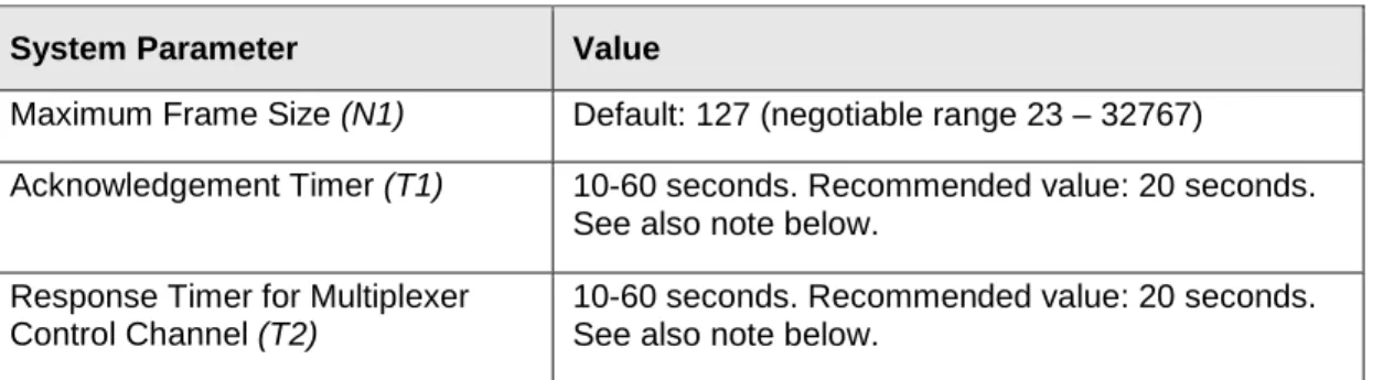
5.3 System Parameters
Table 5.1 contains all the applicable system parameters for the RFCOMM implementation of the GSM 07.10 multiplexer.
System Parameter Value
Maximum Frame Size (N1) Default: 127 (negotiable range 23 – 32767)
Acknowledgement Timer (T1) 10-60 seconds. Recommended value: 20 seconds.
See also note below. Response Timer for Multiplexer
Control Channel (T2)
10-60 seconds. Recommended value: 20 seconds. See also note below.
Table 5.1: System parameter values
Note: The timer T1 is the timeout for frames sent with the P/F-bit set to one (this applies only to SABM and DISC frames in RFCOMM). T2 is the timeout for commands sent in UIH frames on DLCI 0. The exact timeout values are implementation dependent, and can be chosen within the ranges indicated above. However, when sending an SABM frame to start a new DLC (with DLCI > 0) T1 shall be set in the interval 60 - 300 seconds (again, with exact value being implementation dependent).
Since RFCOMM relies on lower layers to provide reliable transmission, the default action performed on timeouts is to close down the multiplexer session.
On the responding side, if authentication procedures are triggered from RFCOMM, this shall only be done when receiving a SABM frame, not when receiving configuration commands preparing an unopened DLC.
5.4 DLCI allocation with RFCOMM Server Channels
To account for the fact that both client and server applications may reside on both sides of an RFCOMM session, with clients on either side making connections independent of each other, the DLCI value space is divided between the two communicating devices using the concept of RFCOMM server channelsand a direction bit.
The RFCOMM server channel number is a subset of the bits in the DLCI part of the address field in the GSM 07.10 frame.
Bit No. 1 2 3 4 5 6 7 8
GSM 07.10 EA C/R DLCI
RFCOMM EA C/R D Server Channel
Table 5.2: The format of the Address Field
Server applications registering with an RFCOMM service interface are assigned a Server Channel number in the range 1…30. [0 and 31 shall not be used since the corresponding DLCIs are reserved in GSM 07.10]. This value shall be registered in the Service Discovery Database; see Service Registration and Discovery.
For an RFCOMM session, the initiating device is given the direction bit D=1 (and conversely, D=0 in the other device). When establishing a new data link connection on an existing RFCOMM session, the direction bit is used in conjunction with the Server Channel to determine the DLCI to use to connect to a specific application. This DLCI is thereafter used for all packets in both directions between the endpoints.
In effect, this partitions the DLCI value space such that server applications on the non-initiating device are reachable on DLCIs 2,4,6,…,60; and server applications on the initiating device are reachable on DLCIs 3,5,7,…,61. (Note that for a device that supports multiple simultaneous RFCOMM sessions to two or more devices, the direction bit might not be the same on all sessions.)
An RFCOMM entity making a new DLC on an existing session forms the DLCI by
combining the Server Channel for the application on the other device, and the inverse of its own direction bit for the session.
DLCIs 1 and 62-63 are reserved and never used in RFCOMM.
5.5 Multiplexer Control Commands
Note that in GSM 07.10, some Multiplexer Control commandspertaining to specific DLCIs may be exchanged on the control channel (DLCI 0) before the corresponding DLC has been established. (This refers to the PN and RPN commands.) All such states associated with an individual DLC shall be reset to their default values upon receiving a DISC commandframe, or when closing the DLC from the local side. This is to ensure that all DLC (re)establishments on the same session will have predictable results, irrespective of the session history.
If a Multiplexer Control command is received relating to a DLCI that is not open, the responding implementation may replace the "proper" response on the Multiplexer
Control channel with a DM frame, sent on the referenced DLCI to indicate that the DLCI is not open, and that the responder would not grant a request to open it later either. (That is, a subsequent SABM sent by initiator would be declined with DM again.) In GSM 07.10 [1], it is stated in section 5.4.6.1 that it is allowed to include multiple multiplexer control messages in one frame (as long as the maximum frame size is not exceeded). This feature is disallowed in RFCOMM. (However, it is still allowed for an RFCOMM entity to issue multiple multiplexer control messages, each in its own frame, without waiting for responses in between.)
5.5.1 Remote Port Negotiation Command (RPN)
The RPN commandmay be used before a new DLC is opened and shall be used
whenever the port settings change.
The RPN command is specified as optional in GSM 07.10, but RFCOMM
implementations shall recognize and respond to it, although the handling of individual settings is implementation-dependent.
5.5.2 Remote Line Status Command (RLS)
This command is used for indication of remote port line status.
The RLS commandis specified as optional in GSM 07.10, RFCOMM implementations
shall recognize and respond to it (although the handling of individual settings is implementation-dependent).
5.5.3 DLC Parameter Negotiation (PN)
The PN commandis specified as optional in GSM 07.10, but it is mandatory to use for RFCOMM implementations conforming to the Bluetooth specification version 1.2 and later. This command shallbe used at least before creation of the first DLC on an RFCOMM session, and the initiator has to try to turn on the use of credit based flow control as described below, and in section 6.5. GSM 07.10 does not explicitly disallow use at any time, but after the DLC is established, the responder of a PN request may
refuse to change any parameters (by simply including its current parameter set in the response).
There are some parameters in the PN command that convey information not applicable to RFCOMM. These fields shall therefore be set to predetermined values by the sender, and they shall be ignored by the receiver. This concern the following fields (see Table 3 in ref. [1]):
• I1-I4 shall be set to 0. (Meaning: use UIH frames.)
• T1-T8 shall be set to 0. (Meaning: acknowledgment timer T1, which is not negotiable in RFCOMM.)
• NA1-NA8 shall be set to 0. (Meaning: number of retransmissions N2; always 0 for RFCOMM.)
The CL1-CL4 field is completely redefined. (In GSM 07.10, this defines the convergence layer to use, which is not applicable to RFCOMM. In RFCOMM, in Bluetooth versions up to v1.0B, this field was forced to 0.)
In the PN request sent prior to a DLC establishment, this field shall contain the value 15 (0xF), indicating support of credit based flow control in the sender. See Table 5.3. If the PN response contains any other value than 14 (0xE) in this field, it is inferred that the peer RFCOMM entity is not supporting the credit based flow control feature. (This is only possible if the peer RFCOMM implementation is only conforming to Bluetooth v1.0B.) If a PN request is sent on an already open DLC, then this field shall contain the value zero; it is not possible to “set initial credits” more than once per DLC activation. A responding implementation shall set this field in the PN response to 14 (0xE), if (and only if) the value in the PN request was 15.
Bluetooth version CL1 - CL4 in PN request CL1 - CL4 in PN response
<= v1.0B 0x0 0x0
>=v 1.1 0xF 0xE*
Table 5.3: CL field values for different RFCOMM versions
*
Or 0x0 if the request was sent from a 1.0B device with no CFC support
The K1 - K3 field is completely redefined. (In GSM 07.10 this is the window size for error recovery mode, which is not applicable to RFCOMM. In RFCOMM, in Bluetooth versions up to v1.0B, this field was forced to 0.)
In the PN request/response, this field is now interpreted as the initial amount of credits issued to the peer. Thus, this field can take any value in the range from 0 - 7, both in the request and in the response.
This interpretation depends on the contents of the CL1 - CL4 field defined above, i.e. when credit based flow control is not indicated, K1 - K3 shall be forced to 0.
If a command is received with invalid (or for some reason unacceptable) values in any field, a DLC parameter negotiation response shall be issued with values that are acceptable to the responding device, or the responder may send a DM frame on the DLC indicated in the PN command. A device receiving a PN command shall send a response. The response may be a PN response, or a DM frame. For a PN command with N1 value of N1c (c for command), a PN response shall have an N1 value N1r (r for response) where N1r <= N1c. If the receiver is not willing to establish a connection for any reason, it may send a DM frame on the DLCI indicated in the PN command. A device receiving a PN response may either accept N1r and use this value as the maximum frame data size, or chose not to establish the connection. If it chooses not to establish a connection, it shall send a DISC or DM frame to indicate this.
If this connection is subsequently established, neither side may send a frame with more than N1r bytes of data,
In the case that no PN frames have been exchanged before the DLC establishment, then both implementations should use the default value described in RFCOMM spec
6
Flow Control
Wired ports commonly use flow control such as RTS/CTSto control communications.
On the other hand, the flow control between RFCOMM and the lower layer L2CAP depends on the service interface supported by the implementation. In addition, RFCOMM has its own flow control mechanisms. This section describes the different flow control mechanisms.
6.1 L2CAP Flow Control in Overview
L2CAP may employ either the Link Controller stop and go flow control mechanism or the L2CAP per-channel flow control mechanism. The flow control mechanism between the L2CAP and RFCOMM layers is implementation-specific.
6.2 Wired Serial Port Flow Control
Wired Serial ports falls into two camps – software flow control using characters such as XON/XOFF, and flow control using RTS/CTS or DTR/DSR circuits. These methods may be used by both sides of a wired link, or may be used only in one direction.
6.3 GSM 07.10 Flow Control
The GSM 07.10 protocol provides two flow control mechanisms:
1. The GSM 07.10 protocol contains flow control commands that operate on the
aggregate data flow between two RFCOMM entities; i.e. all DLCIs are affected. The control channel commands, FConand FCoff, are defined in section 5.4.6.3 in ref [1].
2. The Modem Status command as defined in section 5.4.6.3 in [1] is the flow control mechanism that operates on individual DLCI.
These flow control mechanisms only relate to the flow of user payload data in UIH frames on DLCIs other than the multiplexer control channel (DLCI 0). It is mandatory to support these GSM 07.10-styles of flow control, in order to maintain backward
compatibility with earlier Bluetooth versions.
When MSC commands are used2, it is only the FC bit that affects the flow on the RFCOMM protocol level. The RTR bit (along with the other V.24 signals in the MSC command) shall only be treated transparently as “information” by the RFCOMM entity. See also figure 3.1. The V.24 signals carry information between the port emulation entities on behalf of applications, and can also be interpreted as “flow control”
information as described in the section on Port Emulation Entity Serial Flow Control Port Emulation Entity Serial Flow Control, if negotiation has been done with the RPN
command.
2
In any case MSC commands and responses must be exchanged before the data transfer may start, as stated in the ETSI standard TS 07.10, Section 5.4.6.3.7.
6.4 Port Emulation Entity Serial Flow Control
On Type 1 devices some port drivers (Port Emulation Entities plus RFCOMM) will need to provide flow control services as specified by the API they are emulating. An
application may request a particular flow control mechanism like XON/XOFF or RTS/CTS and expect the port driver to handle the flow control. On type 2 devices the port driver may need to perform flow control on the non-RFCOMM part of the
communication path; i.e. the physical RS-232 port. This flow control is specified via the control parameters sent by the peer RFCOMM entity (usually a type 1 device). The description of flow control in this section is for port drivers on type 1 devices.
Since RFCOMM already has its own flow control mechanism, the port driver does not need to perform flow control using the methods requested by the application. In the ideal case, the application sets a flow control mechanism and assumes that the operating system will handle the details. The port driver could then simply ignore the request and rely on RFCOMM’s flow control. The application is able to send and receive data, and does not know or care that the port driver did not perform flow control using the mechanism requested. However, in the real world some problems arise.
• The RFCOMM-based port driver is running on top of a packet-based protocol where data may be buffered somewhere in the communication path. Thus, the port driver cannot perform flow control with the same precision as in the wired case.
• The application may decide to apply the flow control mechanism itself in addition to requesting flow control from the port driver.
These problems suggest that the port driver must do some additional work to perform flow control emulation properly. Here are the basic rules for flow control emulation. • The port driver will not solely rely on the mechanism requested by the application but
use a combination of flow control mechanisms.
• The port driver must be aware of the flow control mechanisms requested by the application and behave like the wired case when it sees changes on the non-data circuits (hardware flow control) or flow control characters in the incoming data
(software flow control). For example, if XOFF and XON characters would have been stripped in the wired case they must be stripped by the RFCOMM based port driver. • If the application sets a flow control mechanism via the port driver interface and then
proceeds to invoke the mechanism on its own, the port driver must behave in a manner similar to that of the wired case (e.g. If XOFF and XON characters would have been passed through to the wire in the wired case the port driver must also pass these characters).
These basic rules are applied to emulate each of the wired flow control schemes. Note that multiple types of flow control may be set at the same time. Section 5.4.8 in ref [1]
defines each flow control mechanism.
6.5 Credit Based Flow Control
This is a mandatory feature that did not exist in RFCOMM in Bluetooth specifications v1.0B and earlier. Therefore, its use is subject to negotiation before the first DLC
establishment (see DLC Parameter Negotiation (PN) and Initial DLC Negotiation). Implementations conforming to this specification shall support it, and shall try to use it when connecting to other devices.
The credit based flow control feature provides flow control on a per - DLC basis. When used, both devices involved in a RFCOMM session will know, for each DLC, how many RFCOMM frames the other device is able to accept before its buffers fill up for that DLC. A sending entity may send as many frames on a DLC as it has credits; if the credit count reaches zero, the sender shall stop and wait for further credits from the peer. It is always allowed to send frames containing no user data (length field = 0) when credit based flow control is in use. This mechanism operates independently for each DLC, and for each direction. It does not apply to DLCI 0 or to non-UIH frames.
6.5.1 Initial DLC Negotiation
The use of credit based flow control is a session characteristic. Thus, it has to be negotiated with the PN multiplexor control command (see DLC Parameter Negotiation (PN)) before the first DLC is established.
After the first successful negotiation and DLC establishment, all DLCs will be flow controlled with this scheme. PN negotiation at subsequent DLC establishments is optional, but recommended, since it also establishes initial credit count values on both sides for both sides.
6.5.2 DLC Operation
When credit based flow control is being used, the meaning of the P/F bit in the control field of the RFCOMM header is redefined for UIH frames.
When the P/F-bit is zero in a UIH-frame, the frame is structured according to Figure 5.1. When the P/F-bit is one in a UIH-frame, the frame is structure according to Figure 6.1 below. In this case, a credit field is inserted between the length indicator and the payload information field. The value of the credit octet (0 - 255) signifies a number of frames, for which the sender now has buffer space available to receive on the DLC. (Each frame may be sized up to an agreed maximum frame size). Credits are additive, meaning that received credits are added to whatever remaining credits that may be left from before. In this case, the length indicator field (as always) indicates the number of information octets in the following information field; however, the maximum number of allowable information octets is decreased by one to compensate for the credit field. (This is to keep the maximum L2CAP payload size constant). This means, that for UIH-frames with the P/F-bit = 0, the maximum size of the information field is the negotiated one (= the N1 parameter), whereas for UIH-frames with the P/F-bit = 1, the actual maximum size is one less (N1 - 1).
Flag Address Control
Length
Indicator Credits Information FCS Flag
0111 1101
1 octet 1 octet 1 or 2
octets
1 octet Unspecified length but integral number of octets
1 octet 0111
1101
Figure 6.1: Frame Structure for Basic option, UIH frames with P/F-bit = 1 and credit based flow control used.
Note that the opening and closing flags from 07.10 Basic option are excluded in RFCOMM.
6.5.3 Other Flow Control Aspects
When credit based flow control is being used on a session, the following applies: • The FCon and FCoff multiplexer control commands shall not be used.
• The FC-bit in the command has no meaning; it shall be set to zero in MSC-commands, and it shall be ignored by a receiver.
• The FCOn, FCOff multiplexer control commands and MSC flow control are deprecated as of version 1.1.
7
Interaction with Other Entities
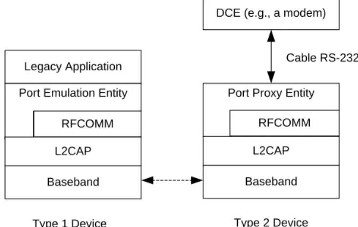
7.1 Port Emulation and Port Proxy Entities
This section defines how the RFCOMM protocol should be used to emulate serial ports.
Figure 7.1 shows the two device types that the RFCOMM protocol supports.
Type 1 Device Type 2 Device DCE (e.g., a modem)
Port Emulation Entity Legacy Application
RFCOMM
L2CAP
Baseband
Port Proxy Entity
RFCOMM
L2CAP
Baseband
Cable RS-232
Figure 7.1: The RFCOMM communication model
Type 1 devices are communication endpoints such as computers and printers. Type 2 devices are part of a communication segment; e.g., modems.
7.1.1 Port Emulation Entity
The port emulation entitymaps a system specific communication interface (API) to the RFCOMM services.
7.1.2 Port Proxy Entity
The port proxy entityrelays data from RFCOMM to an external RS-232 interface linked to a DCE. The communications parameters of the RS-232 interface are set according to
received RPN commands; see section 5.5.1.
7.2 Service Registration and Discovery
Registration of individual applications or services, along with the information needed to reach those (i.e., the RFCOMM Server Channel) is the responsibility of each application respectively (or possibly a Bluetooth configuration application acting on behalf of legacy applications not directly aware of Bluetooth).
Below is a template/example for developing service recordsfor a given service or profile using RFCOMM. It illustrates the inclusion of the ServiceClassList with a single service class, and a ProtocolDescriptorList with two protocols (although there may be more protocols on top of RFCOMM). The example shows the use of one other universal attribute (ServiceName). For each service running on top of RFCOMM, appropriate
SDP-defined universal attributes and/or service-specific attributes will apply. For additional information on Service Records, see the SDP Specification [3], Section 2.2. The attributes that a client application needs (at a minimum) to connect to a service on top of RFCOMM are the ServiceClassIDList and the ProtocolDescriptorList
(corresponding to the shaded rows in the following table).
Item Definition Type/Size Value Attribute ID
ServiceClassIDList Note1 0x0001
ServiceClass0 Note5 UUID/32-bit Note1
ProtocolDescriptorList 0x0004
Protocol0 L2CAP UUID/32-bit L2CAP
/Note1
Protocol1 RFCOMM UUID/32-bit RFCOMM
/Note1
ProtocolSpecificParameter0 Server
Channel
Uint8 N = server
channel #
[other protocols] UUID/32-bit Note1
[other protocol-specific parameters]
Note3 Note3 Note3
ServiceName Displayable text name DataElement/ String ’Example service’ Note2
[other universal attributes as appropriate for this service]
Note4 Note4 Note4 Note4
[service-specific attributes] Note3 Note3 Note3 Note3
Notes:
Defined in “Bluetooth Assigned Numbers” [4]
1. For national language support for all ’displayable’ text string attributes, an offset has to be added to the LanguageBaseAttributeIDList value for the selected language (see the SDP Specification, Section 5.1.14 for details).
2. To be defined (where necessary) for the specific service.
3. For a specific service some of the SDP-defined universal attributes may apply. See the SDP Specification, Section 5.1
4. This indicates the class of service. It may be a single entry or a list of service classes ranging from generic to most specific.
7.3 Lower Layer Dependencies
7.3.1 Reliability
RFCOMM uses the services of L2CAP to establish L2CAP channels to RFCOMM
entities on other devices. An L2CAP channelis used for the RFCOMM/TS 07.10
multiplexersession. On such a channel, the GSM 07.10 frames listed in section 4.2 are sent, with the adaptation defined in section 5.1.
Some frame types (SABM and DISC) as well as UIH frames with multiplexer control commands sent on DLCI 0 always require a response from the remote entity, so they are acknowledged on the RFCOMM level (but not retransmitted in the absence of acknowledgment; see section 5.3). Data frames do not require any response in the RFCOMM protocol, and are thus unacknowledged.
Therefore, RFCOMM shall configure L2CAP to provide channels with reliability, to provide assurance that all frames are delivered in order, and without duplicates. To achieve that, the L2CAP error control mechanism may be used or the flush timeout must be configured to be infinite.
7.3.2 Low Power Modes
If all L2CAP channels towards a certain device are idle for a certain amount of time, a decision may be made to put that device in a low power mode (i.e., use hold, sniff, or park, see ‘Baseband Specification’ section 10.10.3). This will be done without any
interference from RFCOMM. RFCOMM may state its latency requirementsto
L2CAP.This information may be used by lower layers to decide which low power mode(s) to use.
The RFCOMM protocol does not suffer from latency delays incurred by low power modes, and consequentially, this specification does not state any maximum latency requirement on RFCOMM’s behalf. Latency sensitivity inherently depends on application requirements, which suggests that an RFCOMM service interface
implementation could include a way for applications to state latency requirements, to be aggregated and conveyed to L2CAP by the RFCOMM implementation. (That is if such procedures make sense for a particular platform.)
8
References
[1] GSM 07.10, v6.3.0, ETSI
[2] Bluetooth Core Specification v2.0 + EDR and later, Volume 3, Part A (L2CAP) [3] Bluetooth Core Specification v2.0 + EDR and later, Volume 3, Part B (SDP)
9
Terms and Abbreviations
The following terms are used throughout the document.
Term
Definition
DTE Data Terminal Equipment – in serial communications, DTE refers to a
device at the endpoint of the communications path; typically a computer or terminal
DCE Data Circuit-Terminating Equipment – in serial communications, DCE
refers to a device between the communication endpoints whose sole task is to facilitate the communications process; typically a modem RFCOMM
initiator
The device initiating the RFCOMM session; i.e. setting up RFCOMM channel on L2CAP and starting RFCOMM multiplexing with the SABM command frame on DLCI 0 (zero)
RFCOMM Client An RFCOMM client is an application that requests a connection to another application (RFCOMM server)
RFCOMM Server An RFCOMM server is an application that awaits a connection from an RFCOMM client on another device. What happens after such a
connection is established is not within the scope of this definition RFCOMM Server
Channel
This is a subfield of the GSM 07.10 DLCI number. This abstraction is used to allow both server and client applications to reside on both sides of an RFCOMM session