Enhancement of Power Quality by Using Shunt Hybrid Power Filter
With TCR
D. Srikanth
1, V. Sreepriya
2 1M. Tech scholar, Department of EEE, S.R Engineering College, Warangal, T.S, India
2Assistant Professor, Department of EEE, S.R Engineering College, Warangal, T.S, India
Abstract:-
This paper presents a thyristor-controlled reactor (TCR) in combination with a fifth-tuned LC passive filter and active power filter (APF) in order to compensate the reactive power and to reduce harmonics.In addition, it reduces significantly the volt-ampere rating of the APF part. The shunt hybrid power filter (SHPF) is the combined system of a small-rating APF connected in series with a fifth-tuned LC passive filter. A control scheme based on proportional-integral controller has been used to mitigate the harmonics and reactive power.The proposed system also helps in achieving a low cost highly effective control.Keywords- Power Quality, harmonics, shunt hybrid
power filter, thyristor-controlled reactor, reactive power.
I. INTRODUCTION
Now a day’s power electronic equipment’s are
mostly used in industrial and domestic purpose. This
equipment’s have majorimpact on the quality of supply voltage and have increased the harmonic current content of distribution systems. They have many negative effects on distribution system side equipment’s
and customer, such as additional losses in overhead and underground cables, transformers and rotating electric machines, problem in the operation of the protection systems, over voltage and shunt capacitor, error of measuring instruments, and malfunction of low efficiency of customer sensitive loads.The most important power quality problems are harmonics and high neutral current.The definition of power quality given in the IEEE dictionary originates in IEEE Std1100: Power quality is the concept of powering and grounding sensitive equipment in a manner that is suitable to the operation of that equipment. Power quality problems are common in most of commercial and industrial networks. Natural phenomena, such as lightning are the most frequent cause of power quality problems.Also, the connection of high power non-linear loads contributes to the generation of current and voltage harmonic content the major and critical power
factor to consider in order satisfying good productivity. On the other hand, for the electrical supply industry, the quality of power delivered will be one of the distinguishing factors for ensuring customer loyalty in this very competitive and deregulated market. Reactive power, Power factor, Harmonic distortion and Voltage unbalance in power supply are the major problems of power quality. According to IEEE-519, total harmonics distortion is defined as the summation of the effective value of the harmonics components in the distorted waveform relative to the fundamental component.
Passive filter have been used traditionally for minimizing the distortion due to harmonic current in industrial power systems. But they have many drawbacks such as resonance problem, dependency of their performance on the system impedance, absorption of harmonic current of nonlinear load, which could lead to further harmonic propagation through the power system [2].To overcome those problems active power filters is introduced. It has no such drawbacks like passive filter. They inject harmonic voltage or current with appropriate magnitudes and phase angle into the system and cancel harmonics of nonlinear loads [9]. But it has also some drawbacks like high initial cost and high power losses due to which it limits there wide application, especially with high power rating system [3].
at high-powerlevels, which is cost-effective because of the kilovoltampererating reduction of the inverters. A hybrid consists of a three-phase three-level neutral pointclamped (NPC) inverter and a series connection of a three-levelH-bridge inverter with a novel control scheme to control thefloating voltage source of the H-bridge stage has been introduced in [10]. In this topology, the NPC inverter is used to supplythe total active power while the H-bridges operate as seriesactive filters for the harmoniccompensation of the NPC outputvoltage. The rating of the series active filter is reduced becauseit provides only the reactive power for the operationof the floating capacitor.Different control techniques are present for extracting harmonic components of the source current. Some of them are synchronous reference frame (SRF) transformation, instantaneous power (p-q) theory, etc. where high pass filters (HPF) are used or extracting harmonic components of the source current from the fundamental components [6].
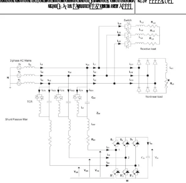
The proposed combination of SHPF and TCR is as shown Fig. 1 which compensates the reactive power and reduces harmonic currents. In addition, it reduces significantly the volt-ampere rating of the APF part. The SHPF consists of a small-rating APF connected in series with a fifth-tuned LCpassive filter. The APF consists of a three-phase full-bridge voltage-source pulse width modulation (PWM) inverter with an inductor (L ,R ) and a dc bus capacitor (C ). The APF sustains very low fundamental voltages and currents of the power grid, and thus, its rated capacity is greatly reduced.Considering the above mentioned merits, the presented combined topology is very appropriate in compensating reactive power and eliminating harmonic currents in power system. The tuned passive filter in parallel with TCR forms a shunt passive filter (SPF). This latter is mainly for fifth harmonic compensation and power factor correction. The small-rating APF is used to mitigate the harmonics generated by the load and the TCR by enhancing the compensation characteristics of the SPF aside from eliminating the risk of resonance between the grid and the SPF. The TCR goal is to obtain a regulation of reactive power.The simulation results are listed in comparison of different control strategies and for the verification of results.
II. MODELING AND CONTROL OF
SHPF
A. Modeling of SHPF
The system equations are first elaborated in 123
reference frame. Using Kirchhoff’s voltage law, one
can write
V = L didt + R i + V + V + V V
= L didt + R i + V + V + V
V = L didt + R i + V + V + V V
= L didt − C L d Vdt V
= L didt − C L d Vdt V
= L didt − C L d Vdt ddt
= 1 i (1)
The switching functionC of thek leg of the converter (for k = 1, 2, 3) is defined as
C = 1 if s is on and s is off0 if s is off and s is on (2)
A switching state functiond is defined as
= { −13 ( )} (3)
Moreover, the absence of the zero sequence in the ac currents and voltages and in the [d ] functions leads to the following transformed model in the three-phase coordinates
L didt = −R i − d v − v + v
L didt = −R i − d v − v + v
L didt = −R i − d v − v + v
C + = d i + d i + d i (4)
However, the model is time invariant during a given switching state. Furthermore, the principle of operation of the SHPF requires that the three state variables have to be controlled independently. The interaction between the inner current loop and the outer dc bus voltage loop can be avoided by adequately separating their respective dynamics. Since the steady state fundamental components are sinusoidal, the system is transformed into the d-q reference frame at constant supply frequency. The conversion matrix is
=
cos cos − cos −
Fig. 1 Basic Circuit of SHPF-TCR Compensator
Whereθ = ωtand the following equalities hold: Cdq123
= (C123dq)−1= (C123dq)T.
Then, by applying dqtransformation, the state space model of the system in the synchronous reference frame is obtained.
B. Controlling of Harmonic Current
A nonlinear control of SHPF is developed for current tracking and voltage regulation purposes. It is based on a decoupled control strategy, which considers that the controlled system may be divided into an inner fast loop and an outer slow dc voltage loop, is adopted. Note that the first and the second time derivative TCR capacitor voltages have no significant negative impact on the performance of the proposed control technique because their coefficients are too low. Consequently, they can practically be ignored.
By using the d-q transformation, the decoupled dynamics of the current tracking is obtained. The currents iand i can be controlled independently.
state errors can be achieved. The expressions of the tracking controllers are
u = L 1 − C L ω + L didt + R 1 − C L ω i = k i + k i dt
u = L 1 − C L ω + L didt + R 1 − C L ω i
= k i + k i dt (6)
Where i = i*d− idand i = i*q− i are current
errors and i*dand i*qdenote the reference signals of
idandi respectively.
The transfer function of the proportional–
integral controllers is given as
G (s) = U (s)
i (s) = k + k
Fig. 2 Inner Control Loop of the Current id
The inner control loop of the current idis
shown in Fig. 2. The closed-loop transfer functions of the current loops are
I (s) I∗(s) =
k A
s +
s + s + k
I (s) I∗(s) =
k A
s +
s + s + k (8)
Where A = L (1 − CPFLT ω2) + LTand B =
R (1−CPFLTω 2
).
The closed-loop transfer functions of the current loops have the following form
I (s) I∗(s) = 2ζω
s +
s + 2ζω s + ω (9)
whereω is the outer loop natural angular frequency
and ζisthe damping factor. For the optimal value of the damping factor ζ =√2/2, the theoretical overshoot is 20.79%. The following design relations can be derived
k = k = 2ζ L 1 − C L ω + L
− R 1 − C L ω
k = k = L 1 − C L ω + L ω (10)
Note that the inputs q and q consist of a nonlinearity cancellation part and a linear decoupling compensation part.
C. DC Bus Voltage Regulation
The active filter produces a fundamental voltage which is in-phase with fundamental leading current of the passive filter. A small amount of active power is formed due to the leading current and fundamental voltage of the passive filter and it delivers to the dc capacitor. Therefore, the electrical quantity adjusted by the dc-voltage controller is consequently. The outer control loop of dc bus voltage is as shown in Fig. 3. To maintain equal to its reference value, the losses through the active filters resistive-inductive branches will be compensated by acting on the supply
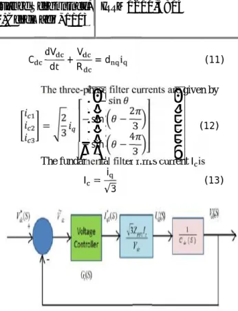
C dVdt +R = d iV (11)
The three-phase filter currents are given by
= 2
3 ⎣ ⎢ ⎢ ⎢
⎡ − sin − sin −23
− sin −43 ⎦⎥ ⎥ ⎥ ⎤
(12)
The fundamental filter r.m.s currentI is
I = i
√3 (13)
Fig. 3 outer control loop of the dc bus voltage
The q-axis active filter voltage is expressed as
V = q V = −Z i∗ (14)
Where ZPF1is the impedance of the passive filter at 60
Hz and i*q1is a dc component.
u = q i (15)
The control effort of the dc voltage loop is deduced
i∗ = V
−Z i u (16)
The dc component will force the SHPF-TCR compensator to generate or to draw a current at the fundamental frequency.
To regulate the dc voltageV the errorV = V*dc− V ispassed through a PI-type controller given
by
u = k V + k V dt (17)
The response of the dc bus voltage loop is a second-order transfer function and has the following form:
V (s) V∗(s) = 2ζω
s +
s + 2ζω s + ω (18)
V (s) V∗ (s) =
√
s +√
s +√ s +√ (19)
Where V is the average value of dc voltage which isequal to 50volts.The proportional k and k integral gains are then obtained as follows:
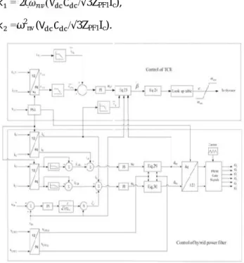
k = 2ζ (V C /√3ZPF1Ic),
k =ω2nv(V C /√3ZPF1Ic).
Fig. 4 Schematic diagram of SHPF and TCR controller
By designing the dc bus voltage loop much slower than the current one, there would not be any interaction between the two loops. The controller of the proposed SHPF and TCR system is as shown in Fig. 4. The system parameters are given in Table I.
TABLE I: SYSTEM PARAMETERS
Line to Line source
voltage and frequency V = 208 V,f = 60 Hz Line impedance L = 0.5 mH,R = 0.1Ω
Nonlinear load L = 10 mH,R = 27Ω Linear load L = 20 mH,R = 27Ω Passive filter parameters L = 1.2 mH,C = 240μF
Active filter parameters C = 3000μF,R = 1 kΩ DC bus voltage of APF of
SHPF V = 50 V
Switching frequency 1920 Hz
Inner controller parameters K = K = 43.38
K = K = 37408
Outer controller parameter K = 0.26,K = 42 Cut off frequency of the
low pass filters F = 70 Hz
III. MODELING AND EXTRACTION OF
FIRING ANGLE OF TCR
TCR equivalent circuit is as shown in Fig. 5.
Using Kirchhoff’s voltage law, the following equations
in 123 reference frame are obtained
V = L didt + ddt + R i + d V
V = L didt + ddt + R i + d V
V = L + + R i + d V (20)
Fig. 5 TCR equivalent circuit
Applying Park’s transformation to above equation we
get
L (∝)didt = L (∝)ωi + L ωi − L didt − R i − d V + V
L (∝) = −L (∝)ωi − L ωi − L −
R i − d V + V (21)
The reactive part is chosen to control the reactive current so thatV = 0 and LT(α)ωi = 0
= B(∝)ω −L ωi − L − R i − dnqVdc(22)
Where B (α) = 1/L (∝)ωis the susceptance. An equivalent inputu is defined as
u = (23)
According to this expression, one deduces
B(α) = u
ω −L ωi − L − R i − d V (24)
On the other hand, the equivalent inductance is given by
L (∝) = L π
2π − 2 ∝ + sin(2 ∝) (25)
Fig.6. Susceptance versus firing angle.
Fig.6. illustrates the susceptance versus firing angle. A PI controller is used to force the reactive current of the SHPF-TCR compensator to follow exactly the reactive current consumed by the load.
IV. SIMULATION MODEL AND
RESULTS
Simulations were performed numerically using
the “Power System Block set” simulator operating
under MATLAB/Simulink environment, in order to verify the operation of the proposed SHPF-TCR compensator using the nonlinear control scheme.
Fig.7 Simulink model of proposed SHPF and TCR combination for power quality enhancement
Fig.8 TCR controller
Fig.9 Hybrid power filter controller
Fig.7, Fig.8, Fig.9, are the Simulink model of SHPF – TCR compensator, TCR controller and controller of hybrid power filter respectively.Here simulation is carried out in several cases, in that 1). Proposed Hybrid Power Filter with Steady State Harmonic Generated Load. 2) Transient State Harmonic Load and 3) Transient State Harmonic and Reactive Power Generated Load.
Fig.10Source Voltage, Source Current, Load Current, Compensation Current, DC Link Voltage.
Fig.10 shows the Steady State Response of Source Voltage, Source Current, Load Current, Compensation Current and DC Link Voltage of the SHPF-TCR Compensator on Harmonic Generation Load.
Fig.11FFT Analysis of Source Current
Fig.11shows FFT Analysis of Source Current of the SHPF-TCR Compensator on Harmonic Generation Load, attains THD as 0.90%.
2) Transient State Response of the System for Harmonic Generated Load
Fig.12 Source Voltage, Source Current, Load Current, Compensation Current, DC Link Voltage
Fig.12 shows the Transient Response of Source Voltage, Source Current, Load Current, Compensation Current and DC Link Voltage of the SHPF-TCR Compensator on Harmonic Generation Load.
3) Transient State Response of the System for Harmonic and Reactive Power Generated Load
Fig.13 Source Voltage, Source Current, Harmonic Load Current, Compensation Current, DC Link Voltage and
Reactive Load Current
Fig.14FFT Analysis of Source Current
V. CONCLUSION
In this paper a SHPF – TCR compensator is proposed in order to suppress the current harmonics and reactive power compensation generated by the load. In addition, it reduces significantly the volt-ampere rating of the APF part. The control circuit for the SHPF and the TCR are also explained. A control technique is proposed to improve the dynamic response and decrease the steady-state error of the TCR. The output of the system for various conditions had been explained with the help of the simulation results. The performances of the SHPF – TCR compensator for steady state and transient state of various harmonic and reactive loads are found to be effectively eliminated the current harmonics and reactive power compensation. It has been shown that the system has a fast dynamic response, has good performance in both steady-state and transient operations, and is able to reduce the THD of supply currents.
REFERENCES
[1] E. F. Fuchs and M. A. S. Masoum, "Power Quality in Electrical Machines and PowerSystems," Academic Press, USA, 2008.
[2] J. C. Das, "Passive filters; potentialities and
limitations,” IEEE Trans. on IndustryApplications, Vol.
40, pp. 232- 241, 2004.
[3] B. Singh, K. Al-Haddad, and A. Chandra, “A review of active filters for power qualityimprovement,” IEEE
Trans. Ind. Electron., vol. 46, no. 5,pp. 960–971, Oct. 1999.
[4] L. Asiminoaei, E. Aeloiza, P. N. Enjeti, and F. B
laabjerg, “Shunt active-power- filtertopology based on
parallel interleved inverters,” IEEE Trans.Ind. Electron.
vol. 55, no.3, pp. 1175–1189, Mar. 2008.
[5] H. Fujita, H. Akagi, "A practical approach to harmonic compensation in power systems;series connection of passive and active filters," IEEE Trans.
[6] L. Asiminoaei, E. Aeloiza, P. N. Enjeti, and F. B
laabjerg, “Shunt active-power- filtertopology based on
parallel interleaved inverters,” IEEE Trans.Ind.
Electron. vol. 55, no.3, pp. 1175–1189, Mar. 2008. [7]B. Singh, V. Verma, A. Chandra, K. Al-Haddad, "Hybrid filters for power qualityimprovement," IEEE Proc. on Generation, Transmission and Distribution, Vol. 152,pp. 365-378, 2005.
[8] Salem Rahmani, AbdelhamidHamadi,
NassarMendalek, and Kamal Al-Haddad, “A New Control Technique for Three-Phase Shunt Hybrid
Power Filter,” IEEETransactions on industrial electronics, vol. 56, no. 8,pp. 606-805, august 2009. [9] M. I. Milanés-Montero, E. Romero-Cadaval, and F. Barrero-González,“Hybrid multiconverter conditioner topology for high-power applications,”IEEE Trans. Ind. Electron., vol. 58, no. 6, pp. 2283–2292,Jun. 2011. [10] C. A. Silva, L. A. Cordova, P. Lezana, and L.
Empringham, “Implementationand control of a hybrid
multilevel converter with floating dc linksfor current
waveform improvement,” IEEE Trans. Ind. Electron.,
vol. 58,no. 6, pp. 2304–2312, Jun. 2011.
[11] A. Luo, S. Peng, C. Wu, J. Wu, and Z. Shuai,
“Power electronic hybridsystem for load balancing
compensation and frequency-selective
harmonicsuppression,”IEEE Trans. Ind. Electron., vol.
59, no. 2, pp. 723–732, Feb. 2012.
[12] A. Luo, Z. Shuai, W. Zhu, and Z. John Shen,
“Combined system forharmonic suppression and reactive power compensation,” IEEE Trans.Ind. Electron., vol. 56, no. 2, pp. 418–428, Feb. 2009.
DADI SRIKANTH currently pursuing his M.Tech in
Power Electronics from S.R Engineering College (Autonomous), Warangal, Telangana, India, affiliated to JNTU, Hyderabad. He has done his B.Tech degree from S.V.S Institute of Technology, affiliated to JNTU, Hyderabad, Telangana, India and his fields of interest include Power Systems.
V. SREEPRIYA received her B.Tech degree in