Accredited by RISTEKDIKTI, Decree No: 32a/E/KPT/2017 doi: 10.14203/jet.v18.60-66
Binary Template Matching for Morphological Dilation
Enhancement in Navigation Radar Imaging
Octa Heriana
*, Teguh Praludi, Chaeriah Bin Ali Wael
Pusat Penelitian Elektronika dan Telekomunikasi Lembaga Ilmu Pengetahuan Indonesia Komplek LIPI Gd 20, Jl Sangkuriang 21/54D,
Bandung 40135, Indonesia
Abstract
Radar imaging system is strongly influenced by other supporting systems. There is a motor system that provides angular information to the display system, and Digital Signal Processing (DSP) system that provides the main information for radar imaging. The new approach, we substitute a DC servo motor with a DC stepper motor as radar antenna rotator in our navigation radar system development. Different from the use of servo motors that can provide angle movements smoothly, the new motor system provides angle information of 0.56 degrees in every step, results in empty pixel gaps in every 0.56 degrees in radar Plan Position Indicator (PPI) image. The width of the empty pixel gaps becomes wider when the cell array of raw data is increasing regarding the image plotting process. In this paper, we proposed a new morphological dilation method to the radar raw data based on binary template matching to accommodate the various width of empty pixel gaps before the radar raw data are plotted into the radar PPI image. By this method, the morphological dilation will only be applied to the raw data that meet the same criteria as the binary template. Otherwise, the raw data will be left as they are. The result shows that there is 150.52% pixel data addition in the empty pixel gaps from the original image, and 48.44% increase of the morphological dilation without binary template matching method.
Keywords: radar imaging, raw data, binary template matching, dilation.
I. INTRODUCTION
Radar antenna motor system that was used previously in navigation radar developed by P2ET-LIPI is a continuous DC servo motor. The continuous DC servo motors require high current when it is run, have large dimensions and heavyweight. In the further development, we substituted the servo motor with stepper motors that aim to be more economical and to reduce the dimensions and weight of the radar. A new problem is found, the change in the motor system causes the movement of the rotating angle of the antenna motor to become unsmooth. The angle movement is 0.9 degrees when the stepper motor is operated in half step mode and 1.8 degrees when it is operated in full step mode [1].
The ratio of the gearbox used in radar motor system using stepper motor produces a movement angle of 0.9:1.12. The radar raw data generated from DSP is sent 2 times in one step of stepper motor movement, there are at the beginning and at the middle of the movement. The middle angle is half of the width of the gear box's output angle, which is 1.12/2. Thus the raw data will be sent every 0.56 degrees. With a condition of 0.56 degrees angle width and 512 cell raw data, the results of raw data plotting into the Plan Position Indicator (PPI) display will obtain empty gaps. The width of the empty pixel gap becomes greater when each cell array of raw data increase in distance.
A study presented in [2] found that gaps in the radar display image would appear if the coordinate computation process of raw data position in the image was carried out too long. With the application of look-up tables for determining image coordinate data, these empty gap can be significantly overcome. This study found that problem which is able to bring the empty gaps is not only the computational time problem but also the angle obtained by the motor system. An image processing technique, morphological dilation is used to improve the image quality that has some deformities of line gaps in the image caused by the change of image contour [3]. The morphological dilation is carried out uniformly in each pixel of the image so that the entire edge of the pixel image will be added with some additional pixels. In this study the empty gaps found were almost all uniforms, and the image that did not have gaps would appear to be wider because the pixel data addition is evenly distributed on all edges of each image pixel. This method will not be optimal to be applied if the empty gaps are varied because it will need more than 1 element structure if the size of gaps to change larger when the cell array of raw data distance farther away. Morphological dilation method can only fill the empty pixels based on the structure elements matrix initial size. The larger the size of the matrix, the wider the outer side of the pixel addition. The almost similar morphological dilation method has been carried out in previous studies to improve the less visible radar PPI display image [4]. In this study, the motor system used is quite different. The DC servo motor used in the previous research can provide smoother angular
* Corresponding Author.
Email: [email protected]
Received: October 24, 2018 ; Revised: November 21, 2018 Accepted: November 06, 2018 ; Published: December 31, 2018
2018 PPET - LIPI
information than the use of stepper DC motor applied in this research.
A template matching algorithm is usually used to find out the geometric properties of unknown image data [5]. This method is used to search coordinate data positions in images [6] in the process of merging multiple disconnected images [7], or processing letter recognition on digital documents [8], and processing other image data by offline or real-time in terms of computer vision technology development [9]. Other studies developed a search for the closest similarity using effective correlation to match templates to the data which are tested [10],[11]. By applying a binary template matching, the dilation process will only be applied to the raw data that meet the same criteria as the template. The number of pixels added will correspond to the area of the empty gaps so that only the edges of the images that have the empty gaps will be dilated, while images that do not have gaps will be ignored.
In this paper, we proposed a method to accommodate the morphological dilation to the images that have various width of empty pixel gaps. In this method, the morphological dilation is performed to the radar raw data before radar image data are plotted based on the use of binary template matching. The main function of binary template matching is to search the raw data properties obtained by radar DSP system based on their binary values for data preprocessing. By implementing this method, the various width of empty gaps could be filled more, better than the use of morphological dilation method performed in the previous research [4].
The problem of this study is explained in section I. Section II introduces the concept of the method. In section III, the implementation of the method is explained. The result of the method implementation is described in section IV. Section V is the conclusion of this paper.
II. SYSTEM DESIGN
The changes to the motor system used in the developed radar system resulted in an angular movement of 0.56 degrees. This angle is large enough to create empty gaps when the raw data is plotted on the radar PPI display. The large empty gap occurred is shown in Figure 1, with the height of the empty gaps can be calculated through the calculation of the sine-triangle value (1).
𝑆𝑖𝑛 𝜃 =ℎ
𝑛, (1)
where is the angular gap between first raw data transmission and the second transmission, h is the height of gap in the pixel, and n is the length of raw data.
Based on (1), the empty gaps that appear on the process of representing the radar raw data into the PPI display will increase as the process of raw data plotting from raw data cell 1 to 512. The cell array of 2 raw data from 1 to 205 has a gap of 1 cell which is equivalent to 1-pixel width. The cell array of raw data from 206 to 307, there is 2 cells gap, or equivalent to 2 pixels width.
Then in the cell array of raw data from 308 to 409, there is a gap of 3 cells or 3 pixels width, and the gap of 4 cells or 4 pixels width is found in the cell array of raw data from 410 to 512. Illustration of the gaps appeared between 2 raw data are shown in Figure 2-5.
The binary template matching for morphological dilation method developed in our study is shown in Figure 6. This method is quite different from a method used in our previous study [4] which is shown in Figure 7.
Figure 1. The height of the empty gap between 2 raw data
Figure 2. 1 pixel gap between2 raw data from cell array 1 to 205
Figure 3. 2 pixels gap between2 raw data from cell array 206 to 307
Figure 4. 3 pixels gap between 2 raw data from cell array 308 to 409
Figure 6. Diagram block of morphological dilation based on binary template matching of radar raw data.
Figure 7. Diagram block of morphological dilation of radar image used in previous research.
In the previous study, there were only a few narrow empty gaps occurred in raw data plotting process to radar PPI display due to the leakage of the computational process. To overcome that problem, we performed a common morphological dilation process which is shown in an expression in (2) with a 2x2 element structure matrix. The morphological dilation was run after radar image data are plotted in 1 full rotation. With this method, all image pixels are calculated with the specified structure element matrix.
𝐺(𝑗, 𝑘) = 𝐹(𝑗, 𝑘) ⊕ 𝐻(𝑗, 𝑘), (2)
where G(j,k) is a dilated image, F(j,k) is the original binary-valued image, and H(j,k) is a binary valued structuring element used in morphological dilation [12]. The dilation of F by H is the set that consists of the reflected and translated the result of structure element H that overlaps at least 1 binary valued “1” of the original image F. The structure element used in this purpose is a 2x2 structure element matrix of H (3);
𝐻 = [1 1
1 1] (3)
The binary template matching for morphological dilation method developed in our study is shown in Figure 7. The process is started by creating a 2x2 of 16 template matrices that represent binary values from 0000 to 1111. Then, image properties of raw data pairs obtained by DSP based on binary template matching are checked. In the next step, the raw data pairs are scanned from cell to 1 to 512. Then, if the raw data pairs meet the template criteria, raw data dilation will be performed by the number of data and the patterns that have been determined based on the template. The final step is to plot all the optimized raw data into the PPI radar display image.
A. Binary Template Matching and Raw Data Dilation
Template matching is one of the simplest and most basic methods in detecting objects in an image by comparing the replica of an object that is interesting to an unknown object in the image data. If the comparison result has a very close match, then the compared object will be labelled as a template object [12]. The basic template matching operation is by sequentially scanning
over the image data to be compared and to find the similarity.
The template matching method used in this research is pixel level template matching, the total templates model is chosen which has the same size as the input data, without rotation or translation. This method will be used to identify which patterns will be used in the addition of binary data to gaps in the raw data obtained by the DSP. The template matching process is implemented after 2 raw data are collected. The templates are designed in 2x2 matrix data so that it requires at least 2 lines of 512 cells array of raw data to be compared.
The raw data to be displayed on the PPI display has an array length of 512 cells. The length of the raw data, when plotted into the PPI display image is the length of the radius of PPI display which is adjusted to the general size of the monitor screen used.
The binary template matching algorithm described in the following steps:
1) Read the motor angle
2) Input 2 sets of raw data from DSP into 2 variable
array with sizes of 512 cells.
3) Calculate the 2x2 raw data matrix starting from
the 152 cell of raw data array based on the template sequence, explained more detail in the next chapter.
4) Compare and perform raw data dilation
operations:
The raw data cell from 152 to 205 refer to the
pattern in table I.
The raw data cell from 206 to 307 refer to the
pattern in table II.
The raw data cell from 308 s.d. 409 refer to
the pattern in table III.
The raw data cell from 410 s.d. 512 refer to
the pattern in table IV.
5) Plot raw data on the pixel of PPI display.
6) Go to the next second array cell,
cell= cell + 2.
7) Check if the array cell has occupied 511, if not,
returned to step i).
8) Check whether the angle> 360 degrees, if yes, do
image dilation, if not, return to step 1).
B. Image Plotting
Image plotting is applied to compile the raw data of the template matching result into the PPI images. This process is done by arranging all raw data from the center coordinate of the PPI display towards the outer pixel as long as the radius of the PPI display circle. The steps can be described as follows:
1) Read the motor angle data.
2) Determine the center coordinate of the PPI image,
which is the location of the pixel (x, y) on the display.
3) For the cell of raw data (i) from 1 to 512,
X = Cx+ (i ∗ (Cx∗0.95)
512 ) ∗ sin (
∗π
180)), (4)
Y = Cy+ (i ∗ (Cy∗0.95)
512 ) ∗ cos (
∗π
180)), (5)
where X and Y are coordinates of the pixel in x
and y-axis, Cx and Cy are the center coordinates of
PPI plane in x and y-axis, and is 0.56 degrees,
the angular of the gap between 2 raw data.
4) After x and y pixel coordinate values are obtained,
plot the color value data on the pixels (x, y).
5) Return to step 1) until one full rotation (360
degrees).
III. DESIGN IMPLEMENTATION
Figure 8 is the template used to determine the dilation pattern. Templates are compared to input data in the form of binary values from 2x512 cell array of raw data. The template is 2x2matrix, so the process of comparing templates to input data is by reading the 2x2 raw data from the 1st cell array of raw data then it is shifted every 2 cells to the cell position to 511.
The gap of 1 pixel appeared in the image data that has been plotted on the PPI display is considered not to be repaired, because the lack of 1 pixel does not affect the appearance of the PPI display and it can still be ignored by human vision. Therefore the template matching process is started from the cell array of 152.
Raw data from cell array 152 to 205 follows the pattern I, with the addition of data as much as 2x2 pixels data. The raw data from cell array 206 to 307 follows pattern II, with the addition of 3x2 pixels data. For raw data from cell array 308 to 409 follow pattern III, with the addition of data as much as 4x2 pixels and raw data from cell array 410 to 512 follow the pattern IV, with the addition of data as much as 5x2 pixels data.
The following Figure 9-12 are the dilated patterns matrices for 2 pixels, 3 pixels, 4 pixels, and 5 pixels gaps according to the template sequence in the previous Figure 8.
Based on the 2x2 template matrices as shown in Figure 8, the templates can be represented as some indexes, which are an index of 0 to 15. Each index has pattern information based on a gap of 2 pixels to 5 pixels. Index and pattern information can be arranged into a look-up table as shown in Table 1. The pattern I show that each index consists of 4bits binary row, meaning that in each index, 4 pixels will be inserted between the two raw data. Pattern II consists of 6 bits of binary data so that each index in this pattern will be added as much as 6 pixels of data. Pattern III has an arrangement of 8bits binary data patterns and pattern IV has a 10bits binary data pattern arrangement, and all of them will fill the empty pixels as much as the binary data length they have.
Figure 8. 2x2 template matrices.
Figure 9. Dilation patterns for 2 pixels gap.
Figure 10. Dilation patterns for 3 pixels gap.
Figure 11. Dilation patterns for 4 pixels gap.
TABLE 1.
INDEX AND BINARY PATTERN OF TEMPLATES
In
d
e
x Binary Pattern
I II III IV
0 0000 000000 00000000 0000000000
1 0001 000001 00000101 0000000101
2 0010 000010 00001010 0000001010
3 0011 000011 00001111 0000001111
4 0100 010000 01010000 0101000000
5 0101 010101 01010101 0101010101
6 0110 011110 01011010 0101111010
7 0111 011111 01011111 0101111111
8 1000 100000 10100000 1010000000
9 1001 101101 10100101 1010110101
10 1010 101010 10101010 1010101010
11 1011 101111 10101111 1010111111
12 1100 110000 11110000 1111000000
13 1101 111101 11110101 1111110101
14 1110 111110 11111010 1111111010
15 1111 111111 11111111 1111111111
To evaluate the performance of morphological dilation based on binary template matching, we measured the Mean Opinion Score (MOS) value of image data when they were plotted in the form of original images, images dilated without binary template matching, and images dilated with binary template matching. The MOS values were measured based on the clarity and empty gaps reduction level of plotted radar image data. The clearer radar image data are plotted, the higher MOS value they have.
The other performance evaluation method of this study was by measuring the quantity of pixel addition of radar PPI images obtained by morphological dilation without binary template matching, and the radar PPI images obtained by morphological dilation using binary template matching from their original images. This evaluation can be simply done by counting the total of pixels containing data from the images obtained by morphological dilation without or with binary template matching, and they are compared with the original images.
IV. EXPERIMENTAL RESULT
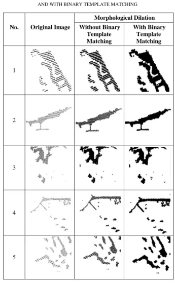
The process of observing the implementation of the proposed method is done randomly. Displayed in Figure 13, there are 5 different observation locations were taken to see the difference before and after being processed with the previous method and the proposed method. As explained in the introduction section, the
results of radar imaging with a distance of 0.56 degrees of raw data transmission can be seen that the farther the cell array distance of the raw data displayed, the more gap of the image representation from the two raw data will be seen. This occurrence can be seen in the first column image in Table 2, the original image.
The results of image enhancement using morphological dilation without binary template matching of original images with a 2x2 structure element can be seen in the second column of Table 2. Although it appears that the several gaps of the pixels have been filled in, but there are still clearly visible that the large gap between 2 raw data could not be filled in perfectly.
The test results from the method proposed in this study can be seen in the third column of Table 2. Through the initial processing of raw data based on the suitability of the template, the gaps between the 2 raw data can be covered perfectly based on the patterns arranged in the look-up table, so that the image of the object appears to be fully filled without empty gaps.
The Mean Opinion Score value measurement results are shown in Figure 14. In average, the images with binary template matching for image 1-5 in Table 2 reached the highest value of MOS, 4.8, while the original image represented MOS value of 2.2 and the dilated image without binary template matching represented MOS value of 3.84. Therefore the use of binary template matching for morphological dilation of radar raw data performed better result than the use of common morphological dilation of plotted radar image data in reducing the empty gaps in radar PPI display plotting process.
From the observation, the quantity of pixel addition on the empty pixel of the original image by morphological dilation without binary template matching is 102.08%. The radar PPI display result is shown in Figure 15. By using binary template matching morphological dilation, the raw data addition factor on the empty pixel of the original image is 150.52%. The radar PPI display result of this implementation is shown in Figure 16.
Figure 14. MOS values of the original image, image dilation without binary template matching, and with binary template matching
Figure 15. PPI Display after morphological dilation without binary template matching
Figure 16. PPI display after morphological dilation with binary template matching
TABLE 2.
COMPARISON OF THE ORIGINAL IMAGE, IMAGE AFTER MORPHOLOGICAL DILATION WITHOUT BINARY TEMPLATE MATCHING,
AND WITH BINARY TEMPLATE MATCHING
No. Original Image
Morphological Dilation Without Binary
Template Matching
With Binary Template Matching
1
2
3
4
5
V. CONCLUSION
The change of the mechanical system of the radar motor system results in changes in the mechanism of reading angular data and changes in raw data transmission time. This has an effect on radar image processing, causes the results of image plotting on PPI display to have some empty gaps in every 0.56 degrees. Through the addition of a preprocessing method with binary template matching dilation on DSP radar raw data in cell array from 152 to 512, the empty gaps can be fixed. There are 4 different patterns applied to each raw data range. Adding data in the cell array of raw data from 152 to 205 by 2 pixels, raw data from cell array 206 to 307 by 3 pixels, raw data from cell array 308 to 409 by 4 pixels and raw data from cell array 410 to 512 by 5 pixels. The improvement of radar PPI image plotting quality can be seen from the pixel addition number in the empty pixels from the original image. There is 150.52% for the morphological dilation with binary template matching method and increased by 48.44% from the morphological dilation without binary template matching method.
ACKNOWLEDGEMENT
We would like to thank the members of Electronics System and Signal Processing Research Group at the
Telecommunication, Indonesian Institute of Sciences (P2ET). This research activity is financially supported by DIPA project in partly Indonesian Institute of Sciences (LIPI) with the title “Development of Navigation Radar System using ARM Single Board Computer”.
REFERENCES
[1] T. E. Kissell, Industrial Electronics: Applications for Programmable Controllers, Instrumentation & Process Control, and Electrical Machines & Motor, 2nded., US: Prentice Hall,
1999.
[2] L.Baiping, L. Dan, “Research and realization of coordinate conversion in radar video display,” in Proc. 2013 Ninth Int. Conf. Computational Intell. Security, 2013, pp. 277-279. [3] P. Liu, et al., "Research on the Graphic Correction Technology
Based on Morphological Dilation and Form Function QR Codes," in Proc. 2016 Int. Conf. Network Inform. Syst. Comput. (ICNISC), 2016, pp. 323-327.
[4] A. N. Rahman, O. Heriana, P. Putranto, F. Darwis, E. J. Pristianto, and Y. N. Wijayanto, “Morphological dilation for radar image enhancement,” in Proc. 2017 Int. Conf. Radar, Antenna, Microwave, Electron. Telecommun. (ICRAMET), 2017, pp. 68-71.
[5] R. M. Dufour, E. L. Miller, and N. P. Galatsanos, “Template matching based object recognition with unknown geometric parameters,” IEEE Trans. Image Process., vol. 11, no. 12, pp. 1385–1396, Dec. 2002.
[6] W. Hu and B. Wang, “A template matching algorithm for high precision positioning,” in Proc. 2017 8th IEEE Int. Conf. Software Eng. Service Sci. (ICSESS), 2017, pp. 704-707. [7] B. Wang, Z. Wei, Z. Li, W. Hu, S. Wang, S. Zhang, C. Du, and
W. Shi, “Region-based template matching method for multi-view coastline image stitching,” in Proc 2017 8th IEEE Int. Conf. Software Eng. Service Sci. (ICSESS), 2017, pp. 680-683. [8] V. S and S. A, “Template Matching Technique for Searching
Words in Document Images,” Int. J. Cybernetics Informatics, vol. 4, no. 6, pp. 25–35, Dec. 2015.
[9] C. H. Quach, V. L. Tran, D. H. Nguyen, V. T. Nguyen, M. T. Pham, and M. D. Phung, “Real-time lane marker detection using template matching with RGB-D camera,” in Proc.2018 2nd Int. Conf. Recent Advances Signal Process. Telecommun. Computing (SigTelCom), 2018, pp. 152-157.
[10] E. A. Kuzu and A. Tangel, “Correlation template matching CPA method,” Electron. Lett., vol. 52, no. 15, pp. 1306–1308, Jul. 2016.
[11] P. Sandhya, V. Naidu, “Real Time Object Visual Inspection Based on Template Matching using FPGA,” Int. J. Eng. Trends Technology (IJETT), vol. 4, no. 8, pp. 3521–3526, Aug 2013. [12] William K Pratt, Digital Image Processing, 3rd ed., New York,