Appendix
G. General Practice for Installing and Use of
Settlement Plates
Background
Earth materials generally compress an observable amount when load is applied. Soils, in particular, when subject to load, may deflect, consolidate, or densify. Fill materials and native soils may react immediately, slowly, or very slowly, to loadings depending on the type of material and the effect of water on the soil system. The magnitude and rate of compression [or deflection] is often difficult to predict, particularly in cohesive, fine grained, soils such as silt and clay. Deformations in a soil system may be elastic or plastic in nature, or a combination of both.
Sands (coarse grained)
Sandy soils typically display immediate settlement characteristics. These soils consolidate very quickly (the time may vary from nearly instantaneous to several days). Often sands are assumed to have elastic properties and an associated value of material stiffness. Settlement is not generally monitored where a site consists of exclusively sandy (granular) materials. The total strain for a given applied stress is often very small (a few percent), consequently overall deflections are also small.
Clays (fine grained, cohesive)
Clayey soils exhibit consolidation behavior which is fairly well understood, though complex. Stress history, mineralogy, age, moisture content, and geologic formation all play a role in the strength and behavior of clay materials. Generally, clays exhibit a roughly bi-linear behavior pattern. Clays respond to applied stress with relatively low strains until the maximum past pressure is applied, after this point, they tend to respond to increased load at a greatly increased rate of strain. The time rate of consolidation of clay materials is highly dependent on particle sizes of the soil and drainage paths. Thick deposits of high clay content materials may take years to consolidate, even under high stress. Soils with greater silt content, or possessing favorable free drainage conditions (such as sand seams), may consolidate relatively rapidly.
Organic Materials
Organic soils are generally treated as a distinct material category as they contain relatively large amounts of,or exclusively, non-soil materials. Organic materials are subject to decay processes where the material chemically and structurally changes over time. This decay can have profound effects on the strength and behavior properties of the material. Organic soils are typically very dark in color, have very low dry unit weights, and have high moisture contents. Moisture contents in organic material may range from 30% to over 1000%. Texture may range
from very fibrous to fluid muck. Typically, organic materials have very large strains associated with any loading condition in excess of the in-situ stress. Large stresses in high moisture peat deposits may result in strains well in excess of 50%. Overall behavior is highly site specific. Consolidation behavior in organic materials is also less uniform as compared to mineral soils, sudden compression ‘events’ can occur where local changes in structure result in sudden deformations even at constant stress.
For all geomaterials, behavior is dependent on the site geometry (layer thicknesses) and location of the water table, applied loading (stress) conditions, and material properties, such as density, permeability, overconsolidation ratio (OCR), and water content.
General Use
The most common settlement monitoring system is the settlement plate. These instruments may be simply constructed and read manually, or involve relatively complex fluid and electrical sensor systems for remote reading and automated recording. Settlement plates are typically installed in areas where significant settlement is predicted.
They can be used to examine if predicted settlement: 1) is occurring
2) is occurring at predicted rates and magnitudes
3) has occurred to a magnitude of interest (or over a time of interest) 4) is substantially complete
5) is not occurring
Settlement plates may also be installed to monitor heave, either caused by material displacement or frost. Settlement plates may be used alone or in conjunction with other instrumentation including horizontal inclinometers, piezometers, borehole extensometers, and hydraulic remotely-monitored settlement systems.
Construction
Typical settlement plate construction is outlined in the included diagram. The base platform is typically made of plywood but may also be a steel plate or concrete pad. A reference rod (riser pipe), with threaded end connections, is attached to the platform. As fill is placed over the settlement plate additional segments of pipe are added.
Note that where high quality readings of the behavior at the plate elevation are of interest, and/or where extra protection is required, a PVC protection pipe should also be placed around the threaded riser pipe. The plastic pipe should be of sufficient diameter to accommodate any couplers used to connect the riser rods.
Settlement plates may be placed at any given elevation of interest. Typically they are installed on the existing ground surface prior to the construction of embankment fill. They may also be
placed in excavations, at reinforcing interfaces, or within embankments to monitor settlement characteristics.
Settlement is determined by periodically measuring the elevation of the top of the reference rod. The elevation of the base platform elevation must be measured before the embankment construction begins. Subsequent readings should be taken periodically during the embankment construction and whenever additional riser pipes are attached.
Stable benchmarks should be used for a reference elevation datum and should be located away from all possible vertical movement or other disturbance. Depending on the importance of the installations it may be necessary to use multiple benchmarks for redundancy and survey elevations between them at regular intervals for validation.
The Foundations Unit generally recommends the use of settlement plates where soil settlements have been predicted to be of a large (or undeterminable) magnitude, and could cause construction or operational difficulties to roadways or structures.
Other units within Mn/DOT may specify the use of settlement plates if there is concern with respect to roadway or structural performance due to poor or unknown soil conditions.
Bridge Abutment Foundations (Piling)
Bridge Abutment Foundations (Spread Footings) Bridge Approach Embankments
Embankments
Waiting periods, if specified, should be adhered to. Failure to postpone construction until after consolidation settlement has been allowed to occur at problematic sites can result in significant construction difficulties, structural damage, delays, reconstruction, and associated incurred costs.
Waiting Periods
Settlement plates are frequently used where a “waiting period” for construction has been recommended. Waiting periods are a minimum specified time to allow consolidation settlement to occur, generally after fills over soft or compressible soils or large fills have been placed. Waiting periods are determined from predictions based on the geotechnical site investigation and associated testing and analysis.
Waiting periods are used to prevent pavement distress, differential settlement of hydraulic structures, curbing, wingwalls, or other structures, and to prevent ‘pile dragload.’ Pile dragload is a condition where compressible soils in or below the fill layer adhere to structural piling and impart an additional downward acting load into the pile as the soils consolidate, possibly overstressing it. Additionally, if the piling is not founded on a firm layer, settlements in the piling may be excessive due to the added load and reduced area of resisting soil support.
Monitoring of the actual ground behavior, with settlement plates, can be used to determine if work may begin in advance of the minimum waiting period time. It should also be noted that if settlement is excessive, the waiting period may be extended.
Site Plan and Location Selection
Settlement plates should be located such that construction traffic in the vicinity is minimized if at all possible. Plate installations and riser pipes should be clearly and adequately marked to
protect the riser pipes from impact or obliteration during fill placement, grading, and other construction activities that will be ongoing during the monitoring process.
Note also that the bench-mark (or fixed reference elevation) used to survey the settlement plates must also remain intact through the monitoring process. A stadia rod may be used to obtain the fill elevation if the top of fill is not visible from the survey point; both the elevation of the riser pipe and the top of fill should be surveyed for use in settlement data analysis.
Installation
Settlement plates should be installed prior to any addition of fill material. Refer to the installation diagram [Figure 3-2.10, Mn/DOT Geotechnical and Pavement Manual, Part 1, April 1, 1994]. Ground elevation and the elevation of the settlement plate riser pipe should be established and recorded prior to placement of the fill material to establish a baseline reading.
The plates should then be monitored regularly through the fill placement process and the following waiting period to determine the total soil movements, some of which occur during the fill placement process. It is important that the plates be surveyed immediately at the time of installation.
For a typical bridge, consisting of two abutments, two settlement plates are installed. Note that settlement plates are generally not required at bridge piers, as there is usually a minimum of fill at these locations. A greater number of settlement plates may be warranted if fills are large in either height or lateral extent, if there is risk that they will destroyed by construction traffic, or for redundancy if the site is of particular importance.
Settlement plates should be installed slightly below grade as in Figure 3-2.10, Mn/DOT Geotechnical and Pavement Manual, Part 1, April 1, 1994. Care should be taken in installing the plates, reading elevations, and extending riser pipes.
Survey Data
The riser pipe should be surveyed to a fixed datum or bench mark well outside the embankment fill area. The height of fill should also be surveyed and recorded at each monitoring interval. It is important that original installation data and subsequent monitoring data be clearly recorded for each settlement plate installation. Added sections of riser pipe, and their lengths, should be clearly noted in the data log.
It is important to install and read them correctly to verify that settlement. As settlements are relatively small, surveys should be conducted to the greatest accuracy reasonably obtainable under field conditions. In general, GPS systems are not accurate or precise enough in the “z” axis (height) to be used for settlement plate data acquisition.
Monitoring Intervals (Data Collection Reading Frequency)
It is essential that the settlement plates be surveyed as soon as they are placed.
During initial construction of the fill and any time thereafter when fill is being actively placed, the settlement plates should be read every two to three days.
After the fill placement has been completed, the plates may [generally] be read weekly. When fill is being placed, the amount of fill (lift heights) should be recorded for use in settlement data interpretation.
Any extreme or unusual events should also be recorded, such as rainstorms, local flooding, or seismic activity (either natural or nearby blasting). If the plates are damaged and/or repaired or relocated, this should also be noted.
All settlement data should be sent to the Foundations Unit for review and interpretation. Refer to the section on transmitting data at the top of the following page.
It is preferred that the same surveyors read the settlement plates over the course of the monitoring period to reduce the opportunity for error. Project data and elevation readings should be reported in appropriate units (either in U.S. Customary Units or SI units, depending on the project).
The location of the plates should be surveyed at the time of installation and include Roadway Station and Offset and either Latitude and Longitude or UTM coordinates (X,Y), as well as the elevation. The survey reference system should be indicated.
If there are a large number of plates on a particular project, it is also important that they be clearly named/numbered to ensure that there is no confusion in the data recorded for each installation.
Some projects may require a more frequent or specific interval for reading, depending on the criticality of the project. Staged embankment fills over soft soils may require especially frequent monitoring.
Transmitting Data
Data may be submitted to the Foundations Unit electronically, via fax, or through the mail. Electronic data transfer is preferred as errors are somewhat less likely. If information is mailed or faxed, it is important that the information be legible. Data should be clearly labeled with the State Project number, Highway or Site, Bridge or Structure # (if applicable) Plate # (if applicable), Location (i.e. east or west abutment) and Roadway Station/Offset, Date, Elevation of the Top of Fill, and Riser Pipe Elevation. Added lengths of riser pipe should also be indicated, as appropriate.
The foundations unit direct fax number is 651-779-5510. Electronic mail addresses are available for each project engineer in the unit.
Please contact the Foundations Engineer, Gary Person, at PH: 651.366.5598, e-mail:
[email protected] for the engineer assigned for a specific project.
Analysis
The Foundations Unit will interpret the data and associated settlement behavior. If the behavior is such that construction may proceed in advance of any given waiting periods or is such that construction should be postponed, the appropriate offices will be notified.
Data Interpretation
Impact on Waiting Periods
Waiting periods are determined on a case by case basis after a geotechnical review of the site. The installation of settlement plates does not necessarily ensure a reduction in the waiting period duration. The Foundations Unit will assess the data from the settlement plates to determine if the soil consolidation is substantially complete or at such a stage where the majority of the predicted settlement has occurred.
Figures G-1 through G-4Samples of Settlement Plate Graphs with Common Errors
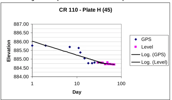
Figure G-1- Some elevations were shot with GPS and others using a level. GPS elevations are generally of insufficient precision for resolving the small movements
anticipated at most sites.
CR 110 - Plate H (45)
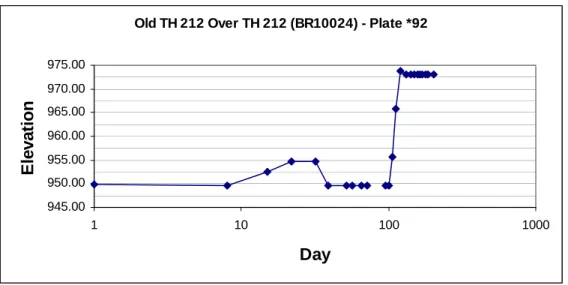
884.00 884.50 885.00 885.50 886.00 886.50 887.00 1 10 100 Day E levat io n GPS Level Log. (GPS) Log. (Level)Figure G-2- The height of additional sections of rods were probably not recorded and subtracted out from the measurements associated with this settlement plate.
Figure G-3- This graph shows the relatively large scatter associated with the GPS data points as compared to those shot with a level. Additionally, the readings should have
been taken more frequently earlier Old TH 212 Over TH 212 (BR10024) - Plate *92
945.00 950.00 955.00 960.00 965.00 970.00 975.00 1 10 100 1000 Day E le vat io n
Pedestrian Trail Over TH 212 - Plate 59
927.00 927.25 927.50 927.75 928.00 1 10 100 Day E levat io n GPS HTPO Level Log. (GPS)
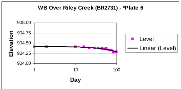
Figure G-4This graph is the best of those presented above (Figures 1-4) and shows anticipated behavior (monotonically decreasing plate elevation).
Sample of Well Organized Settlement Plate Table
Figure G-5 (page 11, at the end of the document [landscape]). This table shows settlement plate data to an appropriate precision for multiple plates. The information is clearly presented (plates are labeled with stationing and lifts dates and reading dates are included along the vertical axis).
Special Cases
In general, the reading schedules and installation instructions herein, and as shown in Figure 3-2.10, on page 3- 2.0(38) in the Mn/DOT Geotechnical and Pavement Manual, apply.
If there are modifications to these standards they will be included in the project plans and special provisions. Depending on the performance and behavior of the settlement plates, modifications to the reading frequency may be made by the project engineer.
Alternate Methods and Related Equipment
Some critical installations, locations with confined working areas, or areas at or near structures may require the use of buried, piezometers, settlement cells, horizontal inclinometers, or accelerometer arrays. These systems can be combined with traditional settlement plates or
WB Over Riley Creek (BR2731) - *Plate 6
904.00 904.25 904.50 904.75 905.00 1 10 100
Day
E
levat
io
n
Level
Linear (Level)
used on their own where the use of settlement plates is impractical or the data quality is especially important to the project.
Piezometers may be used to monitor the dissipation of excess pore water pressure that is induced by embankment loading on cohesive (non-free-draining) materials. These instruments do not measure settlement directly, but they can be used to determine the rate of consolidation and if any pore-water overpressure exists, which are useful in assessing whether soil movements are complete for a given loading stage. Several types exist; vibrating-wire type are recommended.
Settlement cells usually employ a piezometer system to determine changes in elevation based on changes in pressure in a system with a fixed reference frame. Typically, a settlement cell will be referenced to a fixed fluid reservoir (either installed in a fixed stratum in a boring or at a fixed location offset a horizontal distance from the area of interest). The down-side of these types of sensors is that they are sensitive to installation damage, temperature, and generally require a specialty contractor to install, set-up, calibrate, and read/maintain. The benefit is that there are no poles to interfere with construction operations (or traffic) at the top of the loaded/instrumented area.
Horizontal inclinometers, as the name implies, are slope inclinometer casings installed parallel to the ground, usually through an embankment. These systems use a specialty probe that senses deflections in the casing as it is passed through the system. The system requires a return-pulley at one end, if the casing does not pass fully through the embankment. This system is relatively easy to install and can sense relatively small changes in deflection. The system must be referenced at either (or both) end(s) to a fixed datum or extended to a distance where movement is not occurring to ensure that readings are accurate.
Similar to a horizontal inclinometer, an accelerometer array is a linear element placed within the area of interest for settlement monitoring. These systems employ a string of accelerometers that are left in-place and connected to a data acquisition system for periodic automated reading. The accelerometers record shifts in the orientation of the array with respect to gravity. This system also requires a fixed (or referenced) datum. The benefits of this system are the relatively robust performance of the array, the precision (generally movements as small as 2 mm can be resolved) the automated data collection. These systems, are however, usually comparatively expensive and therefore recommended mostly for long-term performance monitoring of structures, research, or critical applications. If the array is not strained to failure, the sensors can usually be pulled and re-used, which decreases the project cost considerably- and in some instances a savings over traditional horizontal inclinometers could be realized through labor and travel cost reductions (particularly if the site is not conveniently located).
Note that some portions of all the above systems are sacrificial and cannot be recovered. Installation and monitoring should be performed by geotechnical engineers who are familiar with construction instrumentation.
For additional Information:
Please contact the Mn/DOT Foundations Unit for any clarification or questions.
Reference: Figure 3-2.10