SLAC-PUB-6152 May 1993
(A)
The Final Focus Test Beam Laser Reference System*
V.E.Bressler, R.E.Ruland
Stanford Linear Accelerator Center, Stanford University, Stanford, CA 94309 U.S.A.
Abstract A precision hinge which enables the zone plate to
return to the same position with each actuation is The original design for the SLAC linac required; only one zone plate may be lowered into included an alignment reference system with 270 the light at one time.
An inexpensive CCD camera with an array of diffraction gratings situated along the 3000 meter
size 8x6mm is used. FFTB images are much linac. These gratings have provided SLAC with a
global reference line repeatable to within 200 larger than this CCD array. Therefore the camera micro meters. For the Final Focus Test Beam, this must be moved many times in order to detect one FFTB image[li. The accuracy of the camera laser system has been extended and 13 new
diffraction gratings have been installed, positioning system is approximately 10 micro Improvements in the image detection system, in meters. However, FFTB images have high the calibration of the targets and the availability of sensitivity, figure 2, and need only be detected to new instruments allows us to evaluate the withintcns or hundreds of micro meters in order to performance of the laser reference system at the 5- achieve alignment information at the zone plat_=
10 micro meter level. An explanation of the with precision of a few micro meters.R: D_ance from S: Distance from Zone Plate system and the results of our evaluation are lasertoZonePtate lolmagefocalpoint
presented. = u=_. 0._
zone plate J
1. INTRODUCTION
_
[_,_
Components of the FFTB laser alignment [s-,a_v= Motloooftl'_image
I
system are illustrated in figure 1. A 1 mW HeNe ] 'Motionoftt_zoneplate= --_ ] imageMOti°n°fthe
laser provides images with peak intensity of
Figure 2. Definition of sensitivity.
approximately 1 lux at the detector. (Note that ali FFTB zone plates are less than 150 m from the
laser). The divergent lens is chosen such that the 2. IMAGE MEASUREMENTS intensity of light at the edges of the zone plate is
about 75% of the intensity of light at the center of "!i iii !i!!iii!i! iliii _ii i i iiii the zone plate. _-"_...iii' ::i_...H"__jI! '!_' '_i...i...ii__ ':... ::::_::
r_,,_ z,,, r_, _t_'"ii::"! ... ;'i.... i... ::" ';i
Aclu..to¢ Mechanism o ... '
_'0 N . . : : : " , .
=.,
og
ii
ii
il
!i
_ I_
iii
• l ... '"": ' ':" """ ""' "l'':" ;'""':": .... t ... "":":
noon " ' noon
Sun 12/12/92 noon Mon Tue
0:00 (200 13:.O0
2 hours per div
[ Fmer_ Zone Plate Figure 3a. Measurement of FF-I'B LSX1 Ftesnelzone plate image.
Designed f_r this location. VERTICAL LSXI: r = 162.8 m, s = 3284.7 m, N = 20
: ,_1 350Om
Figure1a.ComponentsoftheFFTBlaseralignmentsystem. '...!...!...:...
llux- _._ i i , i S_. i ...
controled
camera o:_o 2 hours per dlv
posilioner, midnight
Figure 3b. Measurement of FFTB LSX1 Fresnel zone plate image. (HORIZONTAL) Figurelb. ComponentsoftheFFTBlaseralignmentsystem.
*Worksupportedbylhc U.S.DepartmentofEnergyundercontractl)E-AC03-76SF00515 M_iiT" __[.,,,_._ Contributed Zothe Particle Accelerator Conference (PAC'93) Washington DC, May 17-20 1993
_;:S-.-;"-,<r__!TI£24M0_ TI-{i_ D,O(.;UMENT t16UNL ,._.
t
I
Three days of data from the FFTB laser These imperfections are stable; cross sections alignment system are show in figure 3. This data laken on different days contain the same was produced by lowering a single zone plate and imperfections.
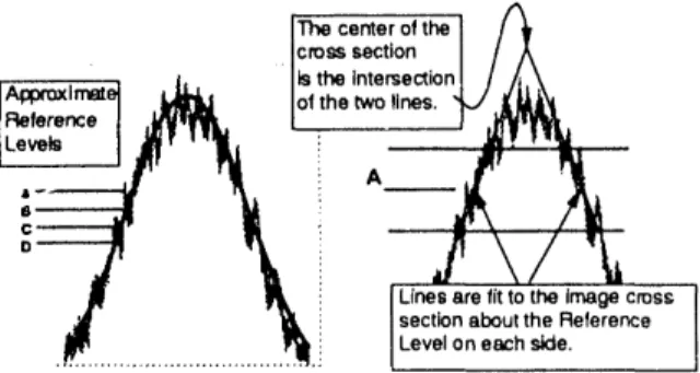
repeatedly measuring the image from this zone Looking at figure 4, one might wonder if the plate. M:)tions indicated by the data are a computed center of such an image is a good combination of motions of the zone plate, the measurement of the center of the "ideal" image. camera and the laser. Motions of the camera and Figure 5 illustrates the image detection algorithm.
the laser may be eliminated when a set of three or By varying the Reference Level and more different images are monitored. However remeasuring the center of the image, one may gain that was not done in this case. The data from a sense of how well we are computing the center of figure 3 is useful in order to evaluate the standard the ideal image.
deviation or quality of the measurements made by
the image detection system. The standard The centerofthe //_
cross section A
deviation of these measurements, computed in . i. ltsthelntersectionl k\
terms of the position of the zone plate, is less than IApl_xirr_el.lleli_IReference| ,wl_rf_ Ioithetwollnes.I _J I(tlii'_l_r_,
5gm. ILev°* / ,w, "I=, ! ,,,: "_
• i A
3. ACCURACY OF IMAGES :" _ _ _ \ / '_a
Figure 3 illustrates the repeatability of the: j. I_, i I Linesarefitt° the imagecr°sS
measurement of zone plate images. However, this ._ ilk i JsectionabouttheRelerence data says nothing about the accuracy ,of these .._... .._..i JLeveloneachside.
measurements. Notice that the standard deviation Figure 5.Quickexplanation oftheimage detection algorithm. of the vertical measurements is less than the
standard deviation of the horizontal measurements. The data from _gure 6 is taken directly The algorithm which is used to detect the center of from the database which is attached to the image the image uses (1) the vertical cross section of the detection program. This data consists of 12 image to compute the vertical coordinate of the different measurements of the center of the LSX7 centr'r of the image and (2) the horizonltal cross image at 4 different reference levels. X and Y are section of the image to compute the horizontal the horizontal and vertical coordinate of the image coordinate of the center of the image, in inches as measured in the coordinate system of
the image detector. Etime is the time required for ]IdealintonsityJ the algorithm to converge in seconds. Center Amp
Icross section r,,
_--,ntor_iW
I"°m
I_ _'l°riz° a-Td' determines the effective reference level.of Isimulation. J_ I_1_.
detectedlaser i
r
-i
DI,,
rx-
,celt _. =0Co.n^32-7 -X-0._11q0.2413 I99212/0914:14 TRANS 3_- ii"3.0 32-7"_B J-0.6174 -0.2425 1992 1730914:21 TRANS 130 113.0 light 324 e32.7J -0.6154-0.6342 -0.2414-0.2425 1992 lz/oe 14;241992 1730914:30 TRANSTRANS 208150 113.0100.0 32-7_ C -0.6358 -0.2432 1992 1730914:36 TRANS 273 100.0 32-7 -0.60_) -0.2434 1892 12/09 14:43 TRANS 334 100.0 32-7E -0.6289 -0.2426 1992 12/09 14:48 TRANS 222 85,00 32-7_ I -0.6258 -0.245,5 1992 12/09 14:56 TRANS 288 85.00 •_---"-'--_ q _ 32-7E I -0.6171 -0.2450 1992 1730915:00 TRANS 169 85.00
3 inches (75 mm) 3 inches (75 mm) 32-7 i -0.9187 -0.2283 1992 1730915:05 TRANS 268 130.0
32-7 A ] -0.8236 -0.2305 1992 12/09 15:09 TRANS 148 130.0 Figure 4. Image intensity cross sections. 32-r -O,61_ -O.2380 1902 12./0915:12 TRANS 151 130.O
(FFTB FresnelTargetLSX7) 12/00/92 Figure 6. Image measurements at different reference levels.
Therefore if the standard deviation of the The total range of ali the Y (vertical) computed vertical coordinate of the image is less measurements is 440_m and 840Frm for the X than the standard deviation of the computed (horizontal) measurements. Translating these horizontal coordinate of the image, we would
measurements into distance at the zone plate we expect that the vertical cross section of the image have: Vertical Range: 5.6gm Horizontal Range: would be of better quality than the horizontal cross
section of the image. Figure 4 illustrates that this 2.9Wn. As far as the image detection algorithm is
is indeedtrue, concerned, these images are quite symmetric.
The imperfection in the images shown in Therefore when we compute the center of the figure 4 are caused primarily by stray light, "imperfect" image, we are computing the position ... • r¢fl.ected off the interior of the vacuum enclosure.
of the center of the zone plate to within about (02)HowprecJ_e_ musttheslotsofazone plate befabricated? 5_tm. Simulations conducled for the FFTB LSX7 (r=22.9 m, s=3424.5 m,
N=20) Fresnel zone plate. The simulated zone plate has been given random asymmetric imoerfeclions with standard deviation A
6, IMAGE SIMULATIONS and the center of the resullant image has then been computed.
Prior to the construction of the FFTB laser ._.1sum....r"!; ..._"_...;!": ...:_ ..._r: ...__;
alignment systemweinvestigatedthefeasibilityof _+lou,, _ i i " i ! ! i :j-."! -'!'!'i' i i i
.... !...L..i ... _ ... _..._ .-I-.'-..-! ... i...i...i ...
a Fresnel zone plate laser alignment system with 5 _um _ i _i- " | i i i i i :: i i ! i l,tm accuracy. Several of the questions on our : ° - ii-i-.| i i j I":.-_._..._".!il...i...ili...i[i mind were: (Q1) How precisely must the slots of a _ -s_ ... ...ii "..i i'ii! zone plate be fabricated? (Q2)How large must a _._o_ ...i...!...i...!...i..."=:i2i '' zone plate be? (Q3) Does the angle of the zone .,_r, -i._i_.6;_.-._ ..._._ ...2oo_:.... plate with respect to the incident light wave i_ii(Fresrlelz°neplatesl°tvanatl°n)
matter? (Q4) What happens when light from the
laser is not symmetrically distributed across the (o3)Does the angle of the zone plate with respect to
the incidentIght wave matter?
surface of the zone plate? 0
In order to answer these questions we By workingthroughthemathematics
Incident
conducted one and two dimensional simulations light \ ofoursimulationalgorithms wefound
which assumed (1) Light incident on the zone plate ) that this angle 0 does not significantly has a gaussian intensity profile and has spherical effect the image produced by thisplate for values of 0 less than severalzone phase, originating at the laser. (2) The zone plate is degrees.
located at distance R from the laser. (3) The zone
plate may move horizontally or vertically with Tangent lineto incidentlight
spherical wave.
respect to the laser line. (4) The zone plate may
pitch or yaw with respect to the laser line. (5) The (Q4) What happens when light from the laser is not
camera is located distance S from the zone plate, symmetricalydistributedacrossthesurfaceofthezone plate?
Available space does not permit a description Gaussian
of the simulation algorithm, therefore we will beamGaussian 64widthmm km.
simply present results, intensityprofile _1t LSX7 zOne plate__ _ssian offset
(Q1) How large must a zone plate be. centered on aolive area
the zone 48 mm wide
By "large" I really mean, what is the required number of slots in the plate. zone pla_e? This is an important issue sinoe _ the slots become
small, manufacture of the zone plate becomes incre_ingly difficult Gaussian offset Image offset and expensive. The number of slot3 in the zone plate is given by the 5 mm 3.9 um order of the zone plat_, N.
10 mm 7.0 um
==ii mi,,, F'rom the figure ] 20 mm 13.5 um
iii thai ali those extra / CONCLUSION:
slots past N:12 [ Fresnel zone plate alignment systems can
... ":'"i ... !""__ don't greatly |"
... !"i ...i_.,l..._i_]iiiii_enhanoethe 1"" provide alignment information with relative !... i_ ... :.,_lV-.."-I ... overall width or /"
Id_image i'i ...I::_/,/A#<_-..'.:.._IIII sha,pne,_oft_ I accuracy from zone plate to zone plate of 5 lxm
crosssections ::'"'i... i" __'i-_ --'! image. / without expensive image detection hardware and
,o, ano ,
....
val_osofN. 'i4=1_P-_7'-; ..."_'.] ... with zone plates fabricated to 5 txm tolerances.
_;i"itS ... ":: ... ' ... '...
(FFTBI_XST) __" iii !!i ii""..:'i!i.... "..""i!'''i!......-."_--"iiii_ .x3_i_ FFTB Fresnel zone plate alignmentbeen shown to be, (1) Symmetric to within 5 lxmimages have
loomm - (2) Re-measurable to within 5 l.tm.
References
[1 ] V.E.Bressler,G.E.Fischer,R.E.Ruland,T.Wang, "High Resolution Fresnel Zone Plate Laser Alignment System", EPAC'92 Conference Proceedings Vol.2 (March 1992), pp. 1613-1615