The handle
http://hdl.handle.net/1887/26519
holds various files of this Leiden University
dissertation.
Author: Zheng, Sipeng
Mononuclear spin-transition materials
based on the bapbpy scaffold
PROEFSCHRIFT
ter verkrijging van
de graad van Doctor aan de Universiteit Leiden,
op gezag van Rector Magnificus Prof. mr. C.J.J.M Stolker,
volgens besluit van het College voor Promoties
te verdedigen op woensdag 25 juni 2014
klokke 11:15 uur
door
Sipeng Zheng
geboren te Beijing, China
Samenstelling Promotiecommissie
Promotor
Prof. Dr. E. Bouwman
Co-promotor
Dr. S. Bonnet
Overige leden
Prof. Dr. J. Brouwer
Prof. Dr. J.A. Real (Universitat de València)
Prof. Dr. J. Reedijk
Prof. Dr. J.M. van Ruitenbeek
List of abbreviations... 5
Chapter 1 Introduction... 7
Chapter 2 Increasing the transition temperature of bapbpy-based mononuclear spin-crossover compounds: interplay between molecular and crystal engineering……….. 29
Chapter 3 Effect of metal dilution on the thermal spin transition of [FexZn1−x(bapbpy)(NCS)2]……….. 57
Chapter 4 Influence of selenocyanate ligands on the transition temperature and cooperativity of bapbpy-based Fe(II) spin-crossover compounds... 81
Chapter 5 Synthesis and magnetic properties of bapphen-based mononuclear iron(II) spin-crossover complexes... 109
Chapter 6 High-temperature cooperative spin crossover of an iron(II) amine-bridged bis-bipyridine complex... 131
Chapter 7 Synthesis, magnetic properties, and STM imaging of an iron(II) bapphen complex functionalized with a long alkyl chain………... 145
Chapter 8 Conclusions and outlook………...……….. 169
AI Supplementary information on Chapter 3... 179
AII Supplementary information on Chapter 4... 183
AIII Supplementary information on Chapter 5... 187
AIV Supplementary information on Chapter 6... 191
AV Supplementary information on Chapter 7... 197
Samenvatting... 203
List of Publications... 209
List of abbreviations
bapbpy N,N’-di(pyrid-2-yl)-2,2’-bipyridine-6,6’-diamine bapphen N,N’-bis(pyrid-2-yl)-1,10-phenanthroline-2,9-diamine
bbpya N,N-bis(2,2’-bipyrid-6-yl)amine
BINAP 2,2'-bis(diphenylphosphanyl)-1,1'-binaphthyl
bpy 2,2’‐bipyridine
d, dd, m, s, t Doublet, doublet of doublet, multiplet, singlet, triplet (in NMR spectra)
DCM Dichloromethane
DMF N,N-Dimethylformamide
DMSO Dimethyl sulfoxide
DSC Differential Scanning Calorimetry
EA Elemental analysis
eq equivalent
ESI-MS electron spray ionization mass spectrometry
HR-MS high resolution mass spectrometry
HS, LS High spin, low spin
ICP-OES Inductively coupled plasma optical emission spectrometry
IR Infrared
LFS Ligand field splitting
LIESST Light-induced excited spin state trapping
NMR nuclear magnetic resonance
phen 1,10-phenanthroline
ppm parts per million
PXRD Powder X-ray diffraction
r.t. room temperature
SCO Spin Crossover
SQUID Superconducting quantum inteference device
STM Scanning tunneling microscopy
TMS Tetramethylsilane
1
Introduction
In computing and digital communication, a bit (short for binary digit) is the basic unit of information. The scientific and technological developments in the last sixty years have allowed for reducing the bit size from 250 μm to 22 nm following the so-called “top-down” approach.1, 2 However, this approach is reaching its limits both in terms of size (e.g.,
lithography is limited by diffraction),3 and in terms of investments/price, as it becomes
more and more expensive to manufacture such small systems. The bottom-up approach appears as an attractive alternative, as it is based on the idea that the smallest unit capable of performing information storage and data treatment is one molecule.4 The first advantage
of molecular electronics is quantitative: molecules are ~1 nm in size, which represents a serious improvement in terms of information density and processing speed. But there is another qualitative advantage: individual molecules are not simply smaller than a collection of molecules, they also behave differently, i.e., according to quantum physics. This might completely change the way information is stored and treated in future computers. In order to store information a molecule needs to behave as a switch, i.e., to exist at least in two different states. One type of candidates for molecular switch comprises spin-crossover (SCO) complexes.5 In this Chapter, a general introduction to the subject of SCO is given, as
1.1
General background of spin crossover and ligand field theory
When Cambi and Szegö first described (1931) the thermal spin crossover (SCO) of disubstituted dithiocarbamate iron(III) compounds,6 little was known about this
phenomenon. After several decades of continuous developments, the field of spin crossover research has greatly expanded, and the SCO phenomenon is recognized as one of the most fascinating phenomena in inorganic chemistry.7
In an octahedral or distorted octahedral geometry, first-row transition metals with d4-d7
electronic configurations can adopt either a high-spin (HS) or a low-spin (LS) electronic configuration, depending on the crystal field splitting introduced by the ligands (Figure 1.1). When the HS and LS states are close in energy the metal ion can switch between these two states by external perturbations such as temperature variations,8 light irradiation,9-11 or by the application of pressure,12-14 of a magnetic
field,15 or of an electric field.16 In thermal SCO the LS state is populated at low
temperatures, whereas the HS state becomes the most stable state at higher temperatures.
To date, iron(II) is certainly the metal ion for which the largest number of SCO compounds has been reported.7 Iron(II) has d6 electronic configuration, the SCO
converts the 1A
1 LS state into the 5T2 HS state (Figure 1.1). Apart from Fe(II),
examples for Co(III),17 Co(II),18, 19 Fe(III),20, 21 Ni(II),22 and a few cases of Cr(II) and
Mn(III)23 are reported in the literature. However, in the cases of Co(III) and Fe(III) the
stronger ligand field splitting and weaker interelectronic repulsion energy makes them less favourable for the occurrence of SCO than for Fe(II).7 For the Fe(II) ion indeed the
ligand field splitting is relatively weak, hence spin pairing is not so strongly favoured and it is possible to obtain stable HS or LS complexes with a broad range of ligand sets.7 The first iron(II) complexes reported to show thermal SCO behaviour included
[Fe(phen)2(NCS)2] (phen = 1,10-phenantroline), [Fe(phen)2(NCSe)2], and
[Fe(bpy)2(NCS)2] (bpy = 2,2’-bipyridine).24-26 In this thesis, the focus lies on iron(II) d6
SCO complexes.
Thermal SCO is rationalized using the ligand field theory. In an octahedral geometry, the d orbitals of iron(II) split into the t2g subset of three orbitals, namely dxy, dyz, and dxz,
and the eg subset of two orbitals, dz2 and dx2−y2.27 The t2g orbitals are nonbonding and
therefore lower in energy than the anti-bonding eg orbitals (Figure 1.1).27 The energy
is symbolized by the ligand field strength, 10 Dq. The ligand field strength depends both on the ligand set as well as on the metal ion and its oxidation state.28 When the
ligand set only induces smaller splitting of the d orbitals of the metal ion, the energy difference 10 Dq will be smaller than the interelectronic repulsion energy (P), and the electrons will fill the five d orbitals according to Hund’s rule, i.e., to obtain the maximum spin multiplicity, resulting in a paramagnetic, HS 5T
2g (t2g4eg2) state (Figure
1.1). When the ligand set induces stronger splitting of the d orbitals of Fe(II) ion, 10 Dq is large compared to the interelectronic repulsion energy P, and the six d electrons will pair up in the low-energy t2g orbitals, resulting in a diamagnetic, LS 1A1g (t2g6)
state.29 When 10 Dq and P are of comparable energy transitions between the two spin
states may occur depending on the order of magnitude of the thermal energy kT.30
Figure 1.1. Representation of the HS and LS states for an octahedral Fe(II) complex. Adapted from reference 29.
The ligand field strength not only depends on the properties of the donor atoms, but also on the metal-ligand distance r. For neutral ligands, it can be expressed as
where μ is the dipole moment of the ligand.29 10 Dq(r) can be estimated using the
experimentally determined equilibrium distance r0 of the corresponding ground state, which is now expressed as . For both the LS and HS ground state, the electronic energies of the excited states can be calculated as a function of r, giving the two potential wells shown in Figure 1.2a.29 The HS potential well is
expressed as ΔEºHL = ΔEºHS − ΔEºLS. It has to be positive for the occurrence of a
spin-crossover, and can be of the same order of magnitude as the thermal energy kT when a suitable ligand set is coordinated to the Fe(II) ion. In such a case, the complex will be in the LS state at low temperatures, whereas at higher temperatures, an entropy-driven, almost quantitative population of the HS state may be observed. There are two major contributions to the entropy difference between the HS and LS states. The electronic contribution due to the spin degeneracy of the HS state, and a vibrational contribution due to the larger Fe−N distances and the resulting lower vibrational frequencies hence much higher density of vibrational states in the HS state.29
Figure 1.2. (a) Schematic representation of the potential wells of the LS and HS states of an Fe(II) complex, plotted as energy vs. the metal-ligand distance r. (b) Representation of the regions where each of the states (HS, LS) is stable as a function of ligand field strength 10 Dq. The shaded area is the region where SCO can occur. Taken from reference 29.
Moreover, based on the metal-ligand distance dependence of 10 Dq, also by knowing the typical values for rHS (2.15 ~ 2.2 Å) and rLS (1.95 ~ 2.0 Å) from X-ray crystal structure determinations, and applying the condition ΔEºHL kT, it is possible to
estimate 10 Dq for which pure HS, LS or SCO species can be expected (Figure 1.2b):31
for 10 DqHS < 10000 cm−1, the HS state is the thermodynamically most stable state at
all temperatures. For 10 DqLS > 23000 cm−1, the LS state remains the
thermodynamically most stable state up to very high temperatures. For the narrow range of 10 DqHS ≈ 11000-12500 cm−1, and the corresponding range for 10 DqLS ≈
19000-22000 cm−1 SCO can be expected. Such narrow range explains why the SCO
changes in the coordination environment or crystal lattice molecules may hinder the spin transition (see details in Section 1.2).31
A thermodynamic description of the spin transition can also be given. In a homogeneous host lattice, the Fe(II)LS Fe(II)HS equilibrium is considered to induce
no change for the rest of the system. The relative stability of the two spin states, is determined by the difference in the Gibbs free energy ∆G = ∆H−T∆S where ∆G = GHS
− GLS. At low temperature (T < T1/2), the Gibbs free energy diagram (Figure 1.3a) is
similar to that of the potential energy diagram shown in Figure 1.2a. The LS state is most stable since it corresponds to the lowest Gibbs free energy G. Because ∆G > 0, the transition from an LS state to an HS state will not occur at low temperature. At elevated temperatures (T > T1/2), the HS state has the lowest Gibbs free energy G, and
the transition of LS→HS will occur as ∆G < 0 (Figure 1.3c). At the equilibrium (T =
T1/2), GHS = GLS and hence ∆G = 0 (Figure 1.3b), which results in where T1/2
is defined as the transition temperature at which the two spin states are present in the ratio 1:1 (γHS = γLS = 0.5).
Figure 1.3. Schematic representation of the Gibbs free energy diagram of the LS and HS states of an Fe(II) complex when (a) T < T1/2, (b) T = T1/2, and (c) T > T1/2, plotted as Gibbs free energy G vs. the
metal-ligand distance r.
1.2
Solvent effects, polymorphism and SCO
As mentioned previously, the spin state of a system may be altered drastically by chemical and physical influences. In this section the chemical influence on SCO, namely, polymorphism and solvate effect are discussed.
32 Different polymorphs may arise from different sample preparation methods used,
which may influence the abruptness of the transition, the residual fraction of HS molecules at low temperatures,33 or even the mere occurrence of SCO.34-36 A classical
example is [Fe(bt)2(NCS)2] (bt = 2,2’-bi-2-thiazoline). Single crystals of form A
exhibiting hysteretic SCO are obtained from slow evaporation of a warm ethanol solution of the compound. Crystals of form B are obtained by evaporation of an ethanol solution of the compound at room temperature and do not show SCO behaviour, remaining HS at all temperatures.37 The different crystal packing in the two forms
affect the FeN6 coordination geometry, thereby playing a critical role in the
spin-crossover properties of the material.
Figure 1.4. Comparison of χMT vs. T plots for crystals of [Fe(bapbpy)(NCS)2] (1) and
[Fe(bapbpy)(NCS)2]∙2DMF (2). The crystal structures for both complexes are also shown, hydrogen
atoms are omitted for clarity. Adapted from reference 38.
Similarly, the presence of solvate molecules can exert a dramatic influence on crystal packing, hence on SCO.39-42 As recently demonstrated by our group,
[Fe(bapbpy)(NCS)2] (1, bapbpy = N,N'-di(pyrid-2-yl)-2,2'-bipyridine-6,6'-diamine) is a
two-step SCO compound with two hysteresis cycles. It crystallizes in the monoclinic space group C2/c with Z = 4 at 190 K.43 The related DMF solvated complex
[Fe(bapbpy)(NCS)2]∙2DMF (2) shows SCO properties but no hysteresis cycle (Figure
N−H∙∙∙S hydrogen bonding network in compound 1 is critical for its cooperative behaviour, whereas in compound 2 this hydrogen bonding network is replaced by isolated {DMF∙∙∙[Fe(bapbpy)(NCS)2]∙∙∙DMF} units which is correlated with a
non-cooperative SCO.38 Overall, the occurrence of SCO, as well as the transition
temperatures and hysteresis cycles, are difficult to predict, as there is a significant influence of packing effects on the molecular crystal field strength and on the ability of an apparently suitable ligand set to generate spin-crossover Fe(II) compounds.
1.3
Theoretical models for cooperativity
One of the most important aspects in spin transition is the degree of cooperativity associated with the transition, i.e., the extent to which the spin state of neighbouring molecules is influenced by the spin transition of a given molecule.8 With low
cooperativity the spin transition will be a gradual process spanning over 100 to 150 K, but as cooperativity increases the transition becomes more abrupt and may occur within a very narrow range of temperature (1 to 5 K) and/or be associated with thermal hysteresis.8
Cooperativity originates from the change in volume when a given SCO molecule changes its spin state. It has thus an elastic origin and leads to long-range interactions throughout the crystal lattice. These interactions may be regarded as an internal pressure, and it exerts its effects on all the molecules in the crystal with the same strength, creating “communication” between the SCO metal centres.44, 45 Cooperativity
has been a subject of experimental studies based on SCO compounds diluted in a host lattice (metal dilution effect, also see Chapter 3).31, 46 For a theoretical approach, the
basic macroscopic behaviour of a SCO solid may be analyzed in the frame of the mean-field theory of phase transition47 first used by Slichter and Drickamer.48 A simple
phenomenological definition of cooperativity is given by Eq. 1.1:
R S RT
H HS SCO
SCO
HS
HS
1 2
1
ln Eq. 1.1
where γHS is the fraction of HS species, which can be obtained from magnetic
measurements. ∆SCOH and ∆SCOS are the excess enthalpy (unit: kJ mol−1) and entropy
per mole (unit: J K−1 mol−1) of transiting iron centres. These thermodynamic
parameters may be obtained from calorimetric measurements. The ∆SCOH / ∆SCOS ratio
when γHS = γLS = 0.5. The cooperativity parameter Γ (unit: kJ mol−1) represents the
tendency of a SCO centre to be surrounded by other centres of the same spin state. Consequently, the term Γ reflects how efficiently the structural changes associated with the SCO are transmitted throughout the whole crystal. By using Eq. 1.1 it is possible to simulate SCO behaviours ranging from spin equilibrium (Γ = 0, e.g., in solution) to a first order transition with hysteresis (Γ/RT1/2 > 2), and the width of the resulting
hysteresis cycle in the SCO curve increases with Γ/RT1/2 (for more details and an example, see Chapter 6).
Another phenomenological model of cooperativity proposed by Sorai49, 50 has been
widely used to analyze the SCO behaviour when accurate calorimetric data are available.51 This model is based on heterophase fluctuations and gives a measure of
cooperativity through the number n of like-spin SCO centres per interacting domain. The larger the domains are, the more cooperative the transition is. According to this model, the excess heat capacity ∆Cp of a SCO compound can be written as in Eq. 1.2.
2 2 / 1 2 / 1 2 2 1 1 exp 1 1 1 exp T T R H n T T R H n RT H n C SCO SCO SCO p Eq. 1.2The experimental ∆Cp data are thus fitted to this equation by using ∆SCOH as derived
from DSC experiments but leaving T1/2 free, then the n values can be calculated. For n
= 1 the model is equivalent to a pure solution behaviour (van’t Hoff equation) with no cooperative effects, that is, compounds that show a gradual SCO usually give n values close to 1.52, 53 For the highly cooperative SCO compound [Fe(phen)
2(NCS)2], an n
value as large as 95 has been derived from this equation.49 For the two-step hysteretic
SCO compound [Fe(bapbpy)(NCS)2], two separate values of n (11.6/22.5) can be
obtained,54 and this compound can be considered as a cooperative SCO compound (see
Chapter 2).
structural information obtained experimentally by single-crystal X-ray diffraction, must be combined.
1.4
Possible applications of SCO and LIESST effect
During spin transition, the metal-ligand distance changes abruptly and therefore 10 Dq changes abruptly, too.29 This is accompanied with a change in various physical
properties of the SCO compound.8 For example, most of the compounds showing a
spin transition present different colours in the HS and LS states. Crystals of the well-known SCO compound [Fe(ptz)6](BF4)2 (ptz = 1‐propyltetrazole), are colourless at
room temperature, and turn deep red below 135 K.55 Therefore, based on the changes
in these physical properties SCO compounds might offer promising prospects for applications such as nano-sized chemical sensors,56 nano-sized gas sensors,57 and
temperature sensors.58
However the most interesting application in SCO research was suggested by Kahn et al., who realised that spin-transition compounds with thermal hysteresis exhibit magnetic bistability, which could be harnessed in display or memory devices.1 For
example, inside the thermal hysteresis loop two equally stable states are present, constituting a binary system (i.e., LS → HS, bit 0 → 1, or HS → LS, bit 1 → 0). Compared with current information storage technologies, spin-crossover materials have already offered interesting capabilities such as low addressing power, short addressing time since the transition is intraelectronic in nature, and very small bit size.1 However,
up to now, there is no major interest in SCO materials from the electronic industry, mainly because several requirements have to be met before these materials would become economically competitive with the current technologies. First, the temperature range in which the SCO takes place has to be increased to room temperature or above, and the hysteresis loop must have a width of at least 40 K.1 Although there are several
coordination polymers that meet these two requirements,59-61 almost none of the
available mononuclear SCO compounds show these properties. Furthermore, for practical applications the SCO materials will have to be successfully immobilized onto a surface where they should keep their SCO properties.62 This field of research is still
poorly investigated but is currently very active.
1.5a), when green light for example falls upon the LS state at low temperature the spin allowed excitation 1A
1→1T1 occurs with 1T1 lifetimes typically of nanoseconds. A fast
relaxation cascading over two successive intersystem crossing steps, 1T
1→3T1→5T2,
populates the metastable 5T
2 state. Radiative relaxation 5T2→1A1 is forbidden, and
decay by thermal tunnelling to the ground state 1A
1 is slow at low temperatures.8 Hence
by continuous irradiation a quantitative population of the HS metastable state can be accessed. When the laser is switched off, the compound remains in its metastable HS state until it is warmed above the LIESST temperature TLIESST where the thermal energy
becomes sufficient to overcome the activation barrier (∆Eact, see Figure 1.5a) for the
thermal relaxation of the material to the LS state. However, the temperatures where the LIESST effect takes place are considered to be far too low for practical application, as most TLIESST temperatures are lower than 100 K.63, 64 On the other hand, reverse
LIESST can be achieved by application of typically red light (ca. 820 nm) where the
5T
2 state is excited to the 5E state; with two subsequent intersystem crossing processes, 5E→3T
1→1A1, this may lead back to the LS ground state.8
Figure 1.5. (a) Potential energy wells for the ground and excited states of Fe(II) SCO complexes, and mechanisms of LIESST and reverse-LIESST (wavy arrows). Taken from reference 8. (b) Schematic representation of relaxation processes when slow thermal spin-crossover and LIESST are followed by slow warming above TLIESST, in the case of an abrupt SCO system and with TLIESST << T1/2.
temperature or above. This is another reason why developing SCO compounds with hysteresis near room temperature is important. For example, the group of Bousseksou reported a complete LS → HS as well as HS → LS photoconversion following a short one-shot laser irradiation of [Fe(pyrazine){Pt(CN)4}] single crystals close to room
temperature.65 These results suggest that applications of light-induced bistablity in
optical information technology can be envisaged.
Overall, even though data storage or optical devices are still not ready for industrial use, prototype devices have been made based on SCO compounds.62 Improvements in
transition temperatures, hysteresis width, and stability are needed before real devices that can store information can be proposed for large-scale use.
1.5
Effect of particle size reduction on SCO
As mentioned earlier, one potential advantage of SCO compounds over the current information storage technologies is the potentially very small bit size.1 The
state-of-the-art in spin-crossover research focuses on size reduction of SCO materials. Before single molecule information storage can be controlled, research has to focus on understanding the SCO properties of nanomaterials. Nanomaterials possess nano-scale, size-dependent physical and chemical properties that can be controlled.61 Most
importantly, nanomaterials are expected to be used for information storage devices,62
as well as advanced materials for applications such as displaying elements, sensors, drugs, pigments etc.61
Spin-crossover nanomaterials include nanoparticles, thin films, amphiphilic structures, and surface patterns.61, 66 However, the spin-state switching performance of these
nanostructures is often attenuated as their sizes decrease.61 An example of this
behaviour is given by SCO nanoparticles of the well known three-dimensional (3D) coordination polymers [Fe(pyrazine){Pt(CN)4}] (Figure 1.6a).67 The study of the
magnetic properties of nanoparticles of this material revealed that they display spin-crossover behaviour; however upon reduction in size the transition becomes smoother, the SCO transition shifts to lower temperature, and the hysteresis loop becomes narrower to vanish for the smallest particles (Figure 1.6b).67 The macroscopic
effects in SCO materials may be expected when the number of interacting metal centres is reduced. In particular a decrease of the cooperativity may be expected. However, a counter example has been described which consists in nanoparticles of the SCO coordination polymer [Fe(pyrazine){Ni(CN)4}], for which a cooperative thermal
SCO with a hysteresis loop was observed for ultra-small nanoparticles (~ 4 nm).68
Figure 1.6. (a) Crystal structure of the [Fe(pyrazine){Pt(CN)4}] complex. Taken from reference 69 (b)
Magnetic properties of nanoparticles of [Fe(pyrazine){Pt(CN)4}] of 8×8×3 (A) and 15×15×5 (B) nm3
in size compared with that of the bulk material. Taken from reference 67.
Furthermore, the size-property relationship is also closely related to the dimensionality of the materials.61 The majority of the reports on SCO nanoparticles are based on either
1D iron(II) triazole coordination polymers,62, 70, 71 or 3D systems like the Hofmann
clathrate networks.67-69 In both cases the metal centres situated at the boundaries of a
crystalline domain will feel a different coordination environment compared to the metal centres in the bulk. Thus, the effect of size reduction might be amplified, and as a consequence these compounds may lose their SCO properties. It has been suggested that in ultra-small nanoparticles (~4 nm) of the SCO coordination polymer [Fe(pyrazine){Ni(CN)4}], only ca. 1/3 of the Fe(II) centres undergo a cooperative
thermal SCO with a hysteresis cycle, which may be related to the high fraction (ca. 2/3) of iron centres localized at the surface of the nanoparticles that do not have the appropriate coordination environment.68 This in turn suggests that mononuclear SCO
parameters and material properties, such as the number of defects at the surface, different synthetic methods compared to bulk materials, or different physical environments around the nanomaterials (matrix effect).61 All these factors have to be
considered in order to interpret the experimental observations obtained with SCO nanomaterials.
More recently, the miniaturization of SCO has been pushed further towards the observation of spin-state switching of single molecules,72, 73 which is particularly
relevant for novel applications in molecular electronics and data storage.74 That is, a
single molecule behaves as a switch, which represents a serious improvement in terms of information density and processing speed. It is worth noticing that so far all reported cases of spin-switching single molecules are based on mononuclear Fe(II) SCO compounds deposited on a surface, as described in Section 1.6.
1.6
SCO on surfaces
As mentioned in Section 1.4, SCO compounds are one of the most prominent candidates for applications in nanomemory devices compared with other systems such as single-molecular magnets (SMMs) and single-chain magnets (SCMs). SMMs and SCMs require very low temperatures for changes in magnetization to be observable,75
whereas SCO could in theory occur at room temperature or above.
For practical applications, SCO-based devices prepared following the bottom-up approach will require molecules or nanoparticulate arrays arranged in two dimensions, that is, on surfaces. The reason for this is to ensure the addressability of the single molecule or nanoparticule, which is a prerequisite for writing and reading information. In addition, the information should persist in time.76 Thus, several requirements have to
be markedly different from those of the bulk material, which poses challenges in this field as understanding those interactions becomes very important.
Recent developments in this field include the assembly of 2D/1D SCO complexes on different substrates. One approach is to evaporate SCO molecules under ultra-high vacuum conditions to obtain clean, easily identifiable objects on the surface. However, for this approach SCO complexes should have the following properties: (a) their molecular weight should be low, (b) they should be neutral molecules, and (c) they should not contain any solvent molecules in the crystal lattice. Another requirement is that the material should show a well-defined SCO behaviour in the bulk.77 Up to this
moment, there are only a few examples that match these requirements.77-79 One
example is the classical SCO compound [Fe(phen)2(NCS)2], for which the growth of
high-quality thin films on different substrates has been demonstrated by evaporation under ultra-high vacuum. The SCO properties maintain even down to a thickness of 10 nm of such a thin film.78 Further investigation by STM imaging on the same complex
deposited on Cu(100) under ultra-high vacuum shows that the switching between an HS and an LS state can be detected in a single molecule, in the form of a change in the molecule’s conductance.73 However, it is also shown that the individual molecule has
to be decoupled from the metallic substrate by a thin CuN insulating layer for the switch between the two spin states to be controllable by the tunnelling current.73 This is
rather similar to what has been found in bulk SCO materials: the SCO behaviour is very sensitive to the environment.
Similarly, the iron(II) SCO compounds [Fe(H2B(pz)2)2(bpy)] and [Fe(H2B(pz)2)2(phen)]
(H2B(pz)2 = bis(hydrido)bis(1H-pyrazol-1-yl)borate), also show clean evaporation
under ultra-high vacuum yielding either microcrystallites or homogeneous thin films on a variety of substrates.77, 80-82 Further investigation on [Fe(H
2B(pz)2)2(phen)] using
STM imaging showed a double layer deposition on Au(111), where the electron-induced SCO is observed in the second molecular layer while the spin state of the molecules of the first layer that in contact with the gold surface could not be switched (Figure 1.7).72
In contrast, for the iron(II) SCO compound [Fe(L)(NCS)2] (L =
gradual spin transition, which may suggest that by using HOPG the SCO behaviour can be preserved even for molecules that are in direct contact with a solid surface.79
Figure 1.7. (a) Crystal structure of [Fe(H2B(pz)2)2(phen)] shown along a pseudo-trigonal molecular
axis. A triangle is used to represent the orientation of the molecule. Proposed adsorption geometry on Au(111) is also shown. (b)-(h) Constant-current STM topographs of a double-layer of [Fe(H2B(pz)2)2(phen)] on Au(111) at submolecular resolution. Dotted circles in (b)-(d) indicate a
molecule which is switched from LS (b) to HS (c) and back to LS (d). (e)-(h) Overview of a larger area before and after applying a pulse at the position indicated by the dot in (e). (f)-(g) The HS molecule switching to LS took place. (h) After applying pulses to all HS molecules in (g), most molecules have returned to the LS state. Taken from reference 72.
Another approach is to prepare ultrathin layers of SCO molecules by dip coating a solution of the complex on solid substrates.83-85 For example, STM images show
molecules of [Fe(L)2](BF4)2 [L = 2,6-bis(1H
-pyrazol-1-yl)-4-(thiocyanatomethyl)pyridine] deposited from a 10−8 M acetonitrile solution forming
lines at the step-edge of the HOPG surface. Though single-molecule resolution was not available, the differences in the current-imaging tunnelling spectroscopy (CITS) image between dark and bright spots have been attributed to the HS and LS states respectively (Figure 1.8).83 The advantages of this dip-coating approach are that a wide range of
temperature, ultrahigh vacuum deposition, single crystalline metal substrate) required for other methods of preparation.
Figure 1.8. (a) Structural formula of [Fe(L)2](BF4)2. (b) Large area scans over a chain of small
clusters of [Fe(L)2](BF4)2 deposited on an HOPG surface. (c) Topography and simultaneously
recorded current-imaging tunnelling spectroscopy (CITS) images of the line of single molecules in smaller area scan. The CITS image shows significant contrasts that are assigned to the three types of different positions. Taken from reference 83.
Overall, the significant difference in molecular conductivity between the spin states of iron(II) complexes on surfaces holds considerable promise for new concepts in nano-sized data storage applications. The current challenge is to control the self organization and addressability of SCO molecules on surfaces, which will be discussed in more detail in Chapter 7.
1.7
Aim and scope of this thesis
For mononuclear SCO compounds, despite many efforts to shift transition temperatures to near room temperature or above while still keeping hysteresis cycles, encouraging results remain scarce. The main reason has been explained in the previous sections: the width of the hysteresis cycle in the SCO curve increases with Γ/RT1/2 (see Section 1.3), that is, with increased transition temperature T1/2 the SCO compounds have to be very
temperature around room temperature while remaining cooperative by modifying the ligand bapbpy (Figure 1.9).
Figure 1.9. Overview of the tetradentate polypyridyl ligands described in this thesis.
In Chapter 2 the synthesis and spin-crossover properties of different isomers of the spin-crossover compounds [Fe(R2bapbpy)(NCS)2] are presented. Both the
cooperativity and transition temperature critically depend on the position of the substituents R on the terminal pyridine rings of the ligand; a qualitative model based on hydrogen-bonding networks is provided to explain the cooperativity of these compounds.
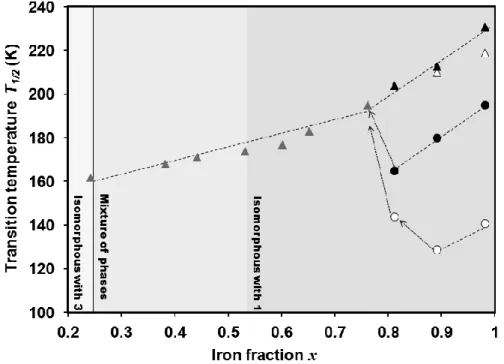
In Chapter 3 the cooperativity in [Fe(bapbpy)(NCS)2] is described, which was studied
by diluting the complex with increasing amounts of its Zn(II) analogue. Although [Fe(bapbpy)(NCS)2] and [Zn(bapbpy)(NCS)2] do not have the same crystal structure,
Zn-diluted samples [FexZn1–x(bapbpy)(NCS)2] adopt the phase of the iron compound
for x > 0.53. In this crystallographic phase the SCO remains two-step down to x = 0.76, to become one-step and lose its hysteresis cycle at lower iron content. The iron-containing molecules keep their SCO properties even at high dilution (x = 0.24), i.e., in the phase of the zinc compound.
In Chapter 4 the synthesis and magnetic properties of the new SCO compounds [Fe(R2bapbpy)(NCSe)2] are presented, i.e., with the same bapbpy derivatives as in
Chapter 2, but with different axial ligands. A trend in the transition temperature of the SCO upon substitution of NCS− by NCSe− is described. The importance of
hydrogen-bonding networks for the cooperativity of [Fe(R2bapbpy)(NCSe)2] SCO compounds is
also described, and compared to that of the thiocyanate analogues.
properties of its iron(II) complexes [Fe(bapphen)(NCX)2] (X = S, or Se) are presented,
and the effect of sample preparation on SCO is highlighted.
In Chapter 6 the synthesis of a new rigid ligand bbpya [bbpya = N,N -bis(2,2’-bipyrid-6-yl)amine] is described. Its high-temperature, cooperative SCO complex [Fe(bbpya)(NCS)2] is described and characterized.
In Chapter 7 the syntheses of a new tetradentate bapphen derivative bearing a long alkyl chain (C12) and two N−H bridges, and of its iron(II) complex, are presented. The self assembly of both the ligand and the complex on HOPG surfaces has been investigated by scanning tunnelling microscopy (STM). Two possible models for the self assembly of the ligand and the complex on HOPG are provided.
Parts of this thesis have been published54, 86 or are in preparation for publication
(Chapters 4, 5, 6 and 7).
1.8
References:
1. O. Kahn and C. J. Martinez, Science, 1998, 279, 44-48.
2. Intel, Intel 22 nm 3D Tri-Gate Transistor Technology, available from: http://newsroom.intel.com/docs/DOC-2032, 2013.
3. R. F. Service, Science, 1996, 274, 1834-1836. 4. J. M. Seminario, Nat. Mater., 2005, 4, 111-113.
5. O. Kahn, J. Kröber and C. Jay, Adv, Mater., 1992, 4, 718-728. 6. L. Cambi and L. Szegö, Ber. Dtsch. Chem. Ges., 1931, 64, 2591-2598. 7. P. Gütlich and H. A. Goodwin, Top. Curr. Chem., 2004, 233, 1-47.
8. P. Gütlich, Y. Garcia and H. A. Goodwin, Chem. Soc. Rev., 2000, 29, 419-427. 9. S. Decurtins, P. Gütlich, K. M. Hasselbach, A. Hauser and H. Spiering, Inorg. Chem.,
1985, 24, 2174-2178.
10. A. Hauser, Coord. Chem. Rev., 1991, 111, 275-290. 11. A. Hauser, Chem. Phys. Lett., 1986, 124, 543-548.
12. C. Roux, D. M. Adams, J. P. Itie, A. Polian, D. N. Hendrickson and M. Verdaguer,
Inorg. Chem., 1996, 35, 2846-2852.
13. J. K. McCusker, M. Zvagulis, H. G. Drickamer and D. N. Hendrickson, Inorg. Chem., 1989, 28, 1380-1384.
14. Y. Garcia, V. Ksenofontov, G. Levchenko, G. Schmitt and P. Gutlich, J. Phys. Chem. B, 2000, 104, 5045-5048.
15. A. Bousseksou, N. Negre, M. Goiran, L. Salmon, J. P. Tuchagues, M. L. Boillot, K. Boukheddaden and F. Varret, Eur. Phys. J. B, 2000, 13, 451-456.
16. V. Meded, A. Bagrets, K. Fink, R. Chandrasekar, M. Ruben, F. Evers, A. Bernand-Mantel, J. S. Seldenthuis, A. Beukman and H. S. J. van der Zant, Phys. Rev. B, 2011, 83, 245415.
17. J. Zarembowitch, New J. Chem., 1992, 16, 255-267.
20. P. J. van Koningsbruggen, Y. Maeda and H. Oshio, Top. Curr. Chem., 2004, 233, 259-324.
21. S. Hayami, Z. Z. Gu, H. Yoshiki, A. Fujishima and O. Sato, J. Am. Chem. Soc., 2001, 123, 11644-11650.
22. H. Werner, B. Ulrich, U. Schubert, P. Hofmann and B. Zimmergasser, J. Organomet. Chem., 1985, 297, 27-42.
23. Y. Garcia and P. Gutlich, Top. Curr. Chem., 2004, 234, 49-62. 24. W. A. Baker and H. M. Bobonich, Inorg. Chem., 1964, 3, 1184-1188. 25. E. Konig and K. Madeja, Chem. Commun., 1966, 61-62.
26. E. Konig and K. Madeja, Inorg. Chem., 1967, 6, 48-55.
27. D. F. Shriver and P. W. Atkins, Inorganic Chemistry, Oxford University Press, Oxford, 3rd edn., 1999.
28. C. K. Jorgensen, Absorption spectra and chemical bonding in complexes, Pergamon Press, Oxford, 1962.
29. A. Hauser, Top. Curr. Chem., 2004, 233, 49-58.
30. O. Kahn, Curr. Opin. Solid State Mat. Sci., 1996, 1, 547-554.
31. P. Gütlich, A. Hauser and H. Spiering, Angew. Chem. Int. Ed., 1994, 33, 2024-2054. 32. E. Konig, K. Madeja and K. J. Watson, J. Am. Chem. Soc., 1968, 90, 1146-1153. 33. B. Gallois, J. A. Real, C. Hauw and J. Zarembowitch, Inorg. Chem., 1990, 29,
1152-1158.
34. G. S. Matouzenko, A. Bousseksou, S. Lecocq, P. J. van Koningsbruggen, M. Perrin, O. Kahn and A. Collet, Inorg. Chem., 1997, 36, 5869-5879.
35. N. Moliner, M. C. Munoz, S. Letard, J. F. Letard, X. Solans, R. Burriel, M. Castro, O. Kahn and J. A. Real, Inorg. Chim. Acta, 1999, 291, 279-288.
36. A. B. Gaspar, M. C. Munoz, N. Moliner, V. Ksenofontov, G. Levchenko, P. Gütlich and J. A. Real, Monatsh. Chem., 2003, 134, 285-294.
37. A. Ozarowski, B. R. McGarvey, A. B. Sarkar and J. E. Drake, Inorg. Chem., 1988, 27, 628-635.
38. S. Bonnet, G. Molnar, J. Sanchez Costa, M. A. Siegler, A. L. Spek, A. Bousseksou, W.-T. Fu, P. Gamez and J. Reedijk, Chem. Mater., 2009, 21, 1123-1136.
39. M. Sorai, J. Ensling, K. M. Hasselbach and P. Gütlich, Chem. Phys., 1977, 20, 197-208.
40. G. Ritter, E. Konig, W. Irler and H. A. Goodwin, Inorg. Chem., 1978, 17, 224-228. 41. M. Hostettler, K. W. Tornroos, D. Chernyshov, B. Vangdal and H. B. Burgi, Angew.
Chem., Int. Ed., 2004, 43, 4589-4594.
42. J. A. Real, M. C. Munoz, E. Andres, T. Granier and B. Gallois, Inorg. Chem., 1994, 33, 3587-3594.
43. S. Bonnet, M. A. Siegler, J. Sanchez Costa, G. Molnar, A. Bousseksou, A. L. Spek, P. Gamez and J. Reedijk, Chem. Commun., 2008, 5619-5621.
44. H. Spiering, T. Kohlhaas, H. Romstedt, A. Hauser, C. Bruns-Yilmaz, J. Kusz and P. Gütlich, Coord. Chem. Rev., 1999, 192, 629-647.
45. J. A. Real, A. B. Gaspar and M. C. Munoz, Dalton Trans., 2005, 2062-2079.
46. J. Jung, G. Schmitt, L. Wiehl, A. Hauser, K. Knorr, H. Spiering and P. Gutlich, Z. Phys. B, 1996, 100, 523-534.
47. J. M. Honig, J. Chem. Educ., 1999, 76, 848-853.
48. C. P. Slichter and H. G. Drickamer, J. Chem. Phys., 1972, 56, 2142. 49. M. Sorai and S. Seki, J. Phys. Chem. Solids, 1974, 35, 555-570. 50. M. Sorai, Top. Curr. Chem., 2004, 235, 153-170.
53. O. Roubeau, M. deVos, A. F. Stassen, R. Burriel, J. G. Haasnoot and J. Reedijk, J. Phys. Chem. Solids, 2003, 64, 1003-1013.
54. Z. Arcis-Castíllo, S. Zheng, M. A. Siegler, O. Roubeau, S. Bedoui and S. Bonnet,
Chem. Eur. J., 2011, 17, 14826-14836.
55. A. Hauser, J. Chem. Phys., 1991, 94, 2741-2748.
56. M. Ohba, K. Yoneda, G. Agusti, M. C. Munoz, A. B. Gaspar, J. A. Real, M. Yamasaki, H. Ando, Y. Nakao, S. Sakaki and S. Kitagawa, Angew. Chem. Int. Ed., 2009, 48, 4767-4771.
57. P. D. Southon, L. Liu, E. A. Fellows, D. J. Price, G. J. Halder, K. W. Chapman, B. Moubaraki, K. S. Murray, J. F. Letard and C. J. Kepert, J. Am. Chem. Soc., 2009, 131, 10998-11009.
58. L. Salmon, G. Molnar, D. Zitouni, C. Quintero, C. Bergaud, J. C. Micheau and A. Bousseksou, J. Mater. Chem., 2010, 20, 5499-5503.
59. J. Kröber, E. Codjovi, O. Kahn, F. Groliere and C. Jay, J. Am. Chem. Soc., 1993, 115, 9810-9811.
60. S. Bonhommeau, G. Molnar, A. Galet, A. Zwick, J. A. Real, J. J. McGarvey and A. Bousseksou, Angew. Chem. Int. Ed., 2005, 44, 4069-4073.
61. A. Bousseksou, G. Molnar, L. Salmon and W. Nicolazzi, Chem. Soc. Rev., 2011, 40, 3313-3335.
62. J. F. Létard, P. Guionneau and L. Goux-Capes, Top. Curr. Chem., 2004, 235, 221-249. 63. J. F. Létard, L. Capes, G. Chastanet, N. Moliner, S. Létard, J. A. Real and O. Kahn,
Chem. Phys. Lett., 1999, 313, 115-120.
64. J. F. Letard, J. Mater. Chem., 2006, 16, 2550-2559.
65. S. Cobo, D. Ostrovskii, S. Bonhommeau, L. Vendier, G. Molnar, L. Salmon, K. Tanaka and A. Bousseksou, J. Am. Chem. Soc., 2008, 130, 9019-9024.
66. M. A. Halcrow, Spin-Crossover Materials: Properties and Applications, John Wiley & Sons, Chichester, 2013.
67. F. Volatron, L. Catala, E. Riviere, A. Gloter, O. Stephan and T. Mallah, Inorg. Chem., 2008, 47, 6584-6586.
68. J. Larionova, L. Salmon, Y. Guarl, A. Tokarev, K. Molvinger, G. Molnar and A. Bousseksou, Angew. Chem. Int. Ed., 2008, 47, 8236-8240.
69. I. Boldog, A. B. Gaspar, V. Martinez, P. Pardo-Ibanez, V. Ksenofontov, A. Bhattacharjee, P. Gutlich and J. A. Real, Angew. Chem., Int. Ed., 2008, 47, 6433-6437. 70. T. Forestier, S. Mornet, N. Daro, T. Nishihara, S. Mouri, K. Tanaka, O. Fouche, E.
Freysz and J. F. Letard, Chem. Commun., 2008, 4327-4329.
71. E. Coronado, J. R. Galan-Mascaros, M. Monrabal-Capilla, J. Garcia-Martinez and P. Pardo-Ibanez, Adv, Mater., 2007, 19, 1359-1361.
72. T. G. Gopakumar, F. Matino, H. Naggert, A. Bannwarth, F. Tuczek and R. Berndt,
Angew. Chem. Int. Ed., 2012, 51, 6262-6266.
73. T. Miyamachi, M. Gruber, V. Davesne, M. Bowen, S. Boukari, L. Joly, F. Scheurer, G. Rogez, T. K. Yamada, P. Ohresser, E. Beaurepaire and W. Wulfhekel, Nat. Commun., 2012, 3, 938-943.
74. P. Gamez, J. S. Costa, M. Quesada and G. Aromi, Dalton Trans., 2009, 7845-7853. 75. D. Gatteschi, A. Cornia, M. Mannini and R. Sessoli, Inorg. Chem., 2009, 48,
3408-3419.
76. A. Grohmann, M. Haryono, K. Student, P. Muller and M. Stocker, Eur. J. Inorg. Chem., 2013, 662-669.
78. S. Shi, G. Schmerber, J. Arabski, J. B. Beaufrand, D. J. Kim, S. Boukari, M. Bowen, N. T. Kemp, N. Viart, G. Rogez, E. Beaurepaire, H. Aubriet, J. Petersen, C. Becker and D. Ruch, Appl. Phys. Lett., 2009, 95.
79. M. Bernien, D. Wiedemann, C. F. Hermanns, A. Kruger, D. Rolf, W. Kroener, P. Muller, A. Grohmann and W. Kuch, J. Phys. Chem. Lett., 2012, 3, 3431-3434.
80. A. Pronschinske, R. C. Bruce, G. Lewis, Y. F. Chen, A. Calzolari, M. Buongiorno-Nardelli, D. A. Shultz, W. You and D. B. Dougherty, Chem. Commun., 2013, 49, 10446-10452.
81. A. Pronschinske, Y. F. Chen, G. F. Lewis, D. A. Shultz, A. Calzolari, M. B. Nardelli and D. B. Dougherty, Nano Lett., 2013, 13, 1429-1434.
82. B. Warner, J. C. Oberg, T. G. Gill, F. El Hallak, C. F. Hirjibehedin, M. Serri, S. Heutz, M.-A. Arrio, P. Sainctavit, M. Mannini, G. Poneti, R. Sessoli and P. Rosa, J. Phys. Chem. Lett., 2013, 4, 1546-1552.
83. M. S. Alam, M. Stocker, K. Gieb, P. Muller, M. Haryono, K. Student and A. Grohmann, Angew. Chem. Int. Ed., 2010, 49, 1159-1163.
84. H. Jacob, K. Kathirvel, F. Petersen, T. Strunskus, A. Bannwarth, S. Meyer and F. Tuczek, Langmuir, 2013, 29, 8534-8543.
85. A. M. Ako, M. S. Alam, M. Rahman, J. P. Hill, N. M. Sanchez-Ballester, K. Ariga, G. Buth, C. E. Anson and A. K. Powell, Chem. Eur. J., 2012, 18, 16419-16425.
2
Increasing the transition temperature of
bapbpy-based mononuclear spin-crossover
compounds: interplay between molecular and
crystal engineering
Abstract
In this chapter, it is shown that different isomers of the same mononuclear iron(II) complex give materials with different spin crossover properties, and that minor modifications of the bapbpy ligand allows for obtaining spin crossover (SCO) near room temperature. A qualitative model is provided to understand the link between the structure of bapbpy-based ligands and the SCO properties of their iron(II) compounds. Thus, seven new trans -[Fe(R2bapbpy)(NCS)2] compounds are reported, where the R2bapbpy ligand bears picoline
(9-12), quin-2-oline (13), isoquin-3-oline (14) or isoquin-1-oline (15) substituents. From this series, three compounds (12, 14 and 15) have SCO properties; for 15 the SCO occurs at 288 K. The crystal structures of compounds 11, 12 and 15 show similar intermolecular interactions to those found in the parent compound [Fe(bapbpy)(NCS)2] (1), in which each
iron complex interacts with its neighbours via NH∙∙∙S hydrogen bonding and π−π stacking. For compounds 12 and 15 hindering groups located near the NH bridges weaken the N∙∙∙S intermolecular interactions, resulting in non-cooperative SCO. For compound 14, the substitution is further away from the NH bridges and the SCO remains cooperative as in 1
14 and 15 and fitted to the Sorai domain model. The number n of like-spin SCO centres per interacting domain, which is related to the cooperativity of the spin transition, was found to be high for compounds 1 and 14 and low for compounds 12 and 15. Finally, it is found that although the compounds 11-12 and 14-15 are pairs of isomers their SCO properties are surprisingly different.
2.1.
Introduction
Iron-based spin crossover (hereafter, SCO) compounds are recognized as highly promising switchable molecular materials,1-4 with potential applications in information
storage,5, 6 image display,7 gas8, 9 or temperature sensors.10 The structure-function
relationship for iron(II)-based SCO compounds has been under discussion for several decades, as it would be remarkable to design de novo an SCO material with pre-defined magnetic properties. In particular, many applications would ideally require materials for which SCO transitions occur near room temperature.11 The occurrence of
cooperative SCO with hysteresis loops is also thought to be critical for information storage applications, as it allows both low spin and high spin (hereafter, LS and HS) states to be populated at one defined temperature.12, 13 The occurrence of the spin
transition is an inherent property of the ligand field strength created by the ligand set around the metal centre;14 thus, transition temperatures should ideally be tunable by
molecular-engineering approaches. Cooperativity is the result of a combination of short- and long-range interactions between individual molecules in the solid state. There are several quantitative models for cooperativity based on the mean-field approach,15 elastic16-19 or electrostatic20 interactions. However, such models only allow
for rationalization of the magnetic behaviour of SCO compounds after the compounds have been synthesized and their properties measured.12 Thus, a qualitative approach
based on molecular engineering is still required in the search of new SCO materials. The mononuclear SCO compound [Fe(bapbpy)(NCS)2] (compound 1; bapbpy = N,N'
-di(pyrid-2-yl)-2,2'-bipyridine-6,6'-diamine, see Scheme 2.1)21 was shown to be highly
cooperative. Its two-step spin crossover features a rather unusual ordered intermediate [HS-LS-LS] phase that is stable over a surprisingly large temperature range.12, 22, 23
Unfortunately, both transition temperatures for this material are too low for any practical applications. Thus, we considered modifying the bapbpy ligand to increase the stability of the LS phase. Seven new trans-[Fe(R2bapbpy)(NCS)2] complexes were
Scheme 2.1. Representations of the ligand bapbpy and its disubstituted derivatives 2-8.
2.2.
Results
The ε,ε’ (2), δ,δ’ (3), γ,γ’ (4), and β,β’ (5) isomers of 6,6’-bis[N-(methyl-2-pyridyl)amino]-2,2’-bipyridine (Me2bapbpy) were synthesized by a
palladium-catalyzed Buchwald-Hartwig coupling reaction that involves the corresponding methyl-substituted -aminopyridine and 2,2’-dibromo-6,6’-bipyridine,24 using KOtBu
as a base (Scheme 2.2). Under the same reaction conditions, the use of quinolin-2-amine, isoquinolin-3-amine and isoquinolin-1-amine led to ligands 6, 7 and 8, respectively.
Scheme 2.2. Synthesis route for bapbpy derivatives 2 to 8. 2 mol% Pd(dba)2 and 4 mol% (S)-BINAP
Coordination of ligands 2-8 to iron(II) thiocyanate was achieved in methanol at room temperature overnight, which leads to compounds 9 to 15, respectively (see formulae in Table 2.1). As neither the free ligands nor their iron complexes are soluble in methanol, Fe(NCS)2 was introduced in excess amount, and the complexes were filtered
and washed with methanol after the reaction to remove the excess amount of metal precursor. The materials were analyzed by IR spectroscopy, magnetic susceptibility measurements, mass spectrometry, 1H NMR in DMSO-d6, and for some of them (10,
11, 12, and 15) by X-ray crystallography and elemental analysis. The IR spectra of the seven solids show the characteristic stretching vibrations of the coordinated thiocyanate ligands (see Table 2.1). By electron-spray mass spectrometry, all compounds showed the molecular peak that corresponds to the monocation [Fe(R2bapbpy)(NCS)]+ (calculated at m/z = 482.08 for 9-12, and 554.09 for 13-15, see
Experimental Part).
Table 2.1. Formulae and infrared thiocyanate stretching vibrations for compounds 9-15. Compound Formula NCS− vibration
mode (cm−1)
9 trans-[Fe(2)(NCS)2] 2056
10 trans-[Fe(3)(NCS)2] 2061 (s), 2093 (m)
11 trans-[Fe(4)(NCS)2] 2075
12 trans-[Fe(5)(NCS)2] 2063
13 trans-[Fe(6)(NCS)2] 2036
14 trans-[Fe(7)(NCS)2] 2062
15 trans-[Fe(8)(NCS)2] 2071 (s), 2110 (m)
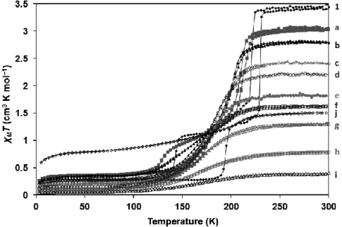
The temperature dependence of the χMT product, in which χM stands for the molar
magnetic susceptibility and T the temperature, was measured for compounds 9-15 in the range 5-300 K, both in the cooling and in the heating modes. The magnetic measurements show that complexes 9, 10, 11 and 13 are in the high-spin (HS) state throughout the whole temperature range, with room-temperature χMT values that range
from 2.7 to 3.4 cm3 K mol−1, and a decrease of χ
MT below 50 K is a typical feature of a
colour at liquid nitrogen temperature, which suggests a reversible spin crossover. As shown in Figure 2.1, the room-temperature χMT value of about 3.5 cm3 K mol−1
remains relatively constant in the temperature range of 275-300 K and indicates an HS Fe(II) species in an octahedral coordination environment.25 In the range 125-275 K the χMT value diminishes gradually to reach 0.05 cm3 K mol−1; it remains close to zero in
the range 5-125 K. The transition temperature for compound 12, determined as the maximum of d(χMT)/dT, was found to be 170(2) K.
For isoquinolin-3-amino compound 14, a similar colour change between room-temperature and liquid-nitrogen room-temperature is observed, however, the evolution of χMT
as a function of T shows different features (Figure 2.1). From 3.51 cm3 K mol−1 at 300
K the value of χMT remains roughly constant until 135 K, at which point it quickly
drops to 0.85 cm3 K mol−1 at 75 K. The transition temperature T
1/2 = 113(2) K was
derived at the maximum of d(χMT)/dT vs. T in the cooling mode. The residual HS
fraction remains roughly constant between 75 and 5 K, at which point the value of χMT
is 0.63 cm3 K mol−1. In the heating mode the transition temperature T
1/2 is higher than
T1/2 [T1/2 = 125(2) K], that is, the SCO behaviour of compound 14 is cooperative and
shows a hysteresis loop characterized by a ΔThyst of approximately 11(3) K.
For isoquinolin-1-amino compound 15, the colour of the crude powder near room temperature is significantly darker than that of compound 11, 12 or 14, but heating the powder under argon allowed for reversibly obtaining the lighter orange colour typical for HS iron(II) compounds based on the bapbpy manifold. Magnetic susceptibility measurements above room temperature confirmed the spin crossover of compound 15, as the value of χMT gradually decreased from 3.34 cm3 K mol−1 at 396 K (the upper
limit of our SQUID magnetometer) down to 0.29 cm3 K mol−1 at 80 K. The spin
crossover was found to occur over a large T range of more than 150 K without any hysteresis loop, which suggests non-cooperative behaviour. The transition temperature for the spin transition, defined as the maximum of d(χMT)/dT vs. T, was estimated to be
Figure 2.1. Plot of χMT vs. T for compounds 11, 12, 14 and 15. There is no apparent hysteresis loop in
the spin crossover for compounds 12 and 15. The dashed line represents magnetic data for powder samples of compound 1.22
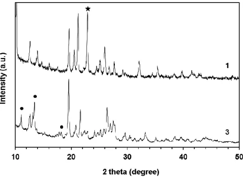
Single crystals suitable for X-ray structure determination were obtained for complexes
10, 11, 12 and 15 by liquid-liquid diffusion method: for compounds 11, 12 and 15, methanol was diffused into a solution of the complex in DMF, whereas for compound
10 the ligand 3 was first dissolved in DMF, followed by layering of 1.1 eq of Fe(NCS)2
Figure 2.2. Displacement ellipsoid plots (50% probability level) at 110(2) K for compounds 10 and
11 in the HS state, and for compounds 12 and 15 in the LS state. Selected labelling is only shown for crystallographically independent atoms. Hydrogen atoms were omitted for clarity.
sphere, thus leaving the two thiocyanate anions in trans positions.
Compound 10 crystallizes in the triclinic space group P-1. The average Fe–N bond length is found at 2.16 Å, which is typical of an HS Fe(II) complex in an FeN6
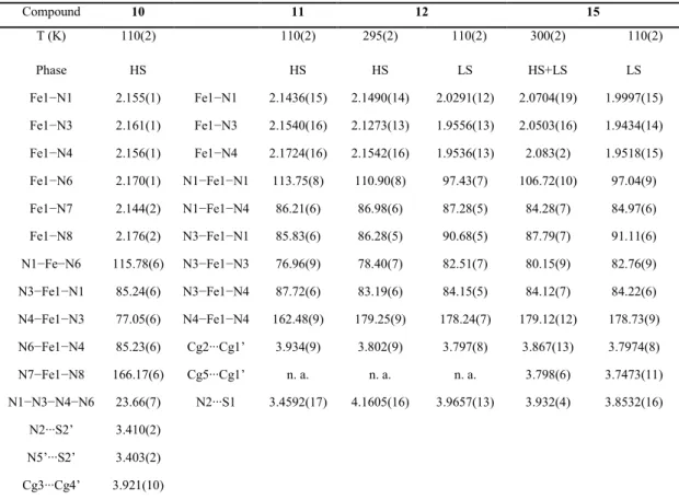
Table 2.2. Selected bond distances (Å) and angles (°) for the HS phase of 10, 11 and for the two phases of 12 and 15.
and 15 the average FeN bond distance at 110 K is around 1.97-1.98 Å, which is characteristic of an LS Fe(II) complex in an FeN6 octahedral environment. For
compound 11 at 110 K and for compound 12 at 295 K, the average FeN bond distance is approximately 2.14-2.16 Å, whereas it is shorter (≈2.07 Å) for complex 15 at 300 K. The latter value is intermediate between those expected for a pure HS and a pure LS Fe(II) centres. This observation is in good agreement with the magnetic susceptibility measurements, which indicate that the SCO is only half-way done at 295 K. Finally, the X-ray diffraction measurements confirm the spin crossovers for compounds 12 and
15. A bond-length analysis for the HS state shows that the Fe1N3 and Fe1N4 bond lengths [2.1350(15) and 2.1481(18) Å, respectively], which involve the bipyridine
Compound 10 11 12 15
T (K) 110(2) 110(2) 295(2) 110(2) 300(2) 110(2)
Phase HS HS HS LS HS+LS LS
Fe1−N1 2.155(1) Fe1−N1 2.1436(15) 2.1490(14) 2.0291(12) 2.0704(19) 1.9997(15) Fe1−N3 2.161(1) Fe1−N3 2.1540(16) 2.1273(13) 1.9556(13) 2.0503(16) 1.9434(14) Fe1−N4 2.156(1) Fe1−N4 2.1724(16) 2.1542(16) 1.9536(13) 2.083(2) 1.9518(15) Fe1−N6 2.170(1) N1−Fe1−N1 113.75(8) 110.90(8) 97.43(7) 106.72(10) 97.04(9) Fe1−N7 2.144(2) N1−Fe1−N4 86.21(6) 86.98(6) 87.28(5) 84.28(7) 84.97(6) Fe1−N8 2.176(2) N3−Fe1−N1 85.83(6) 86.28(5) 90.68(5) 87.79(7) 91.11(6) N1−Fe−N6 115.78(6) N3−Fe1−N3 76.96(9) 78.40(7) 82.51(7) 80.15(9) 82.76(9) N3−Fe1−N1 85.24(6) N3−Fe1−N4 87.72(6) 83.19(6) 84.15(5) 84.12(7) 84.22(6) N4−Fe1−N3 77.05(6) N4−Fe1−N4 162.48(9) 179.25(9) 178.24(7) 179.12(12) 178.73(9) N6−Fe1−N4 85.23(6) Cg2∙∙∙Cg1’ 3.934(9) 3.802(9) 3.797(8) 3.867(13) 3.7974(8) N7−Fe1−N8 166.17(6) Cg5∙∙∙Cg1’ n. a. n. a. n. a. 3.798(6) 3.7473(11) N1−N3−N4−N6 23.66(7) N2∙∙∙S1 3.4592(17) 4.1605(16) 3.9657(13) 3.932(4) 3.8532(16)
N2∙∙∙S2’ 3.410(2) N5’∙∙∙S2’ 3.403(2) Cg3∙∙∙Cg4’ 3.921(10)
chelate and the thiocyanate ions, respectively, are generally longer for compound 11
than for compound 12 (see Table 2.2) or 1.21 In the LS state, longer Fe−N bonds would
account for a weaker ligand field splitting; however in the HS state such conclusion cannot be drawn, because two electrons are located in antibonding orbitals. The absence of spin crossover for compound 11 remains intriguing (see Discussion). The crystal packing of compounds 10, 11, 12 and 15, like for 1,21 are characterized by
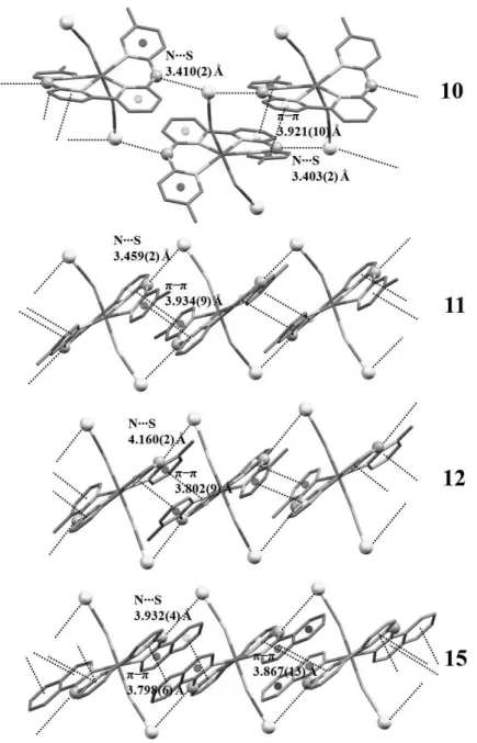
two sets of “supramolecular” interactions found along one-dimensional crystallographic direction (that is, the c axis). The first set includes NH∙∙∙S hydrogen bonds. For compounds 11, 12 and 15, the NH bridges of each tetrapyridyl ligand are donors to the thiocyanate ions of two neighbouring complexes (see Figure 2.3). The N∙∙∙S intermolecular distances are shorter for compound 11 [3.459(2) Å], and are comparable to those found in the HS phase of compound 1 [3.424(2) Å]. By contrast, these distances are significantly longer for the near-room temperature structures of compound 12 [4.160(2) Å] and 15 [3.932(4) Å], indicating weaker NH∙∙∙S intermolecular interactions. Remarkably, compound 10 shows a different N−H∙∙∙S network, where the S atom (Figure 2.3) on one thiocyanate ligand is accepting two N−H∙∙∙S hydrogen bonds of the NH bridges from two neighbouring molecules. The corresponding N∙∙∙S intermolecular distances are the shortest within this family of compounds [3.403(2) Å and 3.410(2) Å at 110 K].
The second set of intermolecular interactions includes π−π stacking between the terminal pyridine rings of two adjacent molecules, as shown in Figure 2.3. The centroid-centroid distances are 3.921(10), 3.934(9) and 3.8018(9) Å for compounds 10,
11 and 12 respectively. Such distances are similar to that found in compound 1
[3.881(1) Å]. For compound 15, each ring of the bipyridine fragment is involved in π−π stacking with the two fused aromatic rings of the isoquinoline groups of the neighbouring molecule, with centroid-centroid distances of 3.798(6) and 3.867(13) Å. Overall, π−π stacking interactions are similar within this family of compounds (that is,
Figure 2.3. Crystal packing along the crystallographic c axis for compounds 10, 11, 12 and 15. Distances are given for the HS (10, 11 and 12) and LS + HS (15) phases.
for both cooling and heating regimes (data not shown), and from 290 to 110 K at 10 K intervals (see Figure 2.4). The first set shows no sign of hysteresis loop in the cell parameters between the cooling and heating regimes. The second set (see Figure 2.4) shows a continuous decrease of V/Z (that is, volume per formula unit) over a large temperature range as T decreases. The drop in V/Z is more pronounced between 140 and 240 K. Overall, temperature dependence of the unit cell dimensions for 12 is consistent with the results of the magnetic susceptibility measurements.
Figure 2.4. Plot of the volume per formula unit V/Z (Å3) versus T (K) for compound 12. Values of
V/Z are measured for the cooling transition HS LS at 10 K intervals.
The SCO transition of Fe(II) compounds in the solid state usually leaves clear signatures in calorimetric measurements, especially in the case of abrupt or cooperative SCO, for which sharp heat capacity peaks are detected. Molar heat capacities were determined at constant pressure, Cp, of compounds 12, 14 and 15 from differential
scanning calorimetry (DSC) experiments. For comparison molar heat capacity for a powder sample of compound 1 is also given, for which DSC traces and excess enthalpy and entropy due to the SCO (SCOH and SCOS) were previously reported.21, 22 The
results are given in Figure 2.5. The excess heat capacity, Cp, due to the spin-crossover
represented as dashed lines in Figure 2.5, and subtracting it from the total heat capacity. In this estimation no heat capacity step at the transition temperature was considered. The deduced calorimetric values associated with the SCO SCOH (integration of Cp
over T) and SCOS (integration of Cp over lnT) are gathered in Table 2.3.
Figure 2.5. Molar heat capacities of compounds 1, 12, 14 and 15 upon warming. Dashed lines are estimated normal heat capacities used for Cp determination. Data for 1 is taken from reference 21.
Figure 2.6. Excess heat capacity associated to the SCO transitions for compounds 1,2112, 14 and 15
![Figure 1.7. (a) Crystal structure of [Fe(H 2 B(pz) 2 ) 2 (phen)] shown along a pseudo-trigonal molecular axis](https://thumb-us.123doks.com/thumbv2/123dok_us/8269960.2190509/22.722.117.613.180.440/figure-crystal-structure-phen-shown-pseudo-trigonal-molecular.webp)
![Figure 3.4. Plots of the HS fraction versus T for different samples [Fe x Zn 1–x (bapbpy)(NCS) 2 ] with different iron fraction x](https://thumb-us.123doks.com/thumbv2/123dok_us/8269960.2190509/65.722.132.598.104.874/figure-plots-fraction-versus-different-samples-different-fraction.webp)
![Figure 3.6. Powder X-ray diffractograms for [Fe x Zn 1–x (bapbpy)(NCS) 2 ] in the range 18-28° (2θ) measured at room temperature](https://thumb-us.123doks.com/thumbv2/123dok_us/8269960.2190509/68.722.116.606.184.558/figure-powder-diffractograms-bapbpy-ncs-range-measured-temperature.webp)
![Figure 3.7. Infrared spectra of [Fe x Zn 1–x (bapbpy)(NCS) 2 ] (samples (a) to (f)), compound 1, and compound 3, in the 2200 to 400 cm −1 region](https://thumb-us.123doks.com/thumbv2/123dok_us/8269960.2190509/70.722.125.613.109.478/figure-infrared-spectra-bapbpy-samples-compound-compound-region.webp)
