Analysis of a packet switch with memories running
slower than the line-rate
*Sundar Iyer, Amr Awadallah, and Nick McKeown
Computer Systems Laboratory, Stanford UniversityStanford, CA 94305-9030 {sundaes, aaa, nickm}@stanford.edu
Abstract -- Our work is motivated by the desire to build a very high speed packet-switch with extremely high line-rates. In this paper, we consider building a packet-switch from multiple, lower speed packet-switches operat-ing independently and in parallel. In particular, we consider a (perhaps obvi-ous) parallel packet switch (PPS) architecture in which arriving traffic is demultiplexed over identical, lower speed packet-switches, switched to the correct output port, then recombined (multiplexed) before departing from the system. Essentially, the packet-switch performs packet-by-packet load-balancing, or “inverse-multiplexing” over multiple independent packet-switches. Each lower-speed packet switch, operates at a fraction of the line-rate, ; for example, if each packet-switch operates at rate no memory buffers are required to operate at the full line-rate of the system. Ideally, a PPS would share the benefits of an output-queued switch; i.e. the delay of individual packets could be precisely controlled, allowing the provision of guaranteed qualities of service. In this paper, we ask the question: Is it possi-ble for a PPS to precisely emulate the behavior of an output-queued packet-switch with the same capacity and with the same number of ports? The main result of this paper is that it is theoretically possible for a PPS to emulate a FCFS output-queued packet-switch if each layer operates at a rate of approximately . This simple result is analogous to Clos’ theorem for a three-stage circuit switch to be strictly non-blocking. We further show that the PPS can emulate any QoS queueing discipline if each layer operates at a rate of approximately .
Keywords--packet-switch; output-queueing; inverse-multiplexing; load-bal-ancing; Clos’ network.
I. INTRODUCTION
Wavelength division multiplexing (WDM) is making available long-haul fiber-optic links with very high capacity. WDM makes this possible by allowing a single fiber to contain multiple sepa-rate channels; today each channel typically opesepa-rates at OC48c (2.5Gb/s), OC192c (10Gb/s) and in some systems at OC768c (40Gb/s). The packets or cells carried on each WDM channel are switched, or routed, by packet-switches (e.g. ATM switches, Frame Relay switches and IP routers) that process and then switch packets between different channels. It would be desirable to process packets in the optical domain, without conversion to electronic form. However, all packet-switches need buffering (by definition), and it is not economically feasible today to store packets optically. And so packet-switches will continue to use electronic buffer memories for some time to come.
But at the data rates anticipated for individual WDM channels, we may not be able to buffer packets at the speed at which they arrive and depart. For example, if a memory is 512-bits wide,1 and buffers packets for a 160Gb/s WDM channel, the memory
k
R R k⁄
2R k⁄
3R k⁄
needs to perform a read or write operation every 1.6ns. This is impractical today; and unfortunately the time to perform a ran-dom access into an affordable memory is decreasing only slowly with time.
It is the overall goal of our work to design a high capacity packet-switch (e.g. multiple terabits/second) that: (1) Supports individual line-rates in excess of the speeds of available elec-tronic memory, and (2) Is capable of supporting the same quali-ties of service as an output-queued switch. These two goals cannot be realized alone by a conventional output-queued (OQ) switch; this is because OQ switches require buffer memory that operates at times the line-rate, where is the number of ports of the switch. This certainly doesn’t meet our goal of memory running slower than any individual line-rate.
Likewise, we can’t use the other widely used techniques for reducing memory bandwidth; namely, input-queued (IQ) and combined input and output queued (CIOQ) switches. In an input-queued switch each memory operates at the same speed as the external line-rate. While an improvement over OQ switches nei-ther of our goals are met: (1) An IQ switch does not meet our requirement to use memories slower than the external line-rate, and (2) IQ switches are unable to provide the same QoS guaran-tees as an OQ switch. Because of the limited QoS capabilities of IQ switches, CIOQ switches were studied and recently, it was shown that a variety of qualities of service are possible in a CIOQ switch in which the memory operates at twice the line-rate [1]. Obviously, this doesn’t meet our goal for memory speed.
We would like an architecture that overcomes these limitations, yet is practical. To this end, we consider here a parallel packet-switch (PPS) architecture comprised of multiple identical lower-speed packet-switches operating independently and in parallel. An incoming stream of packets is spread, packet-by-packet, by a demultiplexor across the slower packet-switches, then recom-bined by a multiplexor at the output. As seen by an arriving packet, a PPS is a single-stage packet-switch; all of the buffering is contained in the slower packet-switches, and hence our first goal is met because no buffers in a PPS need run as fast as the external line-rate. The demultiplexor selects an internal packet-switch (or “layer”) and sends the arriving packet to that layer, where it is queued awaiting its departure time. When the packet’s departure time arrives, the multiplexor requests that the packet be removed from its queue, and places the packet on the outgoing
1.512-bits, or 64-bytes is about the maximum that is practical or
effi-cient because of ATM cell size and average packet sizes.
N N
*This research was supported by the National Science Foundation, under NGI
contract ANI-9872761, the Industrial Technology Research Institute (Taiwan) and the Alfred P. Sloan Foundation.
line.
It is an important characteristic of a PPS that the multi-plexor and demultimulti-plexor functions contain no buffering. However, they must make intelligent decisions; and as we shall see, the precise nature of the demultiplexing (“spread-ing”) and multiplexing functions are key to the operation of the PPS.
We are interested in the question: Can we select the demultiplexing and multiplexing functions so that a PPS can precisely emulate, or mimic, the behavior of an output-queued switch? Two different switches are said to mimic each other, if under identical inputs, identical packets depart from each switch at the same time [2]. If it is possible for a PPS to mimic an output-queued switch, it will be possible to control delay of individual packets and therefore provide QoS. In this paper we show that a PPS can precisely emulate an output-queued switch which provides delay guarantees. Furthermore, each layer of the PPS may consist of a single CIOQ switch with memories operating slower than the rate of the external line.
We are not aware of any literature on the PPS architecture, but the architecture itself is not novel; “load-balancing” and “inverse-multiplexing” systems [3][4] have been around for some time, and this architecture is a simple extension of these ideas. There is similar work, which studied inverse ATM multiplexing and how to use sequence numbers to re-synchronize cells sent through parallel switches or links [5][6][7][8]. However, we are not aware of any analytical studies of the PPS architecture. As we shall see, there is an interesting analogy between the (buffered) PPS architecture and the (unbuffered) Clos Network [9].
II. DEFINITIONS
Before proceeding, it will be useful to define some terms used throughout this paper:
Cell: A fixed-length packet; not necessarily equal in length to a 53-byte ATM cell. For the purposes of this paper, although packets arriving to the switch may have variable length, we will assume that they are processed and buffered internally as fixed length “cells”. This is common practice in high performance routers; variable length packets are seg-mented into cells as they arrive, carried across the switch as cells, and reassembled back into packets before they depart. Time slot: Refers to the time taken to transmit or receive a fixed length cell at a link rate of .
Output-Queued (OQ) Switch: A switch in which arriv-ing packets are placed immediately in queues at the output, where they contend with packets destined to the same output waiting their turn to depart. The departure order may simply be first-come first-served (FCFS) in which case we call it a FCFS-OQ switch. Other service disciplines, such as WFQ [10], GPS [11], Virtual Clock [12], and DRR [13] are widely
R
used to provide QoS guarantees. A characteristic of an OQ switch is that the buffer memory must be able to accept (write) new cells per time-slot where is the number of ports, and read one cell per cell time. Hence, the memory must operate at times the line-rate.
Input-Queued (IQ) Switch: A switch in which arriving cells are queued at the input, where they contend with pack-ets waiting to go to any output. The service discipline is determined by a switch scheduler, or arbiter, which removes at most one cell per time-slot from each input, delivers it across a (usually non-blocking) switch-fabric and onto the outgoing line. A characteristic of an IQ switch is that the buffer memory need only write and read one new cell per time-slot. Hence, the memory must operate at twice the line-rate.
Work-conserving: A system is said to be work-conserving if its outputs never idle unnecessarily. In the context of a packet-switch, this means that an output never idles when there is a cell in the buffers of the packet-switch destined to that output. A consequence of a system being work-conserv-ing is that the throughput is maximized, and the average latency of cells is minimized. An input-queued switch is not, in general, work-conserving because a cell can be held at an input queue while its output idles. An output-queued switch is work-conserving, and so a necessary, but not sufficient, condition for a switch to mimic output-queueing is that it be work-conserving.
PIFO Queues: A “Push-In First-Out” queue ordering is defined according to the following rules:
1. Arriving cells are placed at (or, “push-in” to) an arbitrary location in the queue,
2. The relative ordering of cells in the queue does not change once cells are in the queue, i.e. cells in the queue cannot switch places, and
3. Cells may be selected to depart from the queue only from the head of line.
PIFO queues are quite general and can be used to imple-ment QoS scheduling disciplines such as WFQ, GPS and strict priorities.
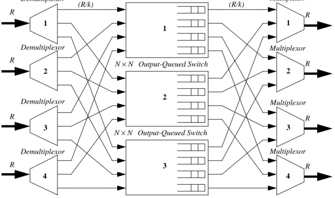
III. THEPARALLELPACKETSWITCHARCHITECTURE In this paper we focus on the specific type of PPS illus-trated in Figure 1 in which the center-stage switches are OQ. The figure shows a PPS, with each port operating at rate . Each port is connected to all three output-queued switches (we will refer to the center-stage switches as “lay-ers”). When a cell arrives at an input port, the demultiplexor selects a layer to send the cell to; the demultiplexor makes its
N N
N+1
4×4
choice of layer using a policy that we will describe later. Since the cells from each external input, of line rate , are spread (“demultiplexed”) over links, each input link must run at a speed of at least , otherwise buffering (operat-ing at the line-rate) would be required in the demultiplexor. Each of the layers receive cells from the input ports, then switches each cell to its output port. During times of conges-tion, cells are stored in the output-queues of the center-stage, waiting for the line to the multiplexor to become available. When the line is available, the multiplexor selects a cell from among the corresponding output queues in each layer. Since each multiplexor receives cells from output queues, the queues must operate at a speed of at least to keep the external line busy.
Externally the switch appears as an switch with each port operating at rate . Note that neither the muli-plexor nor the demultimuli-plexor contain any memory, and that they are the only components running at rate .
We can compare the memory-bandwidth requirements of an parallel packet-switch with those for an OQ switch with the same aggregate bandwidth. In an OQ switch, the memory bandwidth must be at least , and in a PPS
at least . But we can reduce the memory band-width further using a CIOQ switch. From [1], we know that an OQ switch can be mimicked precisely by a CIOQ switch operating at a speedup of two. So, we can replace each of the output-queued switches in the PPS with a CIOQ switch, without any change in operation. The memory bandwidth in the PPS is reduced to , (one read operation and two write operations per cell time) which is independent of ,
R k R k⁄ N k k R k⁄ N×N R R N×N N+1 ( )R N+1 ( )R k⁄ 3R k⁄ N
and may be reduced arbitrarily by increasing , the number of layers.
A. The need for speedup
It is tempting to assume that, because each layer is output queued, it is possible for the PPS described above to perform identically to an OQ switch. This is actually not the case unless we use speedup. To see why, we demonstrate that without speedup a PPS is not work-conserving, and hence cannot mimic an OQ switch.
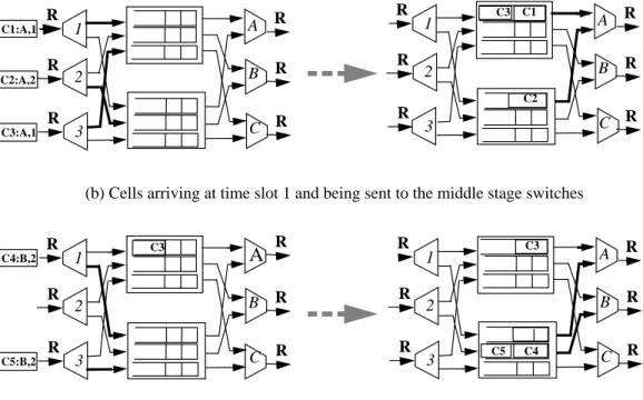
Consider the PPS in Figure 2 with three ports and two lay-ers ( and ). The external lines operate at rate
, and the internal lines at rate .
Assume that the switch is empty at time , and that three cells arrive, one to each input port, and all destined to output port . At least two of these inputs will choose the same layer. Let inputs 1 and 3 both choose layer 1 and send cells and to layer 1 in the first time slot. This is shown in Figure 2a. Input port 2 sends cell to layer 2. These cells are shown in the output queues of the internal switches and await departure. In the second time slot, both the input ports which sent cells to the same layer in the first time slot, receive cells destined to output port . As shown in the figure, cells and arrive at input ports 1 and 3 and they both must be sent to layer 2; this is because the internal line rate between the demultiplexor and each layer is only , limiting a cell to be sent over this link only once every other time-slot. Now the problem becomes apparent: cells and are in the same layer, and they are the only
k N = 3 k = 2 R R 2⁄ t = 0 A C1 C3 C2 B C4 C5 R 2⁄ C4 C5 R R R R R (R/k) (R/k) Multiplexor Demultiplexor 1 R Demultiplexor 2 R Demultiplexor 3 Demultiplexor R 1 2 3 Multiplexor Multiplexor Multiplexor Output-Queued Switch N×N Output-Queued Switch N×N Output-Queued Switch N×N
Figure 1: The architecture of a Parallel Packet Switch based on output-queued switches.
4 4
1
2
cells in the system destined for output port at time slot . These two cells cannot be sent back-to-back in consecutive time-slots, because the link between the layer and the multi-plexor operates only at rate . So, cell will be sent, followed by an idle time-slot at output port , and the sys-tem is no longer work-conserving. Hence, the syssys-tem cannot mimic an OQ switch.
Definition 1: Concentration: Concentration is a term we will use to describe the situation when a disproportionately large number of cells destined to the same output are con-centrated on a small number of the internal layers.
Concentration is undesirable as it leads to unnecessary idling because of the limited line-rate between each layer and the multiplexor. One way to alleviate the effect of con-centration is to use faster internal links. In general, we will use internal links that operate at a rate , where is the speedup of the internal link.
For example, in our counter-example above, the problem could be eliminated by running the internal links at a rate of instead of (i.e. a speedup of two). This solves the problem because the external output port can now read the cells back-to-back from layer two. But this appears to defeat the purpose of operating the internal layers slower than the external line rate. Fortunately, we will see in the next section that the speedup required to eliminate the problem of con-centration is independent of the arriving traffic, , and is almost independent of . In particular, we find that with a
speedup of , for large k, the PPS is
work-conserving and can precisely mimic a FCFS-OQ switch.
B 1 R 2⁄ C4 B S R k( ⁄ ) S R R 2⁄ R N k 2k⁄ (k+2) ≈2 B. Link Constraints
The operation of a PPS is limited by two constraints. We call these the Input Link Constraint and the Output Link Constraint as defined below.
Definition 2: Input Link Constraint- An external input port is constrained to send a cell to a specific layer at most once every time slots. This is because the internal input links operate times slower than the external input links. We call this constraint the input link constraint, or ILC. Definition 3: Allowable Input Link Set- The ILC gives rise to the allowable input link set, AIL(i,n), which is the set of layers to which external input port can start sending a cell in time slot n. This is the set of layers that external input has not started sending any cells within the last
time slots. Note that .
evolves over time, with at most one new layer being added to, and at most one layer being deleted from the set in each time slot. If external input starts sending a cell to layer at time slot , then layer is removed from . The layer is added back to the set when it
becomes free at time .
Definition 4: Output Link Constraint- In a similar manner to the ILC, a layer is constrained to send a cell to an external output port at most once every time slots. This is because the internal output links operate times slower than the external output links. Hence, in every time slot an
k S⁄ S k⁄ i i k S⁄ –1 AIL i n(, ) ≤k,∀(i n, ) AIL i n(, ) i l n l AIL i n(, ) n+ k S⁄ k S⁄ S k⁄
Figure 2: A PPS with an arrival pattern that makes it non work-conserving. The notation denotes a cell numbered , destined to output port , and sent to layer .
3x3 Ci:A, m i A m R R2 3 1 R R R R R B C A C1:A,1 C2:A,2 C3:A,1 R R2 3 1 R R R R R B C A C1 C2 R R2 3 1 R R R R B C C4:B,2 C5:B,2 R2 3 1 R R R R R B C A C3 C4 R C5 C3 C3
(a) Cells arriving at time slot 0 and being sent to the middle stage switches
(b) Cells arriving at time slot 1 and being sent to the middle stage switches
R
A
external output port may not be able to receive cells from certain layers. This constraint is called the output link con-straint, or OLC.
Definition 5: Departure Time- When a cell arrives, the demultiplexor selects a departure time for the cell. A cell arriving to input at time slot and destined to output is assigned the departure time . The departure time could, for example, be the first time that output is free and able to send the cell. As we shall see later, other definitions are possible.
Definition 6: Available Output Link Set- The OLC gives rise to the available output link set , which is
the set of layers that can send a cell to external output at time slot in the future. is the set of layers that have not started sending any cells to exter-nal output in the last time slots before time slot . Note that, since there are a total of layers,
.
Like , can increase or
decrease by at most one layer per time slot; i.e. if a layer starts to send a cell to output at time slot , the
layer is deleted from and then will be
added to the set again when the layer becomes free at time . However, whenever a layer is deleted from the set, the index is incremented. Because in a single time slot up to cells may arrive at the PPS for
the same external output, may change up
to times per time slot. This is because
represents the layers available for use at some time in the future. As each arriving cell is sent to a layer, a link to its external output is reserved for some time in
the future. So effectively, indicates the
schedule of future departures for output , and at any instant, indicates the first time in the future that output will be free.
C. Lower Bounds on the size of the link constraint sets
The following two lemmas will be used shortly to demon-strate the conditions under which a PPS can mimic a FCFS-OQ switch.
Lemma 1: The size of the available input link set, , for all ; where is the speedup on the internal input links.
Consider external input port . The only layers that can-not send a cell to are those which were used in the last
time slots. (The layer which was used
time slots ago is now free to be used again). is minimized when a cell arrives to the external input port in
each of the previous time slots, hence
.❒ i n j DT n i j( , , ) j AOL j DT n i j(, ( , , )) j DT n i j( , , ) AOL j DT n i j(, ( , , )) j k S⁄ –1 DT n i j( , , ) k AOL j DT n i j(, ( , , )) ≤k,∀(j DT n i j, ( , , )) AIL i n(, ) AOL j DT n i j(, ( , , )) l j DT n i j( , , ) AOL j DT n i j(, ( , , )) DT n i j( , , )+ k S⁄ DT n i j( , , ) N AOL j DT n i j(, ( , , )) N AOL j DT n i j(, ( , , )) DT n i j( , , ) AOL j DT n i j(, ( , , )) j Max DT n i j( ( , , )) +1,∀(n i, ) j AIL i n(, ) ≥k– k S⁄ +1 i n, ≥0 S i i k S⁄ –1 k S⁄ AIL i n(, ) k S⁄ –1 AIL i n(, ) ≥k– ( k S⁄ –1) = k– k S⁄ +1
Lemma 2: The size of the available output link set, , for all .
Proof: The proof is similar to Lemma 1. We consider an external output port which reads cells from the internal switches instead of an external input port which writes cells to the internal switches.❒
IV. MIMICKING AFCFS-OQSWITCH
Theorem 1: (Sufficiency) If a PPS guarantees that each arriving cell is allocated to a layer , such that
and , (i.e. if it meets both the ILC and the OLC) then the switch is work-conserving.
Proof: Consider a cell that arrives to external input port at time slot and destined for output port . The demulti-plexor chooses a layer that meets both the ILC and the
OLC; i.e. , where
is the index of and represents the first time that external output is free in the future at time slot . Since the ILC is met, is sent to layer immediately with-out buffering. is placed in output queue of layer l where it awaits its turn to depart. In fact, the departure time of the cell has already been picked when it arrived at time . is removed from its queue at and sent to external output port . The reason that departs at
is because, by definition of ,
external port was busy receiving cells from other layers up until the time departs, and hence the output was never idle when there was a cell in the system destined to it.❒
Theorem 2: (Sufficiency) A speedup of is sufficient for a PPS to meet both the input and output link constraints for every cell.
For the ILC and OLC to be met, it suffices to show that
there will always exist a layer such that
, i.e. that , which must be
satis-fied if . From Lemma 1
and Lemma 2 we know that
if .❒
Corollary 1: A PPS can be work conserving, if .
Having shown that a PPS can be work-conserving, we now show that with the same speedup, the switch can mimic a FCFS-OQ switch.
Theorem 3: (Sufficiency) A PPS can exactly mimic a FCFS-OQ switch with a speedup of .
Proof: Consider a PPS with a speedup of
which, for each arriving cell, selects a layer that meets both the ILC and the OLC. A cell destined to output and
arriv-AOL j DT n i j(, ( , , )) ≥k– k S⁄ +1 i j n, , ≥0 l l∈AIL i n(, ) l∈AOL j DT n i j( , ( , , )) C i n j l l∈ {AIL i n(, )∩AOL j DT n i j(, ( , , ))} DT n i j( , , ) AOL .( ) j n C l C j DT n i j( , , ) n C DT n i j( , , ) j C DT n i j( , , ) AOL j DT n i j(, ( , , )) j C 2k⁄(k+2) l l∈ {AIL i n(, )∩AOL j DT n i j(, ( , , ))} AIL i n(, )∩ (AOL j DT n i j(, ( , , ))) ≠∅ AIL i n(, ) + AOL j DT n i j(, ( , , )) >k AIL i n(, ) + AOL j DT n i j(, ( , , )) >k S>2k⁄ (k+2) S>2k⁄ (k+2) S>2k⁄(k+2) S>2k⁄(k+2) j
ing at time slot is scheduled to depart at time slot
, which is the index of . By
definition of , is the first time
in the future that output is idle, and so it is also the time that the cell would depart in a FCFS-OQ switch. Therefore, each cell departs at the same time that it would in a FCFS-OQ switch, and hence the PPS mimics its behavior.❒
A detailed description of the algorithm suggested by this proof appears in Appendix A. It is interesting to note that this theorem is in some ways analogous to the requirements for a 3-stage Clos network to be strictly non-blocking. In fact, the proof is quite similar. Yet the two systems are clearly different — a PPS buffers cells as they traverse the switch, while a Clos network is a bufferless fabric used mostly in circuit-switches.
V. PROVIDINGQOSGUARANTEES
We now extend our results to find the speedup requirement for a PPS to provide the same QoS guarantees as an OQ switch. To do this, we find the speedup required for a PPS to implement any PIFO scheduling discipline.
Theorem 4: (Sufficiency) A PPS can exactly mimic any OQ switch with a PIFO queueing discipline with a speedup
of .
Proof: As defined in Section II a PIFO queueing policy can insert a cell anywhere in its queue but it can not change the relative ordering of cells once they are in the queue. Con-sider a cell that arrives to external input port at time slot and destined for output port . The demultiplexor will determine the time that each arriving cell must depart, to meet its delay guarantee. The decision made by the demultiplexor at input amounts to selecting a layer so that the cell may depart on time. Notice that this is very similar to the previous section in which cells departed in FCFS order requiring only that a cell depart the first time that its output is free after the cell arrives. The difference here is that may be selected to be ahead of cells already scheduled to depart from output . The demulti-plexor’s choice of layer to send an arriving cell must meet three constraints:
1. The link connecting layer to output must be free at
. i.e. .
2. All the other cells destined to output after must also find a link available. In other words, if the demultiplexor picks layer for cell , it needs to ensure that no other cell requires the link from to output within the next time slots. Since the cells following cell C have already been sent to specific layers, it is necessary that the layer being chosen be distinct from the layers
which the next cells use. Formally we can
write this constraint as
n DT n i j( , , ) AOL j DT n i j(, ( , , )) AOL j DT n i j(, ( , , )) DT n i j( , , ) j S>3k⁄ (k+3) C i n j DT n i j( , , ) i DT n i j( , , ) j l C l j DT n i j( , , ) l∈ {AOL j DT n i j(, ( , , ))} j C l C l j k S⁄ –1 ( ) l k S⁄ –1 l∈ {AOL j DT n i j(, ( , , )+ k S⁄ –1)}
3. The link connecting the demultiplexor at input to layer
must be free at time slot . Hence .
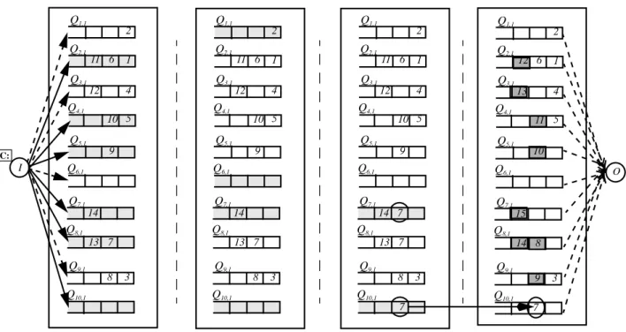
Figure 3 shows an example of a PPS with layers and . A new cell arrives destined to output and has to be inserted in the priority queue for output which is maintained in a PIFO manner. Figure 3a shows that the cell is constrained by the AIL to be sent to layers . These layers are shown darkened in Fig-ure 3a. It is decided that cell must be inserted between and . Figure 3b shows the intersection of the two AOL sets for this insertion. Cell is constrained by the
AOL to use layers . Figure 3c shows the
can-didate layers for insertion i.e. layers and . Cell is then inserted in layer .
VI. CONCLUSIONS
While it is difficult to predict the growth of the Internet over the coming years, it seems certain that packet-switches will be required with: (1) increased switching capacity, (2) support for higher line-rates, and (3) support for differenti-ated qualities of service. All three of these requirements present challenges of their own. For example, higher capac-ity switches may require new architectures; higher line-rates may grow to exceed the capabilities of commercially avail-able memories, making it impractical to buffer packets as they arrive; and the need for differentiated qualities of ser-vice may require performance comparable to output-queued switches. The difficulty of overcoming these challenges could be seen as an argument for circuit switching where switching is simple, buffers are not needed, and qualities of service are achieved through peak-provision of bandwidth.
While the use of circuit-switching may be appealing, we consider here an alternative — a parallel packet switch (PPS) which achieves high capacity by placing multiple packet switches in parallel, rather than in series with each other as is common in multistage switch designs. Hence, each packet that passes through the system encounters only a single stage of buffering; furthermore, and most interestingly, the system
i
l n l∈ {AIL i n(, )}
Thus layer must meet all the above constraints i.e.
For a layer to exist,
This will be satisfied when,
From Lemma [1] and [2] we know that,
if, .❒ l l AIL i n(, ) AOL j DT n i j(, ( , , )) AOL j DT n i j∈ {( , ( , ,∩)+ k S⁄ –1)} ∩ l AIL i n(, ) AOL j DT n i j(, ( , , )) AOL j DT n i j( , ∩( , , )+ k S⁄ –1∩) ≠∅ AIL i n(, ) AOL j DT n i j(, ( , , )) AOL j DT n i j(, ( , , )+ k S⁄ –1) + + 2k > AIL i n(, ) AOL j DT n i j(, ( , , )) AOL j DT n i j(, ( , , )+ k S⁄ –1) + + 2k > S>3k⁄(k+3) k = 10 S = 3 C 1 1 2 4 5 7 8 10, , , , , { } C C6 C7 C 1 6 7 10, , , { } 7 10 C 10
line-rates may operate in excess of the speed of the buffer memory. The main result of this paper is that it theoretically possible to build such a PPS that exactly mimic an output-queued packet switch regardless of the nature of the arriving traffic. The mimicking can be maintained even when the sys-tem is providing guaranteed qualities of service. In short, and at first glance, it appears that all three of the challenges out-lined above are overcome by the PPS system.
Unfortunately, as described above, the result is only a the-oretical one. There are two hindrances to making the PPS practical. First, each layer of the PPS is an output-queued (OQ) switch itself, which implies that the speed of its buffer memory must grow linearly with the number of ports of the PPS. We can overcome this by replacing each output-queued switch with a Combined Input-Output Queued (CIOQ) switch that mimics its behavior using an internal speedup of two. Each memory in the system could now run at a rate independent of the number of ports of the PPS, and can be made arbitrarily small by increasing the number of packet-switches used. This solution, however, requires that the CIOQ switch be made practical — something for which work is in progress, but no solution is yet available.
The second hindrance is that the theoretical result assumes a centralized algorithm to determine which layer each arriv-ing cell is sent to. We believe that the algorithm may take too long to run, as its running time grows linearly with the num-ber of ports of the PPS.
So, in summary, we think of this work as a first step towards building high-capacity switches that support guaran-teed qualities of service in which memory bandwidth is not the bottleneck. In our future work, we will strive to make these results more practical.
ACKNOWLEDGMENTS
We would like to thank Pankaj Gupta of Stanford Univer-sity for his many useful comments along the way.
REFERENCES
[1] S. Chuang, A. Goel, N. McKeown, B. Prabhakar, “Matching output queueing with a combined input/output-queued switch,” IEEE J.Sel. Areas in Communications, Vol. 17, no. 6, pp. 1030-1039, June 1999. [2] B. Prabhakar and N. McKeown, “On the speedup required for
com-bined input and output queued switching,” Automatica, Vol. 35, pp. 1909-1920, December 1999.
[3] P. Fredette, “The past, present, and future of inverse multiplexing,” IEEE Communications, pp. 42-46, April 1994.
[4] J. Duncanson, “Inverse multiplexing”, IEEE Communications, pp. 34-41, April 1994.
[5] J. Turner, “Design of a broadcast packet switching network,” IEEE Trans. on Communications, pp. 734-743, June 1988.
[6] H. Kim, A. Leon-Garcia, “A self-routing multistage switching net-work for broadband ISDN,” IEEE J. Sel. Areas in Communications, pp. 459-466, April 1990.
[7] I. Widjaja, A. Leon-Garcia, “The helical switch: A multipath ATM switch which preserves cell sequence,” IEEE Trans. on Communica-tions, Vol. 42, no. 8, pp. 2618-2629, Aug 1994.
[8] F. Chiussi, D. Khotimsky, S. Krishnan, “Generalized inverse
multi-Q1,1 Q3,1 Q4,1 Q5,1 Q6,1 Q7,1 Q8,1 Q9,1 Q10,1 Q2,1 2 1 4 5 3 6 10 9 7 8 11 12 14 13 Q1,1 Q3,1 Q4,1 Q5,1 Q6,1 Q7,1 Q8,1 Q9,1 Q10,1 Q2,1 2 1 4 5 3 6 10 9 7 8 11 12 14 13 Q1,1 Q3,1 Q4,1 Q5,1 Q6,1 Q7,1 Q8,1 Q9,1 Q10,1 Q2,1 2 1 4 5 3 6 10 9 7 8 11 12 14 13 Q1,1 Q3,1 Q4,1 Q5,1 Q6,1 Q7,1 Q8,1 Q9,1 Q10,1 Q2,1 2 1 4 5 3 6 11 8 9 12 13 15 14 I O 7 7 10
Figure 3: Insertion of cells in a PIFO order in a PPS with ten layers.Qk,1 refers to output queue number one in the internal switch k. (a) The AIL
con-strains the use of layers . (b) The cell is to be inserted before cell number 7. The two AOLs constrain the use of layers (c) The intersection constrains the use of layers {7,10}. (d) Layer 10 is chosen. The cell number 7 is inserted.
2 4 5 7 8 10, , , , ,
{ } {1 6 7 10, , , }
7
C:
(a) AIL and the existing PIFO order
Step 1 Step 2 Step 3 Step 4
(b) Intersection of the two AOL sets
(c) Candidate layers for insertion of cell
(d) New PIFO order after insertion
plexing of switched ATM connections,” in Proc. IEEE Globecom ‘98 Conference. The Bridge to Global Integration, Sydney, Australia, Nov. 1998.
[9] C. Clos, “A study of non-blocking switching networks,” Bell Systems Technical Journal 32, 1953.
[10] A. Demers, S. Keshav; S. Shenker, “Analysis and simulation of a fair queueing algorithm,” J. of Internetworking: Research and Experi-ence, pp.3-26, 1990.
[11] A. Parekh and R. Gallager, “A generalized processor sharing ap-proach to flow control in integrated services networks: the single node case,” IEEE/ACM Transactions on Networking, vol. 1, no. 3, pp. 344-357, June 1993.
[12] L. Zhang, “Virtual Clock: A new traffic control algorithm for packet switching networks,” ACM Transactions on Computer Systems, vol.9 no.2, pp.101-124, 1990.
[13] M. Shreedhar and G. Varghese, “Efficient fair queueing using deficit round robin,” in Proc. ACM Sigcomm, Sep 1995, pp. 231-242.
APPENDIX A: A Centralized Algorithm for a PPS We now present an insert and dispatch scheme, called CPA (Centralized Parallel Packet Switch Algorithm) in order to emulate a FCFS-OQ switch based on the results obtained in Section IV.
A. Notation
1. , denotes the head of line of cell at output port of internal switch .
2. , denotes the sequence number tagged to a cell which is destined to output port The sequence denotes the FIFO order of all cells destined to output port
. These tags are unique for each cell destined to output port .
B. Steps in CPA
CPA consists of two parts which operate independently at each of the external input and the output ports. There is a centralized scheduler which maintains the allowable output link set for each output.
1. De-multiplexor: Each external input port maintains its allowable input link set. When a cell arrives to external input port destined to output port at time slot , the input port requests the centralized scheduler for a layer. A copy of , and as well as the destination port number is sent. The centralized scheduler then
com-putes a layer , such that
, as described in Theorem 1. The centralized scheduler also returns a tagged sequence number associated with the arriving cell . The external input tags the cell with the
HOL j l(, ) j l T c j( , ) c j T c j( , ) j j c i j n AIL i n(, ) j l l∈ {AIL i n(, )∩AOL j DT n i j(, ( , , ))} T c j( , ) c i
output port number and sequence number and transmits the cell to layer . The values of ,
, and are updated. 2. Multiplexor: We assume that the cells at the output
queues of the internal switches are maintained in sorted order in the ascending order of their sequence numbers. Each external output port computes a layer such that . The output port chooses this layer to dispatch the next cell.
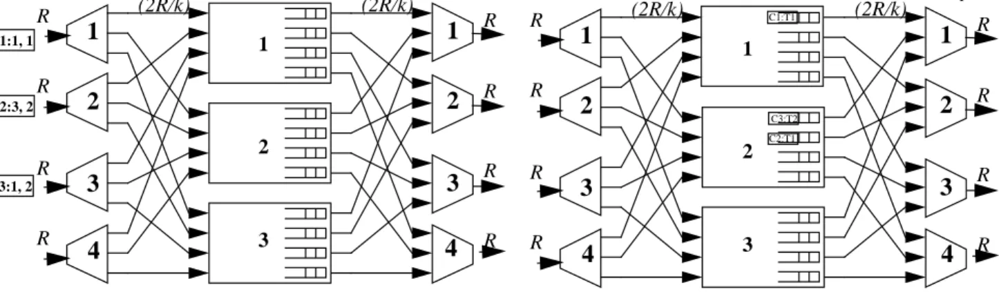
In the example shown in Figure 4a at the input cells ,
, arrive at a PPS with layers and
at time . These cells are sent to layers respectively. The AIL and the AOL is updated at the input after each cell is sent. Cells arrive at time slot
and are sent to layers respectively.
At the output as shown in Figure 4b, cells
are tagged sequence numbers .
This is the FIFO order in which they are sent to output respectively. Cell is tagged sequence number as it is the first cell destined to output . The output ports choose the order of departure by calculating the minimum amongst all cells at the head of line.
C. Practical Considerations
1. De-multiplexor: In CPA the maintenance of AIL is rela-tively straightforward since by definition the AIL is maintained locally by each input and it changes at most once every external time slot. However the maintenance of AOL requires significant computation as it might get updated times in a single time slot. This also necessi-tates a large amount of communication between each input and the central scheduler which maintains the AOL for all outputs. Clearly, this is impractical for large . 2. Multiplexor: Each external output chooses the correct
order of cells by computing the minimum tagged sequence number among all cells at the head of line of its corresponding output queue. A maximum of such computations will have to be performed in each time slot. We can reduce this time by performing a one time sort operation on the head of line cells and then maintaining these values in sorted order for each additional head of line cell which appears at the output.
There is also the problem of sequence numbers being exhausted and other issues related to the re-use of sequence numbers [8]. We do not address these issues in this paper.
j T c j( , )
l AIL i n(, )
AOL j DT n i j(, ( , , )) n DT n i j( , , )
j l
T HOL j l( (, ) j, ) = Min( )∀l T HOL j l( (, ) j, )
C1 C2 C3 4×4 k = 3 S = 2 t = 0 1 2 2, , C4 C5, t = 1 3 1, C1 C3 C4 C5, , , 1 2 3 4, , , 1 C2 1 3 N N k
R R R R R (2R/k) (2R/k) Multiplexor
1
R2
R3
R1
2
3
Demultiplexor R R R R R (2R/k) (2R/k) Multiplexor1
R2
R3
R1
2
3
Demultiplexor C2:3, 2 C1:1, 1 C3:1, 2Cell C1 chooses layer 1 arbitrarily from {1,2,3} ^ {1,2,3} AOL(1,1) is updated to {1,2,3} - {1} = {2,3}
AIL(1,1) is updated to {1,2,3} - {1} = {2,3}
Cell C2 chooses layer 2 arbitrarily from {1,2,3} ^ {1,2,3} AOL(3,1) is updated to {1,2,3} - {2} = {1,3}
AIL(2,1) is updated to {1,2,3} - {2} = {1,3}
Cell C3 has a departure time d(0,3,1)=1
Cell C3 has to choose from AIL(3,0) ^ AOL(1,1) Cell C3 chooses layer 2 from {1,2,3} ^ {2,3} AOL(1,2) is updated to {2,3} - {2} + {1} = {1,3} AIL(3,1) is updated to {1,2,3} - {2} = {1,3}
Cell C4 has an expected departure time d(1,1,1) = 2 Cell C4 has to choose from AIL(1,1) ^ AOL(1,2) Cell C4 chooses layer 3 from {2,3} ^ {1,3} AOL(1,3) is updated to{1,3} - {3} + {2} = {1,2} AIL(1,2) is updated to {2,3} - {3} + {1} = {1,2}
Cell C5 has an expected departure time d(4,1,1)=3 Cell C5 has to choose from AIL(4,1) ^ AOL(1,3) Cell C5 chooses layer 1 from {1,2,3} ^ {1,2} AOL(1,4) is updated to {1,2} - {1} + {3} = {2,3} AIL(4,2) is updated to {1,2,3} - {1} = {2,3}
Figure 4: The CPA algorithm for a PPS. The notation denotes a cell numbered ,destined to output port , and sent to layer . The notation denotes the same cell numbered , being tagged with a sequence number .
4×4 Cq:j, l q j 1 Cq:Tp q p C1:T1 C5:T4 C2:T1 C4:T3 R R R R R (2R/k) (2R/k) Multiplexor
1
R2
R3
R1
2
3
Demultiplexor R R R R R (2R/k) (2R/k) Multiplexor1
R2
R3
R1
2
3
4
Demultiplexor C4:1, 3 C5:1, 1(a) Cells arriving at time slot 0 and being sent to the middle stage switches
(b) Cells arriving at time slot 1 and being sent to the middle stage switches