warwick.ac.uk/lib-publications
Manuscript version: Author’s Accepted Manuscript
The version presented in WRAP is the author’s accepted manuscript and may differ from the
published version or Version of Record.
Persistent WRAP URL:
http://wrap.warwick.ac.uk/136556
How to cite:
Please refer to published version for the most recent bibliographic citation information.
If a published version is known of, the repository item page linked to above, will contain
details on accessing it.
Copyright and reuse:
The Warwick Research Archive Portal (WRAP) makes this work by researchers of the
University of Warwick available open access under the following conditions.
Copyright © and all moral rights to the version of the paper presented here belong to the
individual author(s) and/or other copyright owners. To the extent reasonable and
practicable the material made available in WRAP has been checked for eligibility before
being made available.
Copies of full items can be used for personal research or study, educational, or not-for-profit
purposes without prior permission or charge. Provided that the authors, title and full
bibliographic details are credited, a hyperlink and/or URL is given for the original metadata
page and the content is not changed in any way.
Publisher’s statement:
Please refer to the repository item page, publisher’s statement section, for further
information.
Reversible Data Hiding in JPEG Images
Based on Adjustable Padding
Ching-Chun Chang
Department of Computer ScienceUniversity of Warwick United Kingdom
Email: [email protected]
Chang-Tsun Li
School of Computing and Mathematics Charles Sturt University
Australia Email: [email protected]
Abstract—In this paper, we propose a reversible data hiding scheme that enables an adjustable amount of information to be embedded in JPEG images based on padding strategy. The proposed embedding algorithm only modifies, in a subtle manner, an adjustable number of zero-valued quantised DCT coefficients to embed the message. Hence, compared with a state-of-the-art based on histogram shifting, the proposed scheme has a relatively low distortion to the host images. In addition to this, we found that by representing the message in ternary instead of in binary, we can embed a greater amount of information while the level of distortion remains unchanged. Experimental results support that the proposed scheme can achieve better visual quality of the marked JPEG image than the histogram shifting based scheme. The proposed scheme also outperforms this state-of-the-art in terms of the ease of implementation.
Index Terms—Reversible data hiding (RDH), JPEG, padding, adjustability.
I. INTRODUCTION
Data Hiding is in principle a practice of embedding mes-sages in digital content for a variety of different purposes. Reversible data hiding (RDH) is a special class of data hiding designed for the applications in which any distortion introduced to the host content is not accepted. Under such circumstances, the message is required to be embedded in a reversible manner so that the original content can be com-pletely restored, bit-for-bit, after message extraction.
The very first RDH algorithm was proposed by Barton [1] in a US patent in 1997 for the purpose of verifying the authenticity of the digital content. From then on, the research on RDH techniques and their applications has undergone substantial development over the past two decades. In 2003, Tian [2] proposed a difference expansion (DE) technique that embeds the message by adjusting the difference between two adjacent pixels without affecting their sum. In 2005, Alattar [3] generalised the DE method to more than two adjacent pixels and in 2007, Thodi and Rodriguez [4] suggested a prediction error expansion (PEE) method that significantly enhances the embedding capacity of DE. The histogram shifting (HS) technique was first proposed by Ni et al. [5] in 2006. This method utilises the peak value of the signal histogram for information hiding. It was then generalised to a constructive framework by Liet al. [6] in 2013.
The research on RDH handles the trade-off between mes-sage embedding capacity and host signal fidelity. Hence, a fundamental question in RDH is, under a given distortion con-straint, what is the theoretical upper bound on the embedding capacity. This question was solved by Kalker and Willems [7] who modelled the question as a special rate-distortion problem. Inspired by their work, some practical methods [8]–[10] were proposed to asymptotically approach the rate-distortion bound. For a more comprehensive review of the advances in RDH in the past two decades, the interested reader is encouraged to refer to a survey paper authored by Shiet al. [11].
Designing a RDH method for a compressed signal is much more challenging than designing for an uncompressed signal because the information redundancy in the compressed domain is reduced to a certain extent. Thus, any modification made in the compressed domain may cause severe distortion to the host signal. In addition to this, the size of the marked file should also be taken into consideration. In other words, it would be pointless if the size of the compressed file expands considerably after information hiding.
As one of the most popular image formats adopted by pho-tography capture devices, Joint Photographic Experts Group (JPEG) standard provides good compression rate and visual quality of the compressed image. The first attempt to embed data into JPEG images was proposed by Fridrichet al. [12] in 2002 based on the lossless compression. However, the embedding capacity of this method is rather limited and the visual quality can still be enhanced. In addition to this, this method somewhat fails to preserve the file size. Improving the performance in these aspects is the challenge faced by researchers.
In 2016, Huang et al. [13] proposed an HS-based RDH scheme for JPEG images which outweighs the state-of-the-art methods [14]–[16]. The details of their scheme are discussed in the next section. Motivated by their work, we propose an effective scheme that outperforms theirs in terms of visual quality. In addition to this, the embedding capacity of the proposed scheme is adjustable and thus can fit in a wider range of applications. Furthermore, our method can be easily combined with their HS-based method since our design is completely independent from theirs, though it is not the main focus of our work.
The remainder of the paper is organised as follows. Section II provides an overview of the background on the HS-based RDH schemes. Section III introduces the proposed scheme and Section IV evaluates the performance of our scheme with simulated experiments. The paper is concluded in Section V, where we summarise the outcome of our work and outline the directions for future research.
II. HISTOGRAMSHIFTINGBASEDSCHEMES
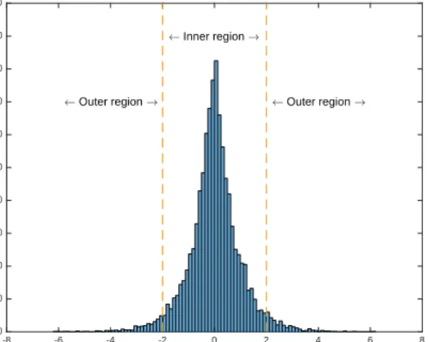
In general, the HS-based RDH algorithms usually consist of three steps. The first step is to generate a histogram from the host signal as shown in Fig. 1. In the context of some sophisticated schemes, a histogram with relatively small entropy is produced from prediction errors. Analogous to the relation between the entropy of source data and the theoretical limit to data compression, the entropy of histogram determines the limit to embedding capacity. The second step is to split the histogram into an inner region and an outer region. The inner region consists of the bins associated with the peak value, whereas the outer region consists of the rest. The final step is to embed message by modifying the inner bins. In order to make room for data embedding, or equivalently to disambiguate the outer bins and the modified inner bins, the outer bins are shifted.
Suppose that we apply the HS technique directly on JPEG quantised coefficients. Typically, the histogram of quantised DCT coefficients resemble a Laplacian distribution centred at
0. In order to maximise the embedding payload, intuitively we would use zero-valued coefficients to carry data. In other words, we set the bin 0 as the inner bin since the value
0 is the peak value. By adding 1 to all the values greater than 0, we empty the bin with value 1. In other words, we shift the outer region on the right-hand side. Then we can embed a binary message by modifying the zero-valued coefficients to the message bits. The message extraction and image restoration processes are simple. The message can be extracted from the coefficients with values 0 and1, whereas
-8 -6 -4 -2 0 2 4 6 8 Value 0 100 200 300 400 500 600 700 800 900 1000 Occurance A Inner region !
A Outer region ! A Outer region !
Fig. 1. Histogram.
the image can be restored by setting every coefficient with value1 to0and shifting back the outer region.
However, modifications to zero-valued coefficients may introduce considerable distortion in the spatial domain because of two reasons. First, a zero-valued coefficient is usually a coefficient that has been heavily quantised. Thus, if a value0
is modified to a value1, the de-quantised value would be much greater than it should be. The other reason is that in general zero-valued coefficients form the majority of coefficients. Hence, the distortion is expected to be severe if say half of the zero-valued coefficients are altered to value1. In addition to this, the size of the compressed file would dramatically increase since RLE is inefficient to compress non-consecutive values.
To avoid the aforementioned problems when applying HS technique on JPEG images, Huanget al. proposed to embed a message into quantised AC coefficients with values1and−1. It is reasonable to choose the values 1 and −1 for carrying message because a sufficient embedding payload would be assured while a certain degree of image quality would be retained. An example of the HS-based embedding process is illustrated in Fig. 2. In this example, we consider a binary message stream (1,1,0,0,0,0,0,0,1)2. The process begins
with a shift in the values greater than1and the values smaller than−1 in order to make room for information hiding. After that, the embedding algorithm modifies the values 1 and−1
according to the message bits. That is, if the message bit is a
1, then1 and−1 are altered correspondingly to2 and−2. If the message bit is a0, then1and−1 remain unchanged.
In contrast to the HS-based method, we propose an ad-justable padding strategy to solve the problems when embed-ding message into zero-valued AC coefficients. The details of our proposed scheme are described in the next section.
III. PROPOSEDSCHEME
In this section, we present the proposed RDH scheme including the embedding, extraction and restoration processes.
A. Embedding Process
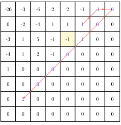
Recall that the value 0 often appears consecutively in a given quantised block. Thus, we can form a ‘zero sequence’ consisting of consecutive zero-valued coefficients by scanning from the bottom right corner in the reversed zigzag order. The length of the zero sequence determines the embedding capacity of the proposed method. However, it is possible, though very unlikely, that the coefficient at the bottom right corner happens to be a non-zero and thus the message fails to be embedded into the block. We mark this non-embeddable case as a special case. By contrast, if the coefficient at the bottom right corner is a 0, or equivalently there is at least one element in the zero sequence, we say it is a regular case.
Before embedding, a binary message is converted into a ternary stream. In order to minimise the distortion caused by the following embedding process, we map the possible digits
0,1and2in the ternary stream to the0,1and−1, respectively. Because the embedding algorithm modifies the value0 to the
-26 -3 -6 2 2 -1 0 0 0 -2 -4 1 1 0 0 0 -3 1 5 -1 -1 0 0 0 -4 1 2 -1 0 0 0 0 1 0 0 0 0 0 0 0 0 0 0 0 0 0 0 0 0 0 0 0 0 0 0 0 0 0 0 0 0 0 0 0
(a) Quantised block
-26 -4 -7 3 3 -1 0 0 0 -3 -5 1 1 0 0 0 -4 1 6 -1 -1 0 0 0 -5 1 3 -1 0 0 0 0 1 0 0 0 0 0 0 0 0 0 0 0 0 0 0 0 0 0 0 0 0 0 0 0 0 0 0 0 0 0 0 0 (b) Histogram shifting -26 -4 -7 3 3 -1 0 0 0 -3 -5 1 1 0 0 0 -4 2 6 -1 -2 0 0 0 -5 1 3 -1 0 0 0 0 2 0 0 0 0 0 0 0 0 0 0 0 0 0 0 0 0 0 0 0 0 0 0 0 0 0 0 0 0 0 0 0 (c) Message embedding Fig. 2. An illustrated example of the HS-based embedding process.
message digits, it is straightforward that the mapping from value 2to−1 reduces the distortion.
According to the length of the message, an integer m is selected as a control parameter for adjusting the embedding capacity. We denote the length of the zero sequence in a quantised block by n and the number of ternary digits to be embedded in a block is given byk=bn/mc.
The embedding process of the proposed scheme is as follows.
1) Convert the binary message stream into a ternary stream and map value2 to−1.
2) Divide the original image into non-overlapping blocks and perform JPEG compression until the quantisation process is completed.
3) Scan the quantised AC coefficients in the reversed zigzag order and stop at the first non-zero elementa in order to form a zero sequence to carry the message.
4) Pad k message digits after a in the zigzag order, or equivalently replace the firstk 0s in the zero sequence with the message digits. If the last digit of the message stream is 0, an indicator is needed to signal the end of embedding. In other words, we need to distinguish the last digit 0 from the 0s after it. In this case, we simply replace the last digit 0 with any value that is impossible to occur if message has been embedded. In order to minimise the embedding impact, the value 2
or −2 is chosen to serve as an indicator. Because of this flexibility in choosing an indicator, we can further embed a binary digit by, say, selecting2 for a message bit 0 and −2 for a message bit −1. Note that there is no need for an extra indicator if the last message digit is a1 or−1since the message digit itself is already an end indicator.
5) Continue the JPEG compression process to encode the coefficients and transmit the marked compressed file as well as the control parameterm to the receiver.
B. Extraction and Restoration Processes
The message extraction and host image restoration precesses are described as follows. First, the receiver performs a de-coding process until the quantised coefficients are obtained. Suppose the receiver knows the length of the original zero sequence n, then the message can be easily extracted from the firstk=bn/mcdigits of the sequence. Hence, we aim at inferringn andk.
Now, the receiver scans the quantised coefficients in the reversed zigzag order and stops at the first non-zero element
b. We denote the length of the scanned zero sequence by n0. Since we know n0 = n−k and k = bn/mc, we derive
k =bn0/(m−1)c. Therefore, the message can be extracted from the firstkbits before b. The restoration process is done by simply setting the last n quantised coefficients to 0. As a result, after the JPEG decompression process, the original JPEG image is revealed.
C. An Instructive Example
An example of the embedding process is illustrated in Fig. 3. It begins with the reversed zigzag scanning on a given quantised block as illustrated in Fig. 3(a). The scanning stops at a non-zero coefficienta=−1and a zero sequence of length
n = 38 is formed to carry the message. In this example, a control parameter m is set to, say, 4. Then we calculate the carrying capacityk=bn/mc=b38/4c= 9.
Assume the first 9 ternary digits of the message are
(1,2,0,0,1,0,0,0,0)3. In order to minimise the embedding
impact, this stream is mapped to (1,−1,0,0,1,0,0,0,0)3.
Since the last digit is 0, we replace it with an indicator 2 or −2depending on the extra digit we want to embed. Supposing that we want to further embed a binary digit0, then we adjust the message stream to (1,−1,0,0,1,0,0,0,2)3 in which the
last digit 2 serves as an end indicator and also represents a ternary message digit 0 plus a binary message digit 0. The embedding process is finished by padding the message stream after the non-zero coefficient as illustrated in Fig. 3(b).
At the receiving end, a quantised block as shown in Fig. 3(b) is produced after few steps of decompression process.
-26 -3 -6 2 2 -1 0 0 0 -2 -4 1 1 0 0 0 -3 1 5 -1 -1 0 0 0 -4 1 2 -1 0 0 0 0 1 0 0 0 0 0 0 0 0 0 0 0 0 0 0 0 0 0 0 0 0 0 0 0 0 0 0 0 0 0 0 0
(a) Before embedding
-26 -3 -6 2 2 -1 -1 0 0 -2 -4 1 1 1 0 0 -3 1 5 -1 -1 1 0 0 -4 1 2 -1 0 0 0 0 1 0 0 0 0 0 0 0 0 0 0 0 0 0 0 0 0 2 0 0 0 0 0 0 0 0 0 0 0 0 0 0 (b) After embedding Fig. 3. An illustrated example of the proposed embedding process.
By following the reversed zigzag path until the first non-zero element b = 2 is encountered, we calculate the length of the consecutive 0s and get n0 = 29. Then the length of the message stream k = bn0/(m−1)c = b29/3c = 9 is derived. Hence, the message stream (1,−1,0,0,1,0,0,0,2)3
can be extracted from the first 9 coefficients before the non-zero element 2.
Since the last digit is a 2, we can extract a bit 0 and restore the ternary digit2to a ternary digit0. Then the stream
(1,−1,0,0,1,0,0,0,0)3 is mapped back to the original
mes-sage stream (1,2,0,0,1,0,0,0,0)3. The original coefficients
as shown in Fig. 3(a) are recovered by setting all the message digits to0. The original JPEG image is revealed after the JPEG decompression is completed.
From the above description, it can be observed that the proposed method is effective but also easy to implement. The performance of the proposed scheme is examined in the next section through the simulated experiments.
IV. EXPERIMENTALRESULTS
In this section, we conduct the simulated experiments to evaluate the performance of the proposed scheme, including the embedding capacity, the visual quality of the marked JPEG image, and the size of the compressed file. The experiments are conducted on six grayscale images as shown in Fig. 4. As reported in [13], the HS-based scheme has been proved to outperform the state-of-the-art methods [14]–[16]. Hence, we evaluate our proposed scheme by comparing with the HS-based scheme only.
The proposed method is tested by setting the control pa-rametermto different numbers:2,3,4and5. In addition, the tests are conducted on the images compressed with different JPEG quality factors: 50 and70. The comparisons are made between the proposed scheme and the HS-based scheme. The embedding capacity is presented in terms of the maximum bits of the embedding payload, whereas the visual quality of the marked image is measured by the peak signal-to-noise ratio (PSNR). The experimental results are shown in Fig. 5 to 10.
It can be observed that our proposed method can achieve better visual quality than the HS-based scheme given the same embedding payload. The underlying reason behind the results is that the proposed embedding algorithm only modifies a small number of coefficients. By contrast, the HS-based scheme shifts nearly every coefficients except for the zero-valued coefficients. Furthermore, the embedding capacity of the proposed method can be freely adjusted and thus it is applicable to different uses and demands depending on how the embedding capacity and the visual quality are balanced.
On the other hand, however, the size of the compressed file of the proposed method is somewhat larger than that of the HS-based scheme on average. The reason for this phenomenon is that the number of non-zero coefficients increases after em-bedding so that the efficiency of run-length encoding (RLE), a component used in JPEG standard, is undermined.
Overall, the experimental results show that the proposed scheme gains significant increase in visual quality at a slight expense of the file size.
(a) Coach (b) Harbour (c) Lena
(d) Locomotive (e) Man (f) Sailboat Fig. 4. Standard test images.
V. CONCLUSION
In this paper, an easy-to-implement RDH scheme for JPEG images with an adjustable embedding capacity is proposed. Observed from the experimental results, the proposed method
outperforms the state-of-the-art in terms of the visual quality since only a small number of zero-valued coefficients are modified. However, the size of the compressed file increases to a slight extend since the modification on the zero-valued coefficients undermine the efficiency of RLE. In data hiding, it is essential to study the tradeoffs between conflicting criteria and establish design principles that approach the theoretical limits. Furthermore, the research on RDH is expected to be developed for various host media and applications in a near future.
ACKNOWLEDGMENT
This work is supported by the EU Horizon 2020 - Marie Sk lodowska-Curie Actions through the project entitled Computer Vision Enabled Multimedia Forensics and People Identifica-tion (Project No. 690907, Acronym: IDENTITY). The au-thors would also like to thank IDENTITY Scientific Advisor, Professor Chin-Chen Chang of Feng Chia University for his invaluable suggestions and advice on this work.
REFERENCES
[1] J. M. Barton, “Method and apparatus for embedding authentication information within digital data,” U.S. Patent 5646997, Jul. 1997. [2] J. Tian, “Reversible data embedding using a difference expansion,” IEEE
Trans. Circuits Syst. Video Technol., vol. 13, no. 8, pp. 890-896, Aug. 2003.
[3] A. M. Alattar, “Reversible watermark using the difference expansion of a generalized integer transform,” IEEE Trans. Image Process., vol. 13, no. 8, pp. 1147-1156, Aug. 2004.
[4] D. M. Thodi and J. J. Rodriguez, “Expansion embedding techniques for reversible watermarking,” IEEE Trans. Image Process., vol. 16, no. 3, pp. 721-730, Mar. 2007.
[5] Z. Ni, Y. Q. Shi, N. Ansari, and S. Wei, “Reversible data hiding,” IEEE Trans. Circuits Syst. Video Technol., vol. 16, no. 3, pp. 354-362, Mar. 2006.
[6] X. Li, B. Li, B. Yang, and T. Zeng, “General framework to histogram-shifting-based reversible data hiding,” IEEE Trans. Image Process., vol. 22, no. 6, pp. 2181-2191, Jun. 2013.
[7] T. Kalker and F. M. J. Willems, “Capacity bounds and constructions for reversible data-hiding,” in Proc. Int. Conf. Digit. Signal Process., vol. 1, pp. 71-76, Jun. 2003.
[8] W. Zhang, B. Chen, and N. Yu, “Improving various reversible data hiding schemes via optimal codes for binary covers,” IEEE Trans. Image Process., vol. 21, no. 6, pp. 2991-3003, Jun. 2012.
[9] X. Zhang, “Reversible data hiding with optimal value transfer,” IEEE Trans. Multimedia, vol. 15, no. 2, pp. 316-325, Feb. 2013.
[10] W. Zhang, X. Hu, X. Li, and N. Yu, “Recursive histogram modification: Establishing equivalency between reversible data hiding and lossless data compression,” IEEE Trans. Image Process., vol. 22, no. 7, pp. 2775-2785, Jul. 2013.
[11] Y. Q. Shi, X. Li, X. Zhang, H. T. Wu and B. Ma, “Reversible data hiding: Advances in the past two decades,” in IEEE Access, vol. 4, no. , pp. 3210-3237, May 2016.
[12] J. Fridrich, M. Goljan, and R. Du, “Lossless data embedding for all image formats,” in Proc. SPIE, pp. 572-583, Apr. 2002.
[13] F. Huang, X. Qu, H. J. Kim, and J. Huang, “Reversible data hiding in JPEG images. ,” IEEE Trans. Circuits Syst. Video Technol., vol. 26, no. 9, pp. 1610-1621, Sep. 2016.
[14] K. Wang, Z. M. Lu, and Y. J. Hu, “A high capacity lossless data hiding scheme for JPEG images,” J. Syst. Softw., vol. 86, no. 7, pp. 1965-1975, Jul. 2013
[15] G. Xuan, Y. Q. Shi, Z. Ni, P. Chai, X. Cui, and X. Tong, “Reversible data hiding for JPEG images based on histogram pairs,” in Proc. Int. Conf. Image Anal. Recognit., Montreal, QC, Canada, pp. 715-727, Aug. 2007.
[16] H. Sakai, M. Kuribayashi, and M. Morii, “Adaptive reversible data hid-ing for JPEG images,” in Proc. Int. Symp. Inf. Theory Appl., Auckland, New Zealand, pp. 1-6, Dec. 2008.
0 0.2 0.4 0.6 0.8 1 1.2 1.4 1.6 1.8 2 x 10⁴ 36 38 40 42 44 46 48 50 52 Payload (Bits) PSNR (dB) QF=50 Proposed (m=2) Proposed (m=3) Proposed (m=4) Proposed (m=5) HS−based 0 0.5 1 1.5 2 2.5 x 10⁴ 36 38 40 42 44 46 48 50 52 54 Payload (Bits) PSNR (dB) QF=70 Proposed (m=2) Proposed (m=3) Proposed (m=4) Proposed (m=5) HS−based
(a) Visual quality
0 0.2 0.4 0.6 0.8 1 1.2 1.4 1.6 1.8 2 x 10⁴ 0 0.5 1 1.5 2 2.5 3x 10 4 Payload (Bits)
Increased File Size (Bits)
QF=50 Proposed (m=2) Proposed (m=3) Proposed (m=4) Proposed (m=5) HS−based 0 0.5 1 1.5 2 2.5 x 10⁴ 0 0.5 1 1.5 2 2.5 3 3.5 4x 10 4 Payload (Bits)
Increased File Size (Bits)
QF=70 Proposed (m=2) Proposed (m=3) Proposed (m=4) Proposed (m=5) HS−based (b) File size Fig. 5. Test results on Coach.
0 0.5 1 1.5 2 2.5 x 10⁴ 34 36 38 40 42 44 46 48 50 52 Payload (Bits) PSNR (dB) QF=50 Proposed (m=2) Proposed (m=3) Proposed (m=4) Proposed (m=5) HS−based 0 0.5 1 1.5 2 2.5 3 x 10⁴ 34 36 38 40 42 44 46 48 50 52 54 Payload (Bits) PSNR (dB) QF=70 Proposed (m=2) Proposed (m=3) Proposed (m=4) Proposed (m=5) HS−based
(a) Visual quality
0 0.5 1 1.5 2 2.5 x 10⁴ 0 0.5 1 1.5 2 2.5 3 3.5 4 4.5x 10 4 Payload (Bits)
Increased File Size (Bits)
QF=50 Proposed (m=2) Proposed (m=3) Proposed (m=4) Proposed (m=5) HS−based 0 0.5 1 1.5 2 2.5 3 x 10⁴ 0 1 2 3 4 5 6x 10 4 Payload (Bits)
Increased File Size (Bits)
QF=70 Proposed (m=2) Proposed (m=3) Proposed (m=4) Proposed (m=5) HS−based (b) File size Fig. 6. Test results on Harbour.
0 0.2 0.4 0.6 0.8 1 1.2 1.4 1.6 1.8 2 x 10⁴ 38 40 42 44 46 48 50 52 54 Payload (Bits) PSNR (dB) QF=50 Proposed (m=2) Proposed (m=3) Proposed (m=4) Proposed (m=5) HS−based 0 0.2 0.4 0.6 0.8 1 1.2 1.4 1.6 1.8 2 x 10⁴ 38 40 42 44 46 48 50 52 54 56 58 Payload (Bits) PSNR (dB) QF=70 Proposed (m=2) Proposed (m=3) Proposed (m=4) Proposed (m=5) HS−based
(a) Visual quality
0 0.4 0.8 1.2 1.6 2 x 10⁴ 0 0.5 1 1.5 2 2.5 3x 10 4 Payload (Bits)
Increased File Size (Bits)
QF=50 Proposed (m=2) Proposed (m=3) Proposed (m=4) Proposed (m=5) HS−based 0 0.2 0.4 0.6 0.8 1 1.2 1.4 1.6 1.8 2 x 10⁴ 0 0.5 1 1.5 2 2.5 3 3.5 4x 10 4 Payload (Bits)
Increased File Size (Bits)
QF=70 Proposed (m=2) Proposed (m=3) Proposed (m=4) Proposed (m=5) HS−based (b) File size Fig. 7. Test results on Lena.
0 0.5 1 1.5 2 2.5 x 10⁴ 34 36 38 40 42 44 46 48 50 52 54 Payload (Bits) PSNR (dB) QF=50 Proposed (m = 2) Proposed (m = 3) Proposed (m = 4) Proposed (m = 5) HS−based 0 0.5 1 1.5 2 2.5 3 x 10⁴ 35 40 45 50 55 60 Payload (Bits) PSNR (dB) QF=70 Proposed (m = 2) Proposed (m = 3) Proposed (m = 4) Proposed (m = 5) HS−based
(a) Visual quality
0 0.5 1 1.5 2 2.5 x 10⁴ 0 0.5 1 1.5 2 2.5 3 3.5 4x 10 4 Payload (Bits)
Increased File Size (Bits)
QF=50 Proposed (m = 2) Proposed (m = 3) Proposed (m = 4) Proposed (m = 5) HS−based 0 0.5 1 1.5 2 2.5 3 x 10⁴ 0 1 2 3 4 5 6x 10 4 Payload (Bits)
Increased File Size (Bits)
QF=70 Proposed (m = 2) Proposed (m = 3) Proposed (m = 4) Proposed (m = 5) HS−based (b) File size
Fig. 8. Test results on Locomotive.
0 0.5 1 1.5 2 2.5 x 10⁴ 34 36 38 40 42 44 46 48 50 52 Payload (Bits) PSNR (dB) QF=50 Proposed (m = 2) Proposed (m = 3) Proposed (m = 4) Proposed (m = 5) HS−based 0 0.5 1 1.5 2 2.5 3 x 10⁴ 34 36 38 40 42 44 46 48 50 52 54 Payload (Bits) PSNR (dB) QF=70 Proposed (m = 2) Proposed (m = 3) Proposed (m = 4) Proposed (m = 5) HS−based
(a) Visual quality
0 0.5 1 1.5 2 2.5 x 10⁴ 0 0.5 1 1.5 2 2.5 3 3.5 4x 10 4 Payload (Bits)
Increased File Size (Bits)
QF=50 Proposed (m = 2) Proposed (m = 3) Proposed (m = 4) Proposed (m = 5) HS−based 0 0.5 1 1.5 2 2.5 3 x 10⁴ 0 1 2 3 4 5 6x 10 4 Payload (Bits)
Increased File Size (Bits)
QF=70 Proposed (m = 2) Proposed (m = 3) Proposed (m = 4) Proposed (m = 5) HS−based (b) File size Fig. 9. Test results on Man.
0 0.2 0.4 0.6 0.8 1 1.2 1.4 1.6 1.8 2 x 10⁴ 38 40 42 44 46 48 50 52 54 Payload (Bits) PSNR (dB) QF=50 Proposed (m=2) Proposed (m=3) Proposed (m=4) Proposed (m=5) HS−based 0 0.2 0.4 0.6 0.8 1 1.2 1.4 1.6 1.8 2 x 10⁴ 38 40 42 44 46 48 50 52 54 56 Payload (Bits) PSNR (dB) QF=70 Proposed (m=2) Proposed (m=3) Proposed (m=4) Proposed (m=5) HS−based
(a) Visual quality
0 0.2 0.4 0.6 0.8 1 1.2 1.4 1.6 1.8 2 x 10⁴ 0 0.5 1 1.5 2 2.5x 10 4 Payload (Bits)
Increased File Size (Bits)
QF=50 Proposed (m=2) Proposed (m=3) Proposed (m=4) Proposed (m=5) HS−based 0 0.2 0.4 0.6 0.8 1 1.2 1.4 1.6 1.8 2 x 10⁴ 0 0.5 1 1.5 2 2.5 3 3.5x 10 4 Payload (Bits)
Increased File Size (Bits)
QF=70 Proposed (m=2) Proposed (m=3) Proposed (m=4) Proposed (m=5) HS−based (b) File size