1 Page 1-18 © MAT Journals 2015. All Rights Reserved
Automatic Dipping System for Vehicles Headlight
Abhishek Vaishnav, Ritesh Kumar NishadMaster of Engineering Bachelor of Engineering
E-mail: [email protected], [email protected]
Abstract
The purpose of our project is to minimizing the problems of road accidents in night. By the using of this system in our vehicles dazzle problem is almost solved. The number of vehicles on our roads is burgeoning day by day. This is turn forced almost all this vehicle manufactures to think about the extra safety instruments and electronic controls to attach with these products for giving the users a safety derived in all road conditions through a mass flow traffic. If asked, one should always mention that the right driving is very cumbersome due to the dazzling light problems and the frequent dipping of headlights by manual means that often causes fatigue to the driver particularly at the time of peak traffic. The auto dipper can perform a great deal in reducing the manual efforts and fatigue of drivers in dipping the headlamp frequently while driving through highways full of moving vehicles. However, vehicles employed with automatic dippers are not very often seen in our cities, and it may be due to lack of information about the system and also because of giving attention to the people saying that it is not at all practicable in our highways.
Keywords: Vehicles, instruments, electronic controls, dazzling light, headlights
INTRODUCTION
The requirement of headlight is very common during night travel. The same headlight which assists the driver for better vision during night travel is also responsible for many accidents that are being caused. The driver has the control of the headlight which can be switched from
high beam (bright) to low beam (dim). The headlight has to be adjusted according to the light requirement by the driver. During pitch black conditions where there are no other sources of light, high beam is used to. On all other cases, low beam is preferred. But in a two-way traffic, there are vehicles plying on both sides of the
2 Page 1-18 © MAT Journals 2015. All Rights Reserved road. So when the bright light from the
headlight of a vehicle coming from the opposite direction falls on a person, it glares him for a certain amount of time. This causes disorientation to that driver. This discomfort will result in involuntary closing of the driver’s eyes momentarily. This fraction of distraction is the prime cause of many road accidents. The prototype that is has been designed, reduces this problem by actually dimming down the bright headlight of our vehicle to low beam automatically when it senses a vehicle at close proximity approaching from the other direction. The entire working of the dimmer is a simple electronic circuitry arrangement which senses and switches the headlight according to the conditions required.
Electronic controls to attach with these products for giving the users a safety derived in all road conditions through mass flow traffic. If asked, one should always mention that the right driving is very cumbersome due to the dazzling light problems and the frequent dipping of headlights by manual means that often causes fatigue to the driver particularly at the time of peak traffic. So, naturally to get rid of this perennial problem, an automatic mechanism has to come up to dip the headlamp automatically whenever
required. For keeping a motor vehicle under perfect control and reins of the driver, different types of controls and accessories are provided in an automobile around the driver, seat, on the dashboard and at the footboard. Simply, an automatic dipper is a unit, which can automatically judge when the headlight beam needs to be lowered, and which dip the headlamp from which beam to a dipped beam.
As the dipper unit is well connected to the lighting system of the vehicle, we have to look short into the type and construction of a head light before discussing the wiring diagram or the construction of Automatic dippers. You must have come across this irritating situation while driving at night when you find the headlight focus from an opposite vehicle falling straight in your eyes, making things difficult to assess. Incidentally, the driver of the opposite vehicle might be going through the same situation due to the headlight focus from your vehicle. Such situations are normally tackled by using manual dipper switch mechanism, where the driver is prompted to "dip" the focus of his headlight, thus giving the opposite vehicle a chance to adjust his vehicle and also an indication that he too needs to "dip" his vehicle lamps.
3 Page 1-18 © MAT Journals 2015. All Rights Reserved The modern lighting system consists of
switches, lamps, wiring harness, and fuses or circuit breakers. But the provision should also be made that the drivers of other vehicles coming from the opposite direction to not experience a glare. For this purpose, a dipped or meeting beam is also provided for maintaining the reasonable speed with safety without dazzling the coming driver. To prevent dazzle to the oncoming driver during particularly misty or hazy conditions the light about the horizontal should be cut off. This is called dipping of the head light beam. In an average car, the lighting system consumes about 70 a 75% of electrical energy when driven at night. In terms of amperage the consumption may be from 24 a 40 A at night for al purposes including the radio, heater, and transmission controls.
There are two kinds of light sources, namely, the one that emits light and the other that reflects light. In the case of headlamp used in automobiles, both the things are combines in one. The filament of the electric lamp is the primary source, while the reflector is referred to as the secondary source.
The headlight is composed of three elements:
1. The light filament that gives off light when a current flows through it.
2. The parabolic reflector that reflect the light in front.
3. The lens that refracts of distorts the light beam into an illuminating pattern.
THE CONCEPT OF AUTO DIPPING In an automobile headlight, a 'meeting' beam (dip beam) is provided in addition to the driving beam (high beam) so as to reduce the dazzle for those approaching head-on to the vehicle. The Auto Dipping Device for a head light is intended to automatically change the Headlight Circuit to either driving beam or dip beam given a particular set of road conditions, without the intervention of the driver. The present practice is to operate the dip switch manually.
The function of the headlight is to illuminate the road ahead of the automobile so as to reveal objects ahead from a safe distance; at the same time it should cause minimum discomfort and glare for drivers coming from the opposite side. The most extensively used and universally accepted anti-dazzle arrangement is the bifocal or double filament bulb. These bulbs have two filaments in which one filament is positioned in relation to the reflector to
4 Page 1-18 © MAT Journals 2015. All Rights Reserved give the main forward beam, while the
other filament gives the dipped beam. The driver controls this system; either by a foot operated switch or by a switch mounted on the steering column.
PROBLEM ASSOCIATED WITH
MANUAL DIPPING
Manual dipping is not being done satisfactorily in India due to a variety of reasons, which includes sheer physical strain involved in operation of the dipper switch hundreds of times every night. (The total for a single night will be 1000 if we consider 8 hours of travelling and one encounter every one-minute and could exceed this number if one travels on roads with dense traffic). The other reason includes a general tendency of paying more attention to steering control at the cost of dipping during a critical vehicle meeting situation especially in the case of heavy loaded vehicles. More reasons are the physiological and psychological state of a driver, which is influenced by a variety of factors like working hours, economic issues and social factors etc. Another major cause is 'ego problem', which makes each one wait till the other person initiates dipping, which may not happen.
STUDIES ON DIPPING PRACTICES ON INDIAN ROADS
A study carried out by Central Road Research Institute, New Delhi, (Road Research Paper No. 216), reveals the poor state of affairs on the Indian roads, regarding dipping. The observations and recommendations of the study group on road safety constituted by the Government of India vide Resolution No.19T (14) 68, dated June 3, 1969, is as follows:
NIGHT DRIVING
"A frequent cause of accidents at nights is the glare caused by oncoming vehicles which momentarily blinds the driver's vision. It takes three to eight seconds for a person with good eyesight to recover from the glare and during this time the vehicle will have covered a long distance in utter darkness and it will be sheer luck if it escapes an accident. A glare recovery test should be carried out to gauge the applicant's ability in this direction, followed by tests pertaining a color and night blindness".
DRIVING AT NIGHT WITH MAIN BEAM OF HEADLIGHT ON "This is one of the common failings of our drivers in night driving, specially on dark or badly lit roads that we generally have in rural areas and also along many of the
5 Page 1-18 © MAT Journals 2015. All Rights Reserved roads in our cities and towns. Driving
courtesy imposes a special responsibility on the driver, that the oncoming driver is not handicapped by the dazzle of headlights. To avoid this, it is imperative that as the vehicles approach from opposite directions, the main beams should be switched OFF and the dipped beams used instead, so that the two vehicles can pass each other safely. Country to the above requirement, many of our heavy vehicle drivers are given to the practice of blinding oncoming vehicles drivers by using both the main and dipped beams of their headlights simultaneously, to gain on advantage over the oncoming driver." While the above refers to the culture of road users, the road situation itself is disheartening in our country. The highways in developed countries are mostly of 6 lanes divided type, meeting very good geometrical requirements so as to minimize glare whereas in India only 1.48% of the total length of National Highway is of the standard multi-lane type
THE OBSERVATION OF THE
STUDY GROUP ON ROAD SAFETY (CONSTITUTED BY GOVERNMENT OF INDIA VIDE RESOLUTION NO. 19 (14) 68, JUNE 3 1996) REGARDING
THE CONDITION OF OUR
NATIONAL HIGHWAYS IS
"The Indian roads are all essentially very narrow, tortuous in their alignment and suffer from many inadequacies, vis-à-vis the present day motor traffic which has registered a phenomenal increase during the post-Independence period. The other conditions of the roads like poor shoulders, narrow culverts and bridges, sharp and numerous curves and steep gradients which limit the sight distance, numerous low level causeways and submersible bridges are perennial hazards. All the above tell on the nerves of the driver, causing fatigue and leading to errors and misjudgment while driving. All the above indicate the importance of dipping of headlights in a country like India, so as to avoid the problem of glare which impairs the visibility which is vital for safe driving in a meeting situation during the night. This leads to the conclusion that an Auto Dipping Device can go a long way towards safety enhancement.
DRIVING VISION AND GLARE The human eye, one of the most complex organs and the greatest gift of nature, is equipped with a variety of adaptation abilities. However, it is incapacitated by glare. The human eye's inability to refuse glare sources in the normal visual field (the sun does not fall in the normal visual
6 Page 1-18 © MAT Journals 2015. All Rights Reserved field) during the long evolution process
might be because nature was unaware of man's potential to create disabling sources-the most serious of which is vehicle headlight glare. The visibility of an object is determined by many factors apart from background luminance.
Mere reduction of background luminance by an auto dipper in a particular situation need not necessarily result in clear perception of the objects on the road through visual information. The physical dimensions of the object, the luminance reaching the object, its reflectance factor, its color contrast, its time constancy, its movement in space, etc. determine the nature and quantum of visual information available. The actual perception is dependent on the physical condition and the perception method of the viewer. The headlight systems of the vehicle, including the number and type of lamps, their alignment and their efficiency, all play a vital role in influencing the visibility of objects on the road.
Fig. 1(a, b): Glare in Highway.
HEADLIGHT DAZZLE
The dazzle effect is one of the major problems faced by a driver in night driving. So one has to stop the high intensity light from the eyes of the incoming driver or road users to prevent the dazzle effect. Automatic Dipper is one such mechanism, which is employed for safety night driving without the intense dazzling effects. Without much efforts from the driver which otherwise has to dim the lights every seconds by manual means may lead to fatigue to the driver especially during peak traffics. So it will be better to know Elwha is meant by dazzle and Elwha all devices are often used in preventing dazzle effect before mentioning the advantages and uses of an auto dipper. The problem of headlight dazzle is linked with many factors of which, the human eyes is the most important. In fact, it is the final judge in respect of dazzle and illumination. It may be mentioned that for driving, bright illumination is essential. In short,
7 Page 1-18 © MAT Journals 2015. All Rights Reserved condition of illumination, should be such
that there is clear vision for all motorists. Dazzle is nothing but brightness, which causes interference with vision. The various factors, which govern it, are: brightness, contrast, and the angle subtended by the bright area on the eye. It is the contrast between the bright and dark areas, which is one of the main causes of dazzle. However, it is difficult to lie down in terms of quantity the fixed ratio of the brightness of the two areas which is likely to produce or eliminate the effect of dazzle since it is controlled by the brightness of the lighter of the two areas. The ratio between the absolute black area and a dimly lit area may be quite great but there will be no dazzle effect. Further, an intensity bright area with very dark surroundings, does not give a dazzling.
PROBLEM IDENTIFICATION Current Problem Faced by Motorists Motorists are facing a huge problem due to this high beam light which falls directly onto their eyes during driving. There are many medical facts and figures which support their problems of night driving.
Troxler Effect
In the medical world, Troxler effect is used to describe a kind of temporary blindness. It is otherwise known as the
‘fading effect’. A study shows that if our eyes are exposed to a very bright light source of around 10,000 lumens, we experience a glare [1–5]. This glare is produced due to over exposure of the rods and cones inside our eye. Even after the source of glare is removed, an after-image remains in our eye that creates a blind spot. This phenomenon is called Troxler effect. This means that the driver’s reaction time is increased by 1.4 seconds. For example, let us assume a motorist travelling at 60 Miles per hour takes 0.5 seconds to react to a hazard and will stop within 41 feet. Due to Troxler effect, the same person travelling under the same conditions will take 0.9 seconds longer to react and hence will come to a complete halt only at 123 feet [2–7]. There is a huge difference of 82 feet. This is more than enough to cause a disaster on the road. This Troxler effect is across all ages. Any one exposed to sudden bright light experiences this Troxler effect.
Accidents due to Troxler Effect
As discussed earlier, there are many accidents caused due to Troxler effect. Many accident reports have been witnessed where a large vehicle, hitting a slow moving smaller vehicle while the latter is trying to over-take. Though it might be obvious to blame the driver, they
8 Page 1-18 © MAT Journals 2015. All Rights Reserved claim to have not seen the smaller vehicle
approaching. This is the most common example of illustrating the Troxler effect in our day-to-day life. Due to excessive brightness, the driver of the large vehicle is blinded. So, he is unable to notice the smaller vehicle even though it is right in front of him [8–11]. This can be avoided if the headlight is dipped to low beam mode. According to Forbes, the statistics shown in Figure 2 gives the details of the accidents that had occurred in the year 2013 in Asia due to over-bright light. It shows clearly that India tops the list. Hence, this becomes the major concern to think of a new innovative solution that is useful and also cost effective. This had led to the development of the automatic headlight dimmer prototype.
Fig. 2: Accident Report of Asia due to Troxler Effect in 2013.
MEHODOLOGY The Headlight Beams
The headlight of vehicles is fitted with two bulbs. One bulb is used for high beam and the other for the low beam. On an average, in India, the requirement of the headlight is essential from 6.00 pm till 5.00 am. It is most essential during late night travels. The headlight can be switched between the bright and dip modes by the driver using a switch. The bright mode is used when there are no other sources of light on the streets to aid with driving. Long highways, a pitch black street with no lights are the ideal locations where one would use a bright beam. The dip or the low beam is less intense than the bright beam. It is used under normal night driving conditions. The dip beam is aimed low at the road and gives less range. The high beam has a longer range but very less field coverage. Hence, dip beam is less intense (700 lumens) and high beam has a higher brightness index (1200 lumens) when tested under a standard distance of 50 feet from the vehicle. Figure 3 shows the range of the low beam and the high beam. The high beam since has a longer throw and a higher brightness index, will ultimately fall directly on the eyes of the driver coming on the other side of the traffic. Figure 3 Range of low beam bulb (a) and high beam bulb (b) of a car the angle of
9 Page 1-18 © MAT Journals 2015. All Rights Reserved spread of the dip beam and the high beam
is 135 and 15 respectively. This again confirms on their range and spread. A human eye can withstand a brightness of around 1000 lumens when the source is at 20 feet. Hence it is very important to make sure that our vehicle’s bright (high) beam does not affect the driver coming from the opposite direction. As it is not possible to reduce the intensity of our headlight, all we have to do is to switch down to the dip beam until the traffic has passed away. This will ensure a safe and a friendly
driving on the road during the night.
Fig. 3: Range of Low Beam Bulb (a) High Beam Bulb (b) of a Car.
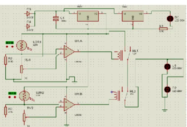
The Prototype Circuit The Layout
The circuit is a simple assembly of commonly used circuit components. The layout is shown in Figure 3. The components have been chosen with utmost care and accuracy so as to keep the design simple and easy to implement.
Components Used
The various components used in the circuit are LDR (light dependent Resistor), two resistors as a potential divider, Transistor, Relay switch, LED bulbs and a Supply voltage. The LDR is used to sense the incoming light. As the name suggests, its resistance value will vary according to the intensity of light that is incident upon its sensor. Higher the light intensity, lower will be its resistance. The resistors used are a standard 0.25 watt, 1.6 kilo ohm and 30 ohm. They are used a potential divider in order to control the gate current to the transistor. To sense a wider range of light intensities, a POT can be used. The transistor can be a BJT (bipolar junction transistor) or a MOSFET (metal oxide field effect transistor). If BJT is used, then the standard BC 547 is preferred. If a higher switching speed is required, then MOSFET –IRF 840 can be used. The relay used is a 400 ohm coil, 12 Volt, 5 terminal types. The normally-open contact is connected to the low beam bulb of the vehicle while the normally-closed contact is connected to the high beam bulb. A supply of 12 volts is required for the circuit. It is taken from the vehicle’s battery box. This is preferred for two reasons. First, it is a constant DC supply and second, there is no need for introducing a separate electrical supply
10 Page 1-18 © MAT Journals 2015. All Rights Reserved source. Two 0.25 watt LED bulbs are
taken for simulating the headlights of the vehicle. One represents the bright mode bulb and the other, the low beam bulb.
Principle of Operation
From the layout, the basic idea about the working of the circuit can be understood. The LDR acts as variable resistor. So the LDR, the two resistors form a potential divider network which will decide the current in the circuit.
Thus, this balanced network gives a trigger to the gate/base of the transistor. The design of this particular circuit gets a trigger if there is a voltage imbalance in the circuit due to change in resistance of the LDR due to the light source. The basic operation is like that of a comparator. The transistor’s output is connected to the relay coil.
The bulbs are already connected to the relay contacts as mentioned earlier. LED 1 represents the high beam bulb which is in normally closed (NC) condition with the relay. LED 2 represents the low beam bulb of the vehicle which is at the normally open terminal (NO) of the relay. Whenever a high-intense light falls on the LDR, it is resistance drops thus creating an unbalance in the potential divider formed
between the LDR, and two resistors R1 and R2. This will create a trigger current which turns on the transistor BC 547. The transistor gets into conduction mode and switches the relay. Hence the NC terminal will get disconnected and NO terminal will be switched. So, the vehicle’s headlight which is in bright mode (LED 1) gets turned off and the low beam mode (LED 2) gets turned on by the relay. This happens when the vehicle from the opposite side crosses our vehicle.
Thus as the other vehicle comes nearer, the intensity of that beam will increase and will hence switch our high beam light to low beam. As it moves away, the LDR will be turned away from the moving vehicle. So, the LDR resistance increases and the bridge balance. There will hence be no trigger current and the relay switches back to its normal position. This will again turn on the bright beam mode bulb in our vehicle.
11 Page 1-18 © MAT Journals 2015. All Rights Reserved Fig. 5: The Actual Circuit.
Working of the Circuit
Based on the prototype, an actual working model of the same circuit has been constructed. The exact same components have been used in its construction. The source required is a 12 V DC supply. We have taken the DC source from battery. But in real-time application, this can be substituted from the car’s own battery pack. The headlights, LDR, transistor are all connected to the same DC supply. For its working, we need to simulate the condition where the LDR is exposed to a bright light, which is actually the headlight of another vehicle coming from the opposite side. Thus the LDR has a change in resistance. Under normal conditions, the vehicle is using high beam bulb (shown as red LED in This case is considered under normal ideal conditions. At this stage, the relay is in NC condition. To understand the real-time working of this circuit, a high intense flash light has been used to simulate the event of an approaching
vehicle. Whenever, the LDR senses a light, it has to automatically switch from the high beam mode to the low beam mode. So, till the LDR senses the bright light (approaching vehicle), the bright bulb will be ON (RED LED). Once the intensity of the incident light goes beyond a particular value, it means that the vehicle is in close proximity of our vehicle. The LDR senses this threshold level and a drop in resistance are observed. This will send the transistor into conduction and the relay switches its contacts. Hence, the NO contact which is connected to the low beam bulb gets turned ON. As the relay is switched, the NC terminal is turned OFF. Thus the low beam light is switched ON automatically (shown by BLUE LED in Figure). The left side of the figure is illuminated by a flash light to simulate the presence of an approaching vehicle.
The Implementation
The circuit had been constructed and proved to be working model. There are a few criteria which need to be addressed while placing this device in a real vehicle.
They are:
It should be kept at a safe place, protecting from external environment like rain and dust.
12 Page 1-18 © MAT Journals 2015. All Rights Reserved The placement of this circuit should be
in line with the eye of the driver, so that it responds exactly in the same way how a driver would react to the bright light.
The circuit should have a constant supply whenever the headlights are turned ON.
It should be compact and easy to install. This device should be place in all the vehicles.
By installing this device, each vehicle can independently operate on its own. Until the vehicle is encountered by an opposite vehicle, it can travel with high beam. Once it encounters an opposite vehicle, each of the two vehicles senses the opposite vehicle’s light. Thus, if either of the vehicles is using high beam, it switches to low beam. If the headlight is already in low beam, then no change occurs. As the vehicles cross each other, the intensity of light falling on the sensor decreases and the headlights switches back to their original mode. There might be a question of other sources of light in the road like sign boards, street lights and buildings. But as LDR is used as the source and the placement of the device is highly directional, it is not affected by any of other light sources which might be present
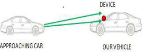
in vicinity. Moreover, the light from the vehicle’s headlamp is of a distinct nature. The maximum spread angle of the headlight is 135 only. The other sources will be located far away from the road and hence their spread angle will be very high. Hence by the time the spread light from other sources reach the sensor its intensity will be very much reduced below the triggering threshold level. From the above discussions, it has been concluded that the device can be concealed in front of the car, near the wipers, at the base of the windscreen (Figure 6). The device is denoted as a red dot. This is the ideal place as it mimics the driver’s line of sight and also safe from environmental factors and accidents.
Fig. 6: Positioning the Device in Vehicle.
Positioning the device in vehicle in the circuit, by using suitable adjustable resistors, we can tune the circuit’s sensitivity to our requirement. It can be made sensitive for a wide range of light beam by just varying the balance condition
13 Page 1-18 © MAT Journals 2015. All Rights Reserved of the potential divider network. Hence,
the driver can manually adjust the sensitivity level so that it can be customized for his personal driving comfort.
The Human Eye and its Sensitivity
The human eye is a very sensitive organ. It works almost an entire day without any rest. Our eyes are adaptable for a Particular range of vision. We have two visions namely the scotopic and photopic vision. Our eyes actually behave differently in different conditions. During bright surroundings, our eyes can resist up to 3 cd/m2. This is the photopic vision. During dark and unlit conditions, our eye switches to scotopic vision which has a range of 30-45 μcd/m2. It takes 4 seconds for our eyes to change from photopic vision to scotopic vision. This is also an example of Troxler effect. As the brightness increases, the strain to focus on an object increases. This will increase the response time of that person. Figure show that as the luminous index increases, the reflection percentage increases logarithmically. Higher the reflection index, lesser is the ability to perceive image in the eyes. This shows the variation of eye response to different luminosity and brightness. The normal range, adaptable range and the glare limits
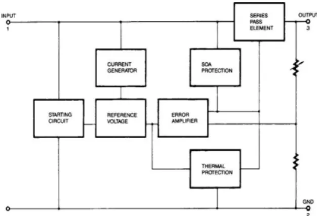
are shown. Thus, at the glare limit, the brightness and luminosity are maximum. Above the glare limit, the human eye is forced to close to avoid exposure to excessive light. HARDWARE COMPONENTS 1. Transformer (230–12 v ac) 2. Voltage Regulator 3. Rectifier 4. Filter 5. Microcontroller (at89s52/at89c51) 6. Relay Driver 7. Push Buttons 8. LCD 9. LED 10. 1n4007 / 1n4148 11. Resistor 12. Capacitor
14 Page 1-18 © MAT Journals 2015. All Rights Reserved Project Block Diagram
RESULTS AND DISCUSSION
Truly speaking, auto dippers are devices, which will attain more and more importance in the forthcoming years. In short, it is a device with a very bright future. The number of vehicles and the condition of the roads are improving very fast and the day is near, when the driving
regulation, nature of traffic etc., are growing up to the levels which is already there in countries like America who successfully using auto dippers in their highways. Auto dipper is a highly sophisticated electronic device which can automatically judge when the head light beam needs to be lowered. Auto dippers are basically switches, which dip the headlamp from high beam to a dipped beam if a certain amount of light falls on its sensor. This is a system, which electronically selects the proper headlamp beam for smooth driving. It switches headlights of own vehicle to Dipper Mode (Low Beam) automatically when the sharp High beam lights of an upcoming vehicle falls on its sensor and switches back from Dipper Mode (Low Beam) to main Mode (High Beam) automatically once the upcoming vehicle passes off and vice versa. It all happens within a fraction of second. Apart From this, Auto dipper also keeps high beams under control automatically in well lit streets.
The following results are obtained:- 1. It reduces the chances of accidents at
night.
2. Provide extra safety to driver at night. 3. Increases safety during night.
4. Problem of glare almost overcome. 5. Problem of dazzle is also almost
15 Page 1-18 © MAT Journals 2015. All Rights Reserved Automatic dipper performs it is
function of automatic dipping of head light beam and restoring of head light beam very efficiently. Beside this the automatic dipping device also gives the cyclic overtaking signal very efficiently.
Automatic dipper has the efficiency to dip the head light beam of the vehicle in which it is fitted even when the oncoming vehicle is 180 m away which is two times more than the stopping distance (80 m) required at 60 km/h.
Automatic dipper not only dips the headlight beam but also restores the main beam in case the countering vehicle does not dip the head light beam within the safe distance of 60 m before crossing each other. This promotes road safety at night time driving.
Automatic dipper does not get activated by street lights (mercury/sodium) or by any stray light.
When both the vehicles were fitted with Automatic dipper then both the vehicles dips the head light beam of each other efficiently. This will promote road safety during night time.
The majority of driver’s when interviewed are of opinion that glare is a problem during night time driving and majority of them felt discomfort, irritation and reduction in driving performance due to glare during night time driving.
The majority drivers who have used automatic dipper when interviewed were of opinion that the use of automatic dipper provided them comfort and relaxation from glare and also in improve the driving performance during night time.
The majority of the drivers are also of the opinion that the automatic dipper should be fitted in all the vehicles. The automatic dipping of head light
beam and it is restoring within the stopping distance plus the other functions available on automatic dipper system fulfils driving requirements necessary for night time driving, which are likely to aid and to promote road safety during night time.
APPLICATIONS
As the automatic dipper is particularly designed and good for the high way driving, but the vehicle is meant for all type of roads, and for facing some particular situation where the driver needs
16 Page 1-18 © MAT Journals 2015. All Rights Reserved more light to see by etc., manual override
is also fitted with the automatic dipper unit by which the driver can operate the heedful becomes manually leaving out the auto system inoperative. The driver has a sensitivity control, which allows adjustment of the system to the surrounding light. The override system can be used when the oncoming driver does not dim, the driver needs more light to see by and also on rural road where not much vehicles are there at night. Auto dipper is a highly sophisticated electronic device which can automatically judge when the head light beam needs to be lowered. Auto dippers are basically switches, which dip the headlamp from high beam to a dipped beam if a certain amount of light falls on its sensor. This is a system, which electronically selects the proper headlamp beam for smooth driving. It switches headlights of own vehicle to Dipper Mode (Low Beam) automatically when the sharp High beam lights of an upcoming vehicle falls on its sensor and switches back from Dipper Mode (Low Beam) to main Mode (High Beam) automatically once the upcoming vehicle passes off and vice versa. It all happens within a fraction of second. Apart From this, Auto dipper also keeps high beams under control automatically in well lit streets.
CONCLUSION
Newer and better technologies always come with time and it will help in reducing the manual labor and difficulties in the sectors where it is made use. And in our case, the auto dipper can perform a great deal in reducing the manual efforts and fatigue of drivers in dipping the headlamp frequently while driving through highways full of moving vehicles. However, vehicles employed with automatic dippers are not very often seen in our cities and it may be due to lack of information about the system and also because of giving attention to the people saying that it is not at all practicable in our highways. Yes, of course it has got some drawbacks like that one which is most common, when we drive the vehicle fitted with automatic dippers on a road in which different types of vehicles and hence varying light intensities cause frequent flickering of the headlight. And also the operation of the system eliminated or reduced by devising newer methods and technologies. The one nowadays available is only useful in highways and straight width roads. Truly speaking, auto dippers are devices, which will attain more and more importance in the forthcoming years. In short, it is a device with a very bright future. The number of vehicles and the condition of the roads are improving very
17 Page 1-18 © MAT Journals 2015. All Rights Reserved fast and the day is near, when the driving
regulation, nature of traffic etc., are growing up to the levels which is already there in countries like America who successfully using auto dippers in their highways.
An auto dipper could play a crucial role in shifting the headlights from driving beam to meeting beam and vice versa. This will improve visibility by minimizing glare, a major cause of momentary loss of vision. The realization of the ultimate goal of total road safety through creating ideal visibility conditions is dependent on efforts in all other related areas mentioned above. Glare during driving is a serious problem for drivers. This is caused due to the sudden exposure of our eyes to a very bright light; the bright headlights of vehicles in this case. This causes a temporary blindness called the Troxler effect. Eventually, this becomes the major reason for night accidents. The driver should actually turn down the bright lights immediately to avoid glare to the other person which is not happening. Hence, is the idea for the design and development of a prototype circuit called the automatic headlight dimmer. It gives the driver to use high beam light when required. But is automatically switches the headlight to low beam when it senses a vehicle
approaching from the opposite side. The circuit consists of simple and economical components which can be easily installed. The working and implementation of the prototype are discussed in detail. The effects of bright light on the human eye are also studied. Thus, the implementation of this device in every vehicle in future will not only avoid accidents but also provide a safe and a comfortable driving.
AUTOMATIC LIGHTS OFF AND ON It is very important thing which we have added to our project is that headlights automatically on at the time of night and it will be automatically off at the time of day, since many people forget to turn off lights at the morning and the drive there vehicles with headlight on and many drivers due to fatigue not turn off light since it consume battery power and by this terminology we can stop this.
The main importances of this additional system are below:-
1. It increases efficiency of battery. 2. Due to lights on in a day it may be
problematic to other.
3. It not only save our battery but also reduces effort of driver.
4. By installing this system driver do not has any need to remember about headlights on and off.
18 Page 1-18 © MAT Journals 2015. All Rights Reserved FUTURE SCOPE
It can also improved by deciding it is not to affect by street lights and other light, it is not very successful in India but in future all the car manufacturer company may think about it for install in all the vehicles our central government with Punjab government tries to use this in 2004 and it was not too successful. The cost of this system is across 5000–7000 per vehicles and its life is almost 10 years and it can reduces the problem of road accidents at night due to dazzling of light and problem of glare. An auto dipper could play a crucial role in shifting the headlights from driving beam to meeting beam and vice versa. This will improve visibility by minimizing glare, a major cause of momentary loss of vision. The realization of the ultimate goal of total road safety through creating ideal visibility conditions is dependent on efforts in all other related areas mentioned above.
REFERENCES
1. C. Susana Martinez, S.L.Macknik, D.H.Hubel The role of fixational eye movements in visual perception.
Nature Reviews Neuroscience. 2004; 5: 229–240P.
2. Ryota Kanai, Yukiyasu Kamitani, Universiteit Utrecht. Time-locked
perceptual fading Induced by visual Transients. Unpublished.
3. S. Aishwarya. Bright Headlights a major cause of accidents. The Hindu, Online Edn; 2006.
4. C. Guttman. High intensity headlights could cause road accidents by dazzling oncoming drivers. Eurotimes; 2003. 5. J. J. Fazzalaro. Limitations on
Headlight brightness. OLD Research Report. 2003; 87(1): 113–117p.
6. S.T.Chrysler, P.J.Carlson, H.Gene Hawkins. Imapcts of Retro reflectivity on sign management. 2003.
7. Lighting the future standard and high performance automotive halogen bulbs-Hella.
8. A.Majumder, S.Irani. Contrast enhancement of images using human contrast sensitivity.
9. A.B.Watson, Temporal sensitivity.
Vision RPS. 1969; 9: 947–952p.
10.R.Shapley, E.Kaplan, K.Purpura. Contrast sensitivity and light adaptation in photoreceptors or in the retinal network; 1993.
11.A.T.Bahill. Development, validation and sensitivity analyses of human eye movement models. 1980; 311- 357p.