FAULT DETECTION IN THREE PHASE INDUCTION MOTOR USING ARTIFICIAL INTELLIGENCE
UNIDA IZWANI BINTI MD DUN
This thesis is submitted as partial fulfillment of the requirements for the award of the Bachelor of Electrical Engineering (Power System)
Faculty of Electrical & Electronics Engineering University Malaysia Pahang
ii
“All the trademark and copyrights use here in are property of their respective owner. References of information from other sources are quoted accordingly, otherwise the information presented in this report is solely work of the author”.
Signature : ____________________________ Author : UNIDA IZWANI BINTI MD DUN Date : 30 NOVEMBER 2010
iii
DEDICATIONS
Specially dedicated to My beloved father and mother,
To my siblings and friends
iv
ACKNOWLEDGEMENT
Thanks to Allah for giving me a good health to complete my final project. This project would not have been possible without the support of many people. I would like to thanks my supervisor Dr. Ahmed N Abdul Alla who was abundantly helpful and offered invaluable assistance, support and guidance. Deepest gratitude are also due to laboratory assistance without whose knowledge and assistance this project would not have been successful.
Special thanks also to my beloved friends for sharing any information with me and giving me moral support to finish up this project. Not forgetting the Ministry and Faculty of Electrical and Electronics for providing the financial means and laboratory facilities.
I also want to express my love especially for my parents for their understanding and endless love through the duration of my studies.
Once again, thank you all very much from the bottom of my heart. Without you, I could never have done it successfully.
v
ABSTRACT
Artificial intelligence (AI) techniques have proved their ability in detection of incipient faults in electrical machines. In this project, the fault diagnosis of three phase induction motors is studied detailed in unbalance voltage and stator inter turn fault using simulation models and neural networks have been used to train the data using Radial Basis Function Neural Network (RBFNN) in MATLAB with Graphical User Interface Development Environment (GUIDE) structured. Nowadays artificial intelligence is implemented to improve traditional techniques. The results can be obtained instantaneously after it analyzes the input data of the motor. The increased in demand has greatly improved the approach of fault detection in polyphase induction motor. Data is taken from the experiment checking the induction motor fault and is simulated into MATLAB using RBFNN. The first stage is to collect the data by experimental and simulating a Simulink model using MATLAB. Three Simulink model will be created where each of the model represent the motor condition. The result of the simulation will then be the data used to create an ANN.The second stage creates and trains an ANN. From the data obtained during the first section, a target output will determine the motor condition whether the motor is in a healthy state or fault occurred. In the third stage the development Graphical User Interface (GUI) is carried out this system. The GUI is developed by using MATLAB for the purpose of evaluating and testing the ANN. The purpose of this final year project, the development of Fault Detection in Three-Phase Induction Motor Using Artificial Intelligence is to satisfy the increased in demand to improve the approach of fault detection in polyphase induction motor. Artificial intelligence is implemented to improve traditional techniques, as the results can be obtained instantaneously after it analyzes the input data of the motor where it can be accomplished without an expert.
vi
ABSTRAK
Teknik inteligensi buatan (AI) telah membuktikan keupayaan untuk mengenalpasti kerosakan mesin elektrik pada peringkat awal. Di dalam projek ini, kerosakkan pada tiga fasa motor induksi didiagnosis lebih kepada ketidakstabilan voltan dan kerosakkan pada lilitan stator dengan menggunakan model simulasi dan rangkaian neural digunakan untuk melatih data dengan menggunakan rangkaian neural dasar fungsi susunan lingkaran (RBFNN) di dalam MATLAB dengan struktur persekitaran pembangunan grafik perantaramuka pengguna (GUIDE). Pada masa kini, inteligensi buatan (AI) telah dipraktikkan untuk mengatasi teknik tradisional. Keputusan boleh didapati selepas ia menganalisis data-data motor tersebut. Permintaan yg semakin meningkat telah membaiki cara mengenalpasti kerosakkan pada motor induksi tiga fasa. Data yang diambil daripada ujian mengenalpasti akan disimulasikan menggunakan RBFNN di dalam MATLAB. Langkah pertama adalah untuk mengutip data yang telah dihasilkan daripada simulasi menggunakan Simulink di dalam MATLAB. Tiga model Simulink akan di cipta dimana setiap model mewakili setiap kondisi motor. Keputusan daripada simulasi akan digunakan sebagai data untuk mencipta ANN. Langkah kedua adalah untuk melatih ANN tersebut. Maklumat yang telah didapati dalam langkah pertama, sasarannya adalah untuk mengenalpasti sama ada motor dalam keadaan yang baik ataupun mengalami kerosakkan. Pada langkah yang ketiga pula, pembangunan perantaramuka dengan pengguna (GUI) direka. GUI ini dibangunkan menggunakan MATLAB bertujuan untuk menguji dan menjana data-data daripada ANN. Tujuan projek tahun akhir ini, adalah untuk mengenalpasti kerosakan di dalam motor induksi tiga fasa menggunakan teknik inteligensi buatan (AI) adalah untuk memuaskan peningkatan permintaan untuk mengatasi cara mengenalpasti kerosakan pada motor induksi tiga fasa. Inteligensi buatan ini digunakan untuk mengatasi teknik tradisional, keputusannya boleh didapati serta merta sejurus ia menganalisis data motor dan ia boleh diselesaikan tanpa kehadiran pakar.
vii
TABLES OF CONTENTS
CHAPTER CONTENTS PAGE
TITLE i DECLARATION ii DEDICATION iii ACKNOWLEDGEMENT iv ABSTRACT v ABSTRAK vi
TABLE OF CONTENTS vii
LIST OF TABLES x
LIST OF FIGURES xi
LIST OF APPENDICES xiii
1 INTRODUCTION 1.1 General 1 1.2 Background 2 1.3 Problem Statement 2 1.4 Objectives 3 1.5 Project Scope 3 1.6 Overview 4
2 LITERATURE REVIEW AND THEORY
2.1 Chapter Overview 5
2.2 Induction Motor 6
2.3 Artificial Intelligence 7 2.4 Parameter of motor monitoring 8
viii 2.5.1 Stator Fault 13 2.5.2 Rotor Fault 15 2.5.3 Voltage Unbalanced 17 2.5.4 Bearing Fault 19 2.6 MATLAB Overview 21
2.7 Radial Basis Function Neural Network (RBFNN) 22 2.7.1 Normalized Architecture 25
2.7.2 Theoretical Motivation for Normalization 26 2.7.3 Local Linear Models 28
2.7.4 Training the Network 30
2.7.5 Interpolation 31 2.7.6 Function Approximation 31 2.7.7 Training the Basis Function Centres 32 2.7.8 Pseudo Inverse Solution for the Linear
Weights 32
2.7.9 Gradient Descent Training of the Linear
Weights 32
2.7.10 Projection Operator Training of the Linear Weights 33
3 METHODOLOGY
3.1 Introduction 34
3.2 Methodology 35
3.2.1 Data Extraction 37
3.3 Fault Severity Evaluation 56
3.3.1 Stator Inter turn Fault 57
3.3.2 Unbalance Voltage 59
3.4 Develop ANN 62
3.4.1 Building RBFNN 65
ix
Neural Network 67
3.4.2.1 Interfacing the GUI 68 3.4.2.2 Coding the GUI 73
4 RESULT AND DISCUSSION
4.1 GUI windows 78
4.2 Loads GUI 79
4.3 Discussions 84
5 CONCLUSION AND RECOMMENDATION
5.1 Conclusion 85
5.2 Recommendation 86
REFERENCES 87
x
LIST OF TABLES
TABLE NO. TITLE PAGE
3.1 Description of the motor Block Parameters 48 3.2 The description for each block set 49 3.3 Output simulation data of healthy state in
RMS value 55
3.4 Availability of motor condition in this project 56 3.5 Output simulation of stator inter turn fault in
RMS value 59
3.6 Output simulation of unbalance voltage fault in
RMS value 62
xi
LIST OF FIGURES
FIGURE NO. TITLE PAGE
1.1 The steps of this project 4
2.1 Types of induction machine faults 13
2.2 Stator turn-to-turn short circuit diagram 14
2.3 Stator turn-to-turn short 14
2.4 Broken rotor bar / end-ring diagram 15
2.5 Rotor bar 16
2.6 Radial Basis Function Neural Network 23
3.1 Flow chart of this project 36
3.2 Created fault using ring 37
3.3 Experimental setup for 3-phase (Star-Delta) 38 3.4 Experimental setup for current and voltage 39 3.5 Three-Phase Asynchronous motor model from simulink 44
3.6 AC voltage source block 45
3.7 Block parameter of AC voltage source 45
3.8 AC voltage source block connection 46
3.9 Block parameter of 0.45Hp (0.37Kw) 47
3.10 Blank simulink model 49
3.11 RMS converter 51
3.12 Bus selectore block 51
3.13 Block parameters for bus selector 52
3.14 Current measurement block 52
3.15 Three-phase Asynchronous machine in healthy condition 53
3.16 Step block 54
3.17 Block parameters of step 55
3.18 Block parameters of motor to obtain stator resistance 57 3.19 Simulation model of stator inter turn fault 58
xii
3.20 Manipulating voltage unbalance simulation model 60 3.21 Output simulation model of unbalance voltage 61
3.22 Basic coding for RBFNN in MATLAB 65
3.23 M-file for RBFNN coding of no load 66
3.24 The input data for no load condition 66
3.25 Overall coding 67
3.26 GUIDE quick start 68
3.27 The layout editor 69
3.28 Main window of the fault detection in three-phase
Induction motor using AI 70
3.29 Help window of the fault detection in three-phase
Induction motor using AI 71
3.30 No load window 72
3.31 Property inspector for pushbutton 1 73
3.32 The coding of main GUI 74
3.33 The coding of HELP GUI 75
3.34 The coding for run pushbutton 1 76
3.35 The coding for run pushbutton 2 77
4.1 Main window 78
4.2 Help window 79
4.3 No load window 80
4.4 Error message box 81
4.5 Healthy motor message box 82
4.6 Stator inter turn fault message box 83
4.7 Unbalance voltage message box 84
xiii
LIST OF APPENDICES
APPENDIX TITLE PAGE
A Main Menu GUI coding 91
B Help GUI coding 93
CHAPTER 1
INTRODUCTION
1.1 General
The monitoring and fault detection of electrical machines have moved in recent years from traditional techniques to artificial intelligence (AI) techniques. Such techniques require a ”minimum configuration intelligence” since no detailed analysis of the fault mechanism is necessary, nor is any modeling of the system required. When an AI technique is used, fault detection and evaluation can be accomplished without an expert.
Induction motors play an important role in manufacturing environments, therefore, this type of machine is mainly considered and many diagnostic procedures are proposed from industries. Some work has also been done on converter-fed induction motor drives in order to realize a fault-tolerant drive avoiding shutdown if the load conditions permit faults n failures.
This project is divided into 3 different tasks because it is mainly to do analysis, comparisons and data collections to acknowledge the behavior of the motor
2 condition and determine the causes of the fault occurrence. The main steps of a diagnostic procedure can be classified as:
1) Data extraction
2) Fault severity evaluation 3) Develop ANN
1.2 Background
This project artificial intelligence will be used to identify the state of the motor, whether it is in a healthy condition or in a fault condition. Artificial intelligence is used because of its abilities to do analysis where formal analysis would be difficult or impossible, such as pattern recognition and nonlinear system identification and control.
Artificial intelligence (AI) techniques have proved their ability in detection of incipient faults in electrical machines. In this project, the fault diagnosis of three phase induction motors is studied using AI models and neural networks have been used in the fault diagnosis of induction motors using Radial Basis Function Neural Network (RBFNN) in MATLAB.
1.3 Problem Statement
Nowadays artificial intelligence is implemented to improve traditional techniques. The results can be obtained instantaneously after it analyzes the input data of the motor. The increased in demand has greatly improved the approach of fault detection in poly phase induction motor.
3 Artificial intelligence approached can easily do difficult analysis such as pattern recognition and nonlinear system identification and control. Using Radial Basis Function Neural Network (RBFNN) is used to train data and analyzes the condition of the motor.
Lastly, monitoring the motor condition in an early stage is to prevent any high costing and miserable damage where detect any fault in motor.
1.4 Objectives
Fault Detection in Three Phase Induction Motor Using Artificial Intelligence is developed with the listed objectives below:
To apply basic knowledge on Artificial Neural Network Tools in MATLAB structured with GUIDE (Graphic User Interface Development Environment). To develop and create a new reliable technique by using artificial intelligence
to detect unbalance voltage and stator inter turn faults in three phase induction motor.
To train radial basis function to compare output whether No fault, unbalance voltage or stator fault for three-phase induction motor.
1.5 Project Scope
This project is use to detect faults in three phase induction motors only. It is the most popular poly phase induction motor in industry.
Radial Basis Function (RBFNN) approach will be used for Artificial Neural Network training and test which can compare a data suite in this project to detect fault in motor.
Healthy motor, unbalance voltage and stator inter turn fault will be detected through current (Amp) and rotor speed (rpm).
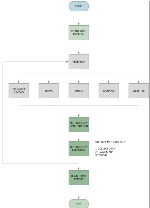
4 1.6 Overview
IDENTIFIYING PROBLEM
RESEARCH
BOOKS THESIS JOURNALS WEBSITES
LITERATURE REVEWS METHODOLOGY CONSTRUCTION METHODOLOGY EXECUTION DEMO / FINAL REPORT END START STEPS OF METHODOLOGY: 1. COLLECT DATA 2.TRAINING ANN 3.TESTING
CHAPTER 2
LITERATURE REVIEW
2.1 Chapter Overview
In this chapter is includes the important studies which have been done previously by other researchers. All their paper works and related research as well as the studies regard to this project is also included. Refer to the paper, much knowledge is applied and certain suggestions will be used to implement for this project.
Literature review was an ongoing process throughout the whole process of the project. It is very essential to refer to the variety of sources in order to gain more knowledge and skills to complete this project. These sources include reference books, thesis, journals and also the materials obtained from internet.
The basic concept of fault in induction motor has been well acquired. In addition, the function of all the components used in this project such as basic operation of MATLAB, Neural Network variations, and so on was explored first before starting the project.
6 2.2 Induction Motor
Induction motor is frequently used in industrial because it probably the simplest and most rugged of all electric motor. These motor also absence of brushes and ability to control speed of motor. Three phase is used because it is more
compact, simple design, high starting torque and less costly than single phase on the same voltage class and rating.
They consist of two basic parts which is the wound stator and the rotor
assembly. The outsider is stator which is having coil supplied with alternating current to produce a rotating magnetic. The insider is rotor was attached to output shaft that given a torque by rotating field. Rotor in secondary side is the part that converts electrical energy to mechanical energy. Most electric power distributed in form three-phase AC and rotate through the magnetic field they generate power which is sent out on three lines as three-phase power.
The theoretical analysis and modeling are necessary to distinguish relevant frequency components from others that may be present due to time harmonics, motor saturation [5]. Nonlinearity and saturation effects are being considered by the researchers for more accurate modeling and simulation of faulty motors [6], [7], [8], [9]. New condition monitoring techniques of stator inter-turn faults are being based on the frequency content of the transient line-to-line voltage after the motor is switched off and the transient voltage and currents during loading and unloading [10]. Condition monitoring aspects must be fully considered at design, development, and installation stages. The various key areas like failure mode, failure pattern, appearance, application, and maintenance history should be considered in order to accurately diagnose the cause of a winding failure [12]. Opportunities should be explored for using noise as a parameter extensively [13].
7 2.3 Artifical Intelligence
Artifical Intelligence (AI) is the intelligence of machines and part of the computer to create a system that perceives its environment and takes actions that full its chances of success. By using Artificial Intelligence through the science and engineering will produce or making intelligence machines.
The essence of an expert system is the ability to manage knowledge-based production rules that model the physical system, while it is a main feature of NNs that they are general non-linear function approximators. This function approximation is achieved by using an appropriate network built up from artificial neurons, which are connected by appropriate weights. However, the exact architecture of a NN is not known in advance; it is usually obtained after a trial-and-error procedure. Fuzzy logic systems are expert, rule-based systems, but they can also be considered to be general nonlinear function approximators. In contrast to NNs, they give a very clear physical description of how the function approximation is performed (since the rules show clearly the function approximation mechanism). On the other hand, fuzzy-NNs are basically NNs with fuzzy features, and it is one main advantage over “pure” NNs that their architecture is well defined [11]. Research trends show that AI techniques will have a greater role in electrical motor diagnostic system with advance practicability, sensitivity, reliability and automation. Diagnostic system based upon fuzzy neural will be very extensively used. Self- repairing electrical drives based upon genetic-algorithm-assisted neural and fuzzy neural systems will also be widely used in the near future [1], [2]. The explored opportunities are to add intelligence to motors, providing a level of communication and diagnostic capability [3], [4].
8 2.4 Parameters of motor monitoring
There are many various monitoring techniques for induction motors using different machine variables that been used by researchers. Fault will be detected through this parameters monitoring. These monitoring techniques have been classified into the following 13 categories using different parameters. It is listed as :
A) Magnetic Flux
Any distortion in the air-gap flux density due to stator defects will set up an axial homopolar flux in the shaft, which can be sensed by a search coil fitted around the shaft. The air-gap flux can also be sensed by sensing the voltage across two properly located motor coils. One can get a signal by subtracting these two voltages, which is independent of stator ir drop and approximately independent of motor leakage reactance drop. By using a minimum of four search coils located ax symmetrically to the drive shaft, the location of shorted turn can be found out [14].
B) Power
The instantaneous electric power has definite advantages in comparison to current as a detection parameter. The characteristic spectral component of the power appears directly at the frequency of the disturbance, independent of the synchronous speed of the motor. The utilization of the instantaneous power enhances the reliability of the diagnostics of the induction motors [15].
C) Temperature
A rugged temperature, the sensor can be mounted on the winding or embedded in the insulation, which is electrically isolated from its instrumentation [16]. The temperature estimation can be based on the thermal model and stator resistance model if unobstructed ventilation is ensured, and ambient temperature is accounted for plus the effect of elevation on the motor temperature and cooling [17], [18], [19]. The phenomenon of setting up of the space charge as a consequence of the aging of the stator insulation has been utilized for the thermal step method (TSM). The measurement of thermally stimulated discharge currents (TSDC) is also made which
9 gives the energy levels of the traps. By associating TSM and TSDC, a complete study of the apparition and of the development of the space charges can be made and the stator insulation lifetime can be predicted [20]. A nondestructive diagnostic apparatus using plastic-optical-fiber (POF) sensor has been developed for evaluating the aging of insulating resins for low-voltage induction motors. This apparatus measures the change of reflective absorbance ratio at two different near-IR wavelengths [21].
D) Gas Analysis
The degradation of the electrical insulation within a motor produces carbon monoxide gas which passes into the cooling air circuit and can be detected by an infrared (IR) absorption technique [16]. The high-frequency pulsewidth-modulation (PWM) pulses generate excessive voltage peaks leading to the start of motor insulation breakdown. It occurs as a result of electrostatic fields surrounding oppositely polarized conductors that begin to strip electrons from the surrounding air gap, leaving molecules with positive electrical charge (ionization) producing ozone which get combined with nitrogen from the air to produce forms of nitrous oxides. It corrosively attacks the insulation causing embitterment and eventual fracture. Ozone sniffing techniques are used for the detection of ozone [22], [23], [24].
E) Vibration
The stator frame vibration is a function of inter turn winding faults, single phasing, and supply-voltage unbalance. The resonance between the exciting electromagnetic (EM) force and the stator is one of the main causes of noise production in electrical machines [16], [25], [26], [27].
F) Induced Voltage
The voltage induced along the shaft of a machine (generator) is an indication of the stator core or winding degradation. Shaft voltage has not yet proved to be a useful parameter for continuous monitoring because it is difficult to measure in a reliable way. Moreover, it has also been shown that any damage to the core or the winding would need to be substantial before a significant variation in shaft voltage occurred [16]. The changes in the root mean square (rms) magnitude of Vsum(Vsum, rms ) can reveal the presence and severity of turn-fault diagnostics where Vsum is the sum
10 of instantaneous phase voltages. The maximum turn-fault sensitivity is obtained after bandpass filtering around the fundamental frequency [28].
G) Noise/Acoustic Noise
The noise spectrum of induction machines is dominated by EM, ventilation, and acoustic noise. Ventilation noise is associated with air turbulence, which is produced by periodic disturbances in the air pressure due to rotating parts. The EM noise is due to the action of Maxwell’s stresses that act on the iron surfaces in the presence of a magnetic field. These forces induce vibrations in the stator structure, which cause radiated noise. The sound power level due to aerodynamic and mechanical noise increases at a rate of 12 dB per doubling of the motor speed. Increased motor speed gives rise to EM noise [26]. The ground wall insulation interrogation can be done by optimally launching an ultrasonic wave into a stator bar and using the conductor as a waveguide [30].
H) Surge Testing
The surge testing is an established method for diagnosing winding faults. In the surge comparison test, two identical high voltages, high-frequency pulses are simultaneously imposed on two phases of the motor winding with third phase grounded. An oscilloscope is used to compare the reflected pulses indicating the insulation faults between windings, coils, and group of coils [41]. The pulse-pulse surge testing is a predictive field method to show the turn-turn insulation weakness before the turn-turn short occurs. An electronic and portable device “Surge Tester” is used to locate insulation faults and winding dissymmetry [31], [32], [33], [34].
I) Instantaneous Angular Speed
Various asymmetry faults in induction motors can be detected by monitoring the stator core vibration using instantaneous angular speed (IAS) techniques. In case of stator winding fault or unbalanced supply, the vibration signal will contain a significant component with twice the supply frequency. For phase imbalance, the fault symptom is a significant increase in the 100-Hz component (if the supply frequency is 50 Hz) [36].
11 J) Motor Circuit Analysis
By measuring the EM properties of the electric motor as an electric circuit, the motor circuit analysis (MCA) determines the variations within the motor and identifies the defects. In MCA, a low amount of energy with amplified responses is applied. The responses help in evaluating the condition of both the windings and rotor through the comparative readings [37], [38], [39].
L) Current
The current drawn by an ideal motor will have a single component at the supply. The motor current signature analysis (MCSA) utilizes the results of the spectral analysis of the stator current of an induction motor to pinpoint an existing or incipient failure of the motor or the driven system. The diagnostic analysis has been reported by various researchers using the sequence components of current, radio-frequency (RF) component of neutral current, and shaft currents [40].
M) Air-Gap Torque
The air-gap torque is produced by the flux linkage and the currents of a rotating machine. It is sensitive to any unbalance created due to defects as well as by the unbalanced voltages. The zero frequency of the air-gap harmonics shows that the motor is normal. In case of an induction motor with single-phase stator winding, the angular speed (as observed from the rotor) of forward and backward stator is rotating fields, the rotor and rotor rotating magnetic fields. The forward stator rotating field produces a constant torque while the backward stator field interacting with the rotor field produces a harmonic torque. This means the double fundamental frequency torque indicates the gap in the stator winding and/or voltage [41].
2.5 Faults in Induction Motor
Induction motors play an important role in manufacturing environments, therefore, this type of machine is mainly considered and many diagnostic procedures are proposed both from industry and from academia. [48]