M
ULTICELL
C
OOPERATION
I
NTRODUCTION
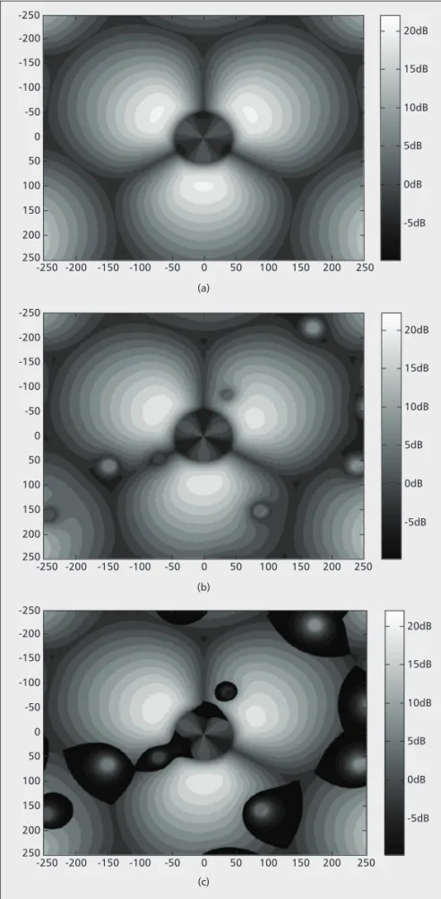
During the standardization process of Third Generation Partnership Project (3GPP) Long Term Evolution (LTE)-Advanced [1], a number of techniques have been proposed to boost the peak data rates, such as carrier aggregation and downlink multiple-input multiple-output (MIMO) up to eight layers. By taking advan-tages of these techniques, peak rates up to 100 Mb/s for high mobility and 1 Gb/s for low mobil-ity are envisaged. However, intercell interference is preventing ubiquitous user experience of such high data rate (i.e., the data rate achieved by cell edge users is a small fraction of the peak data rate). Nonuniform signal-to-interference-plus-noise ratio (SINR) distribution of a typical homogeneous network with 500 m inter-site dis-tance is depicted in Fig. 1a. Over 20 dB SINR is achieved in the cell center; however, it can only reach 5 dB or below in most areas due to inter-cell interference.
The heterogeneous network is an emerging network deployment. In a heterogeneous
net-work the layer of a planned homogeneous macro network is overlaid by layers of low-power nodes (LPNs), such as picocells and remote radio heads (RRHs). The macrocell provides wide-area coverage, and LPNs pro-vide coverage for hotspots and offload traffic from the macrocell. The gain of offloading traffic is limited due to imbalanced transmis-sion power (i.e., LPN coverage is shrunk by the high-power macrocell). To extend the LPN coverage, an offset to the received power mea-surement is introduced in cell selection, allow-ing more user equipment (UE) to be attached to the LPN. The problem of this approach is that it dramatically increases the interference the macrocell imposes on UE attached to the LPN by coverage expansion. Figures 1b and 1c show SINR distribution of a heterogeneous network deployment without and with coverage expansion, respectively. Two LPNs are placed randomly in the coverage of each macrocell. It can be seen that the expanded region suffers very low SINR, which is depicted by deep color in the figure.
F r o m i n f o r m a t i o n t h e o r y i t i s a l r e a d y known that intercell interference can be seen as an opportunity if cells process signals coop-eratively. Coordination techniques can be c l a s s i f i e d a s s e m i - s t a t i c c o o r d i n a t i o n a n d d y n a m i c c o o r d i n a t i o n a c c o r d i n g t o t h e requirement of information sharing across cells. Semi-static coordination techniques, including fractional frequency reuse (FFR) [ 2 ] , s o f t f r e q u e n c y r e u s e ( S F R ) [ 3 ] , a n d enhanced intercell interference coordination (eICIC) [4], require little time-insensitive information exchange across cells. The basic idea of FFR is to create partitions between cell edge and cell center UE based on SINR. Resources of cell center UE in every cell are reused, , thus removing adjacent cell interfer-e n c interfer-e t o c interfer-e l l interfer-e d g interfer-e U E . I n t h interfer-e c a s interfer-e o f S F R , edge UE devices are restricted to those allo-cated orthogonal resources by coordination of neighboring cells as in FFR. Higher per-cell
S
HAOHUIS
UN, P
EKINGU
NIVERSITY ANDS
TATEK
EYL
ABORATORY OFW
IRELESSM
OBILEC
OMMUNICATIONS(CATT)
Q
IUBING
AO, Y
INGP
ENG, Y
INGMINW
ANG, S
TATEK
EYL
ABORATORY OFW
IRELESSM
OBILEC
OMMUNICATIONS(CATT)
L
INGYANGS
ONG, P
EKINGU
NIVERSITYA
BSTRACT
Intercell interference management has become a critical issue for future cellular mobile systems. Coordinated multipoint transmission/ reception, or CoMP, is an effective way of man-aging intercell interference, and has been regard-ed as a key technology of LTE-Advancregard-ed. This article first provides an overview of downlink CoMP techniques specified in 3GPP LTE Rel-11, which mainly focuses on transmission schemes, channel state information reporting, interference measurement, and reference signal design. Then uplink CoMP is discussed in brief as most of the coordination gain can be achieved by implementation with little standardization support. Evaluation results are provided to show the efficiency of CoMP. The challenges as well as possible solutions for future CoMP standard-ization are also discussed.
I
NTERFERENCE
M
ANAGEMENT THROUGH
C
O
MP
IN
resource utilization is achieved by reusing all resources in every cell but with a lower trans-mit power given to center UE to trans-mitigate the increased interference. Both FFR and SFR are supported since LTE Release 8 (Rel-8).
In LTE Rel-10, the time-division multiplexing (TDM) eICIC principle was exploited to miti-gate interference from macrocell to picocells in heterogeneous network. The macrocell transmits an almost blank subframe (ABS) or multimedia broadcast over single-frequency network (MBSFN) subframe with a certain periodicity, but the picocells transmit normal subframes all the time. The macrocell is not allowed to sched-ule any UE in an ABS or MBSFN subframe. The UE connected to picocells in the expanded region can be scheduled during transmission of an ABS or MBSFN from the macrocell, while UE close to picocells may be scheduled in any subframe.
Semi-static coordination techniques devel-oped in LTE Rel-8/9/10 can provide benefits in managing intercell interference with relatively little backhaul overhead and low implementation complexity. However, the achievable benefit is limited as it is not able to follow the dynamic interference condition caused by dynamic scheduling and beamforming. Moreover, semi-statically preserved resources result in low effi-ciency of resource utilization.
Dynamically coordinating the transmission and reception of signals at multiple cells could lead to further performance improvement. Existing dynamic multi-cell coordinating schemes include network MIMO [5], distribut-ed MIMO [6], multicell MIMO [7], and so on. These schemes are conceptually the same, pro-viding promising improvements of spectral efficiency and more uniform throughput distri-bution. They are unified into coordinated mul-tipoint (CoMP) transmission/reception in 3GPP discussion as a key technology of LTE-Advanced. CoMP was initially brought forward in the study item of LTE-Advanced [1] to meet the requirements of IMT-Advanced [8] in 2008. However, there was no consensus on the gain of CoMP under realistic conditions, and it was not included in LTE Rel-10. Instead, a study item on CoMP was proposed to continue to study the performance benefits and specification impacts. After further study, performance gain was identified, and a work item was approved to specify CoMP in LTE Rel-11.
In the following sections, standardized CoMP in 3GPP LTE-Advanced is described. Downlink and uplink CoMP are introduced. Evaluation results are presented to show performance gains of CoMP. Conclusions are drawn, and future challenges are also discussed.
C
O
MP
IN
3GPP LTE-A
DVANCED
Both downlink and uplink CoMP are standard-ized to support four identified CoMP scenar-ios. Downlink CoMP involves channel state information (CSI) reporting from UE, interfer-ence measurement, and referinterfer-ence signal design, which require much standardization work. Uplink CoMP, on the other hand, can be implemented with little standardization sup-port. To optimize performance of uplink CoMP, uplink reference signal and uplink power control are enhanced in a CoMP-favor-able manner.Figure 1.SINR distribution: a) homogeneous macro network; b) heteroge-neous network without coverage expansion; c) heterogeheteroge-neous network with coverage expansion. (a) -200 -250 200 250 150 100 50 20dB 0 -50 -100 -150 -200 -250 15dB 10dB 5dB 0dB -5dB -150 -100 -50 0 50 100 150 200 250 (b) -200 -250 200 250 150 100 50 20dB 0 -50 -100 -150 -200 -250 15dB 10dB 5dB 0dB -5dB -150 -100 -50 0 50 100 150 200 250 (c) -200 -250 200 250 150 100 50 20dB 0 -50 -100 -150 -200 -250 15dB 10dB 5dB 0dB -5dB -150 -100 -50 0 50 100 150 200 250
S
CENARIOSFour scenarios were defined in the 3GPP LTE-Advanced CoMP study [9]. The defined scenar-ios are deployed in numerical evaluations, and standardization is aimed at providing support for all four scenarios. It is worth noting that 3GPP standardization focuses on scenarios that are with backhaul of low latency and sufficient capacity in LTE Rel-11. The four defined sce-narios are illustrated in Fig. 2.
Scenario 1:Homogeneous network with intra -site CoMP. The coordination takes place between three sectors of the same site in a homogeneous macro network. This is the most prevalent deployment scenario at the current stage, and CoMP can be applied in this scenario without any additional investment in network infrastructure.
Scenario 2:Homogeneous network with high-transmission-power RRHs. RRHs with equal transmission power to that of the eNodeB are employed to construct a homogeneous network. The coordination area consists of RRHs con-trolled by the same eNodeB. More CoMP gain could be achieved than with scenario 1 due to a possibly larger coordination area.
Scenario 3:Heterogeneous network with low-power RRHs within macrocell coverage. A num-ber of low-power RRHs connected to an eNodeB are deployed in macrocell coverage. Each RRH forms a small cell with physical cell identity (PCI) independent from the macrocell. As explained in the introduction, interference imposed by a macrocell on UE associated with RRH severely degrades system performance. The interference problem could be resolved by applying CoMP in this scenario.
Scenario 4:Heterogeneous network with low-power RRHs within macrocell coverage where the transmission/reception points created by the RRHs have the same PCI as the macrocell. The main difference from scenario 3 is that no new cell is formed by RRH in this scenario, which results in distinct control channel design and mobility management. However, from aspect of data transmission, there is no difference between the two scenarios since the network topology is the same.
In scenario 1, the coordinated cells are collo-cated, and it does not suffer from the restrictions of underlying backhaul. In scenarios 2–4 the RRHs are connected to the eNodeB via optical fiber, and it is assumed that information is exchanged without latency and capacity con-straints. For the sake of simplicity, a macrocell or an RRH is called a transmission point (TP) in downlink and receiving point (RP) in uplink.
D
OWNLINKC
OMP
For downlink CoMP techniques, specification efforts mainly focus on transmission schemes, CSI reporting, interference measurement, refer-ence signal design, and control signaling [9]. Transmission schemes are not mentioned explic-itly in the specification; however, all the specifi-cation items are to support CoMP transmission schemes. CSI reporting facilitates link adapta-tion in the network, while interference measure-ment and reference signal are essential in deriving a CSI report. Besides common stan-dardization support for frequency-division duplex (FDD) and time-division duplex (TDD) systems, special attention was paid to TDD to exploit channel reciprocity.
General Specification Support for FDD and TDD
Transmission Schemes— In the framework of 3GPP, downlink CoMP transmission is categorized as dynamic point selection (DPS), dynamic point blanking (DPB), joint transmission (JT), and coordinated scheduling/beamforming (CS/CB). The four categories of transmission schemes are shown in Fig. 3.
With DPS, a TP is dynamically selected according to the instantaneous channel condition on per-subframe basis. The TP with the best link quality is selected to exploit channel variations opportunistically (i.e., selection diversity gain is achieved). In general, the gain of selection diver-sity in addition to the already achieved frequen-cy and spatial diversity is marginal. To get further gain, DPB can be used in conjunction with DPS. By DPB, the dominant interferer(s) to UE in the coordination area is identified and muted dynamically (i.e., no signal is transmitted from the identified TP). By muting the dominant interferer, SINR of the UE may be enhanced Figure 2.CoMP scenarios in 3GPP LTE-Advanced.
Scenario 1 Scenario 3 Scenario 2 RRH eNodeB RRH eNodeB Different cells Scenario 4 RRH eNodeB RRH Same cell eNodeB RRH RRH
In the framework of
3GPP, downlink
CoMP transmission is
categorized as
dynamic point
selection (DPS),
dynamic point
blanking (DPB), joint
transmission (JT),
and coordinated
scheduling/beam-forming (CS/CB).
significantly as a few dominant interferers may contribute an absolute majority of the total interference. A TP is muted only when there is gain on the utility of the whole coordination area. Muting the dominant interferer causes per-formance loss of the particular TP. If perfor-mance improvements of those beneficiaries outweigh the loss, the TP can be muted; other-wise, it should remain active to transmit data. It seems unfair to UE connected to the muted TP; however, since scheduling is dynamically per-formed, those UE devices may also benefit from muting other TPs in subsequent subframes. On the whole, it is beneficial to all UE if the scheduling algorithm is designed carefully. DPS/DPB is especially useful in CoMP scenarios 3 and 4 as a muted macrocell benefits when mul-tiple RRHs reside in the macrocell. It is very likely that the boosted RRH performance could outweigh the loss of the macrocell.
JT represents the case where two or more TPs are transmitting signal to a single UE device on the same time-frequency resource. JT is categorized into coherent and non-coher-ent JT, depending on whether cohernon-coher-ent com-bining of signals from multiple TPs is targeted. Coherent JT offers the best performance among all considered CoMP schemes, since it allows multiple TPs to completely nullify inter-ference toward co-scheduled UE. As evidenced in [10], coherent JT is especially sensitive to imperfections of CSI, so it would be premature to include it in the standard considering the current state of the art. Therefore, there is no explicit support for coherent JT in LTE Rel-11; nevertheless, it can be implemented in TDD by channel reciprocity. Non-coherent JT is not able to nullify interference across multi-ple TPs due to the lack of relative phase infor-mation across TPs. The SINR at UE could be boosted by non-coherent JT, but with area-splitting-gain loss, as multiple TPs could instead schedule multiple separate UE devices. Only UE devices located on the coverage edge of two TPs are able to get benefit from non-coherent JT, for the area-splitting-gain loss could be compensated by the boosted through-put in low SINR regions. The gain of non-coherent JT is more prominent in a network with low traffic load, as vacant resources of neighboring TPs could be borrowed to perform non-coherent JT.
With CS/CB, the scheduling and beamform-ing across different TPs are aligned to reduce interference. Coordinating scheduling decisions (i.e., which specific UE is selected for transmis-sion) can help alleviate strong interference con-ditions. In addition, a wise selection of beamforming weights may further contribute to reduce interference. Ideally, scheduling and beam selection should be carried out jointly to optimize performance. However, it is impractical to make joint decisions on UE and beams across multiple TPs. A simple and prevalent way to implement CS/CB is an iterative scheduling pro-cedure. Each cell revisits the choice of UE and underlying transmit beam(s) based on scheduling decisions and beams decided by other cells in the previous iteration. An updated scheduling decision not only accounts for the utility of the scheduled UE but also for the utility of the vic-tim UE that has been tentatively scheduled by other cells in the previous iteration. The goal of each updating is to maximize a global utility (e.g., the total weighted throughput with the coordination area). Only a few numbers of itera-tions are needed to reach a near-optimal solu-tion.
In practice, there is no clear boundary between transmission schemes; that is, combina-tion of transmission schemes is possible. For example, an RRH is selected for data transmis-sion for UE, and the scheduling and beams deci-sions are coordinated across multiple RRHs while the macrocell is muted. In LTE Rel-11, all of the above transmission schemes can be sup-ported in a transparent manner from the specifi-cation perspective.
CSI Reporting— Channel state information at the transmitter is necessary to take advantage of multiple antenna techniques. LTE Rel-8 employs implicit feedback; that is, the reported CSI is a set of transmission parameters recommended by UE corresponding to a transmission hypothesis. The parameters are derived under the transmis-sion hypothesis. CSI includes the precoding matrix indicator (PMI), rank indicator (RI), and channel quality indicator (CQI). The RI is the transmission rank or number of independent data streams that can be supported by the chan-nel in spatial multiplexing transmission. The PMI is an index to a codeword in a predefined codebook comprising precoding matrices. The Figure 3.Illustration of CoMP transmission schemes: a) dynamic point selection; b) dynamic point
blank-ing; c) joint transmission; d) CS/CB.
TP1 TP2 Dynamic selection (a) TP1 TP2 Coherent/non-coherent combining (c) TP1 TP2 TP1 TP2 Dynamic blanking (b) (d)
With CS/CB,
the scheduling and
beamforming across
different TPs are
aligned to reduce
interference.
Coordinating
scheduling decisions
(i.e., which specific
UE is selected for
transmission)
can help alleviate
strong interference
conditions.
indexed codeword can be used as transmit beam-forming weight for UE directly or used in deriv-ing transmit beamformderiv-ing weight. The CQI reflects the quality of the target link, which is a reference for modulation and coding scheme (MCS) selection.
A transmission hypothesis in CoMP compris-es two parts: signal hypothcompris-esis and interference hypothesis. The signal hypothesis specifies TP(s) from which the packet data is assumed to be transmitted, and the interference hypothesis stands for interference suffered during the assumed data transmission. For DPS, CSI of transmission hypotheses with signal hypothesis from each candidate TP is needed at the net-work to facilitate dynamic selection of TPs. In addition, for DPB, CSI of transmission hypothe-ses with the same signal hypothesis but different interference hypotheses (e.g., whether an inter-fering TP is muted or not) are necessary for the network to make a decision on whether or not to mute the interfering TP.
To maximize flexibility in scheduling in the network, CSI of all possible transmission hypotheses should be reported by UE. However, the feedback overhead and UE implementation complexity is proportional to the number of hypotheses. To limit feedback overhead while retaining flexibility, Rel-11 UE can be config-ured to report CSI corresponding to one or more transmission hypotheses. CSI correspond-ing to one transmission hypothesis is defined as a CSI process. A CSI process is determined by the association of a signal hypothesis and an interference hypothesis, where the signal hypoth-esis and interference hypothhypoth-esis are measured through CSI-RS and interference measurement resource (IMR), respectively. Note that there is no transmission hypothesis corresponding to JT and CS/CB in Rel-11 feedback, since that CSI can be calculated from the CSI of the DPS/DPB transmission hypothesis in the network without significant performance loss.
Assuming there are two TPs involved in CSI reporting, the possible CSI processes are illus-trated in Table 1. In each transmission hypoth-esis, the signal can be transmitted from either TP1 (TP1 on, TP2 off) or TP2 (TP2 on, TP1 off), and the interference from the interfering TP can be either muted (off) or not (on). There are four possible CSI processes in the consid-ered example. For CSI1in Table 1, the signal
from TP1 is “on” and the signal from TP2 is “off,” which means that the signal is transmit-ted from TP1 only. Regarding the interference hypothesis, the interference from TP1 is “off” and that from TP2 is “on,” which means that the assumed transmission experiences interfer-ence from TP2. The corresponding transmission hypothesis is DPS from TP1. Unlike CSI1,
inter-ference from TP2 is “off” for CSI2, and thus
CSI2can be used directly for DPB transmission
from TP1 while muting TP2. CSI with JT and CS/CB transmission hypotheses are not sup-ported in LTE Rel-11, and the required CSI could be inferred from CSI2and CSI4. It is
worth noting that by the association of signal hypothesis and interference hypothesis, CSI processes besides the listed ones could also be configured.
Interference Measurement— To derive the CSI of each CSI process, appropriate interference cor-responding to the interference hypothesis should be measured by UE. In addition, accuracy is another requirement since CoMP performance is sensitive to accuracy of interference measure-ment. To facilitate CSI reporting, LTE Rel-11 introduces a UE-specific interference measure-ment resource (IMR) for UE to measure inter-ference. Each CSI process is linked with a configured IMR, and the interference hypothesis of the CSI process is derived on the IMR.
Each IMR occupies a subset of resource ele-ments (REs) that are muted intentionally on cer-tain TPs. No signal is transmitted from those TPs on IMR occupied REs. UE simply receives the signal on those REs to get interference esti-mation. The network should coordinate the sig-nal transmission on configured IMR for TPs in the coordination area to ensure that the signal on the IMR matches the interference hypothesis. To elaborate more clearly, Fig. 4 depicts several IMR configurations. On IMR1, both TP1 and TP2 are muted; the received signal on those REs represents interference from TPs other than TP1 and TP2. Similarly, UE could estimate interfer-ence out of {TP1} and {TP2} on IMR2 and IMR3, respectively.
Reference Signal Design— The design philosophy of LTE-Advanced reference signal (RS) is to separate RS for CSI reporting (CSI-RS) and RS for demodulation (DM-RS). For CSI reporting, RS sparse in time and frequency domain is sufficient. The sparsity significantly reduces system overhead. For demodulation, higher RS density is necessary to meet demodu-lation requirements. DM-RS only needs to be transmitted in the resources scheduled for data transmission. It is transmitted in the same way as data, and thus the transmitted data can be demodulated by referring to DM-RS without knowing the actual CoMP transmission scheme. This gives the network sufficient flexibility in choosing a CoMP transmission scheme to opti-mize performance.
A CSI-RS-resource refers to some predefined time/frequency/code resources used for transmis-sion of CSI-RS from a certain TP. To support CoMP transmission, multiple CSI-RS-resources need to be configured for UE. The configured set of CSI-RS-resources is defined as a CoMP
Table 1.Example CSI process configuration for two TPs.
CSI process
Transmission hypothesis
Signal hypothesis Interference hypothesis
TP1 TP2 TP1 TP2
CSI1 on off off on
CSI2 on off off off
CSI3 off on on off
measurement set. Each CSI-RS-resource in a CoMP measurement set is used to track the channel of one TP. A CSI process is associated with a CSI-RS-resource in the CoMP measure-ment set to derive the signal hypothesis of the CSI process.
Special Considerations for TDD— In a TDD system, channel reciprocity can be exploited to reduce feedback overhead and improve CSI reporting accuracy. CSI obtained by channel reciprocity is free of quantization and feedback compression errors, and thus more accurate than that report-ed by UE. CQI reporting from UE is still nereport-ed- need-ed to deliver information about downlink interference, which is different from interference measured on an uplink channel. In principle, reported CQI along with CSI by channel reciprocity enables all kinds of transmission schemes. Even with CQI reporting, the feedback overhead is still greatly reduced by the absence of PMI/RI reporting.
Although coherent JT is not supported explic-itly in Rel-11, it can be implemented in a TDD system to achieve significant performance gain. A prerequisite of coherent JT is that channel reciprocity holds over multiple TPs. Antenna calibration across multiple TPs should be carried out to ensure overall channel reciprocity.
Channel-reciprocity-based schemes rely heav-ily on the accurate reception of an uplink sound-ing reference signal (SRS). Coordination of SRS transmission among multiple TPs is beneficial in improving channel estimation accuracy. By such coordination, the SRS transmission in one cell
(TP) is orthogonal to other cells in the coordina-tion area, reducing interference imposed on SRS transmission.
The targets of SRS transmission may be locat-ed at separate positions, and the distances from UE to those targets are different. The transmis-sion power should be set to guarantee that the furthest TP can receive the SRS correctly. Enhanced transmission power is also beneficial to uplink CoMP in deriving uplink CSI at multi-ple RPs.
U
PLINKC
OMP
For uplink CoMP, uplink CSI is available in the network without resource-consuming transmis-sion on uplink for CSI reporting. Terminals need almost no modification to support uplink CoMP transmission. It is easier to implement CoMP in uplink than in downlink from the UE perspec-tive. Cooperation schemes are implementation-specific in the network, except that possible backhaul transmission needs to be standardized in future. To optimize uplink CoMP, uplink ref-erence signal and uplink power control are enhanced in a CoMP-favorable manner.
Uplink CoMP includes joint reception (JR) of the received signal at multiple RPs and/or coordinated scheduling (CS) decisions among RPs to control interference and improve cover-age.
Joint reception (JR):The basic concept behind JR is to utilize antennas at different sites. The signals received by the RPs are jointly pro-cessed to produce the final output. Received data needs to be transferred between the RPs Figure 4.Interference measurement resource (IMR) configuration examples.
IMR1 IMR2 IMR3
PDSCH transmission l = 6 l = 0 l = 0 l = 6 l= 6 l= 0 l = 0 l= 6
Even-numbered slots Odd-numbered slots
A. TP1
Even-numbered slots Odd-numbered slots
B. TP2 Muted for interference measurement
for them to operate. The amount of exchanged information between cooperating RPs depends on to what extent the received signals are pre-processed before information exchange. Quan-tized baseband samples convey the most complete information for joint processing. It achieves the best performance, while the load on backhaul is also the highest. Further processing at RPs can lower the load of backhaul, but with less CoMP gain. There is clearly a trade-off between CoMP gain and backhaul overhead.
Coordinated scheduling (CS):UE scheduling and precoding selection decisions are aligned among RPs in a coordination area to minimize interference. A much reduced load is achieved in the backhaul network because only CSI and resource allocation information needs to be shared among cooperating RPs.
In a heterogeneous network, the transmis-sion power of various nodes may differ dramati-cally. For example, transmission power of a macro node may be 10~20 dB higher than that of a lower-power RRH. As a result, the cell boundary between a macro node and an RRH node (similar received signal level between nodes) is actually very close to the RRH node. It is very likely that cell edge UE connected to a macro node is closer to an RRH. In this case, the RRH received signal strength of the UE uplink transmission is stronger than that of the macro node. That is, the uplink transmission of such UE can target the RRH instead of the macro node. The transmission power can thus be lowered to reduce interference and extend battery life. The transmission of uplink and downlink are decoupled in this scenario. Note that this can be viewed as a special type of joint reception.
It is worth noting that uplink CoMP coopera-tion schemes are not limited to those mencoopera-tioned in this article. Network is free to choose any schemes that benefit uplink transmission.
E
VALUATIONS
Extensive evaluation work has been carried out during the study phase of CoMP in 3GPP [9]. By the collected results in [9], performance benefits of both downlink and uplink CoMP are identi-fied. In this section, evaluation results are given to verify the performance of downlink CoMP according to the latest progress in 3GPP. The simulation is implemented via Microsoft Visual C++ 2008.
E
VALUATIONR
ESULTS FORS
CENARIOS1
AND2
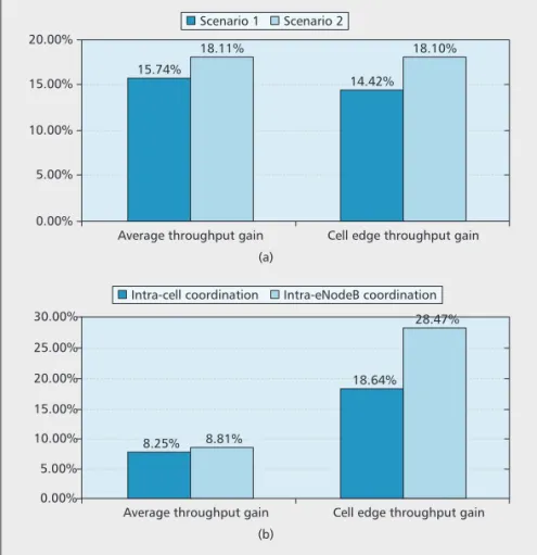
Coherent JT is evaluated in scenarios 1 and 2. CSI is obtained by channel reciprocity in the network. CQI for each cell is reported by UE. Each cell first performs single cell scheduling to select at most two UE devices without consider-ing intercell coordination. The transmit beam-forming of each selected UE is then jointly calculated to suppress interference to co-sched-uled UE in the coordination area. Figure 5a shows that coherent JT provides gain for cell center UE as well as cell edge UE because spa-tial reuse is allowed by multiple-user transmis-sion. If scheduling decisions are made jointly over the coordination area, further gain could be
expected. Other detailed evaluation assumptions can be found in [9].
E
VALUATIONR
ESULTS FORS
CENARIOS3
AND4
The combined scheme of DPS/DPB and non-coherent JT is evaluated in scenarios 3 and 4. TPs within a CoMP coordination area are joint-ly scheduled, and each CoMP coordination area is scheduled independently. Within each coordination area, exhaustive search is utilized to schedule the UE group and the correspond-ing transmission schemes (DPS, DPB, and non-coherent JT) that achieve the highest total weighted estimated throughput. UE reports all of the four CSI processes (CSI1–CSI4) to the
network as shown in Table 1. For DPS and DPB, the reported CSI is used directly, while for non-coherent JT, the network figures out required CSI from reported CSI. Both intra-sector and intra-eNodeB cooperation are eval-uated. The coordination area includes one macrocell and four RRHs within the macrocell (sector) in sector cooperation. For intra-eNodeB cooperation, coordination is carried out between three collocated macrocells (sec-tors) and 12 RRHs connected to those macro-cells (sectors). From a data transmission perspective, scenarios 3 and 4 are identical; thus, only one set of results is given. As seen in Fig. 5b, DPS/DPB and non-coherent JT pro-vide throughput gain mainly for UE with medi-an to low rates. Furthermore, the larger coordination area provides additional gain. Other detailed evaluation assumptions are aligned with [9].
Figure 5.Evaluation results of CoMP schemes: a) scenarios 1 and 2; b) sce-narios 3 and 4.
(a) Average throughput gain
15.74%
18.11%
Cell edge throughput gain 18.10% 5.00% 0.00% Scenario 1 Scenario 2 10.00% 15.00% 20.00% (b)
Average throughput gain Cell edge throughput gain 28.47%
5.00% 0.00%
Intra-cell coordination Intra-eNodeB coordination
15.00% 10.00% 20.00% 25.00% 30.00% 14.42% 8.25% 8.81% 18.64%
C
ONCLUSIONS AND
F
UTURE
W
ORK
This article has presented an overview of the standardization work on CoMP in 3GPP LTE-Advanced. Due to the limited timeframe of LTE Rel-11 standardization, only basic functions of CoMP are supported. The CoMP technique is far from mature, and many problems remain to be solved.1) Backhaul-efficient CoMP. Standardized CoMP in 3GPP assumes that an ideal backhaul connection exists. However, the available back-haul types are diverse in practice, such as T1/E1 and microwave. On these practical backhaul types, assumption of infinite capacity and zero latency are no longer valid. Smart and backhaul-efficient cooperation techniques are needed.
2) Efficient CSI feedback. CoMP perfor-mance gain, especially coherent JT, relies heavily on the accuracy of CSI in the network. In practi-cal systems, the accuracy of CSI in the network is limited by the capacity of uplink transmission. How to design efficient feedback over the limit-ed uplink to support aggressive CoMP schemes such as coherent JT poses big challenges on research and standardization.
3) Multiple-site antenna calibration for TDD. As seen from evaluation results, coherent JT exploiting channel reciprocity provides signifi-cant gain for TDD. However, channel reciprocity does not hold strictly. To ensure channel reciprocity and hence maximize the capability of coherent JT in TDD, antennas across multiple TPs need to be jointly calibrated. Self-calibration is difficult to implement, especially for scenarios 2–4. Over-the-air (OTA) calibration seems nec-essary in these scenarios. With the constraint of feedback overhead, the content of information reported by UE to network and the calibration algorithm need further study.
A
CKNOWLEDGMENTThe authors acknowledge the support from the National Science and Technology Major Project of China under Grant 2011ZX03003-001-01 and the National Basic Research Program of China under Grant 2012CB724103.
R
EFERENCES[1] 3GPP TR 36.814 v9.0.0, “Evolved Universal Terrestrial Radio Access (E-UTRA) and Evolved Universal Terrestrial Radio Access Network (E-UTRAN); Further Advance-ments for E-UTRA Physical Layer Aspects (Release 9),” TSG RAN.
[2] G. Boudreau et al., “Interference Coordination and
Can-cellation for 4G Networks,” IEEE Commun. Mag., vol.
47, no. 4, Apr. 2009, pp. 74–81.
[3] J. Li, N. Shroff, and E. Chong, “A Reduced-Power Chan-nel Reuse Scheme for Wireless Packet Cellular
Net-works,” IEEE/ACM Trans. Net., vol. 7, no. 6, Dec. 1999,
pp. 818–32.
[4] 3GPP R2-106897, “Introduction of Enhanced ICIC,” 3GPP TSG RAN WG2 meeting #72.
[5] H. Huang et al., “Increasing Downlink Cellular Throughput
with Limited Network MIMO Coordination,” IEEE Trans.
Wireless Commun., vol. 8, no. 6, June 2009, pp. 2983–89.
[6] A. Saleh, A. Rustako, and R. Roman, “Distributed Antennas
for Indoor Radio Communication,” IEEE Trans. Commun.,
vol. 35, no. 12, Dec. 1987, pp. 1245–51.
[7] D. Gesbert et al., “Multi-Cell MIMO Cooperative
Net-works: A New Look at Interference,” IEEE JSAC, vol. 28,
no. 9, Dec. 2010, pp. 1380–408.
[8] ITU-R Rep. M.2134, “Requirements Related to Technical Per-formance for IMT-Advanced Radio Interface(s),” 2008. [9] 3GPP TR 36.819 v11.1.0, “Evolved Universal Terrestrial
Radio Access (E-UTRA) and Evolved Universal Terrestrial Radio Access Network (E-UTRAN); Coordinated Multi-Point Operation for LTE Physical Layer Aspects (Release 11),” TSG RAN.
[10] S. Annapureddy et al., “Coordinated Joint
Transmis-sion in WWAN,” IEEE Commun. Theory Wksp., May
2010.
B
IOGRAPHIESSHAOHUISUN([email protected]) received a B.S. in auto control engineering and an M.S. in computer engineering from Xidian University in 1994 and 1999, respectively, and a Ph.D. in communication and information systems from Xidian University in 2003. He has been deeply involved in the development and standardization of LTE/LTE-Advanced since 2005. His research area of interest includes multiple-antenna technology, heterogeneous wireless networks, and relay.
QIUBINGAO([email protected]) received his B.S. and Ph.D. in control science and engineering from Tsinghua University, China. He is currently a senior research engi-neer at the Datang Wireless Mobile Innovation Center of the China Academy of Telecommunication Technolo-gy (CATT). His current research interests include physi-c a l l a y e r d e s i g n f o r m o b i l e physi-c o m m u n i physi-c a t i o n , multiple-antenna technology, CoMP, and system perfor-mance evaluation. He is inventor/co-inventor of more t h a n 1 0 0 p a t e n t s i n w i r e l e s s c o m m u n i c a t i o n s , a n d author/coauthor of a number of journal and conference papers.
YINGPENG([email protected]) received her M.Sc. and Ph.D.
in electrical and electronic engineering from the University of Bristol, United Kingdom. She is presently a senior stan-dardization researcher in the Wireless Mobile Innovation Center of CATT. Her research interests include 3GPP/ITU standardization, LTE/LTE-A physical layer design, CoMP, heterogeneous networks, and cognitive radio. She received First Prize in “4G TD-LTE-Advanced” of the Science and Technology Prize from CCSA in 2011.
YINGMINWANG[M] ([email protected]) received his Ph.D. degree in signal and information systems from Xidian University, Xi’an, China. He joined R&D of TD-SCDMA sys-tems at the Datang Mobile Communications Equipment Co., Ltd., Beijing, China, in 2000. He has served as chief scientist since 2010 in the Datang Telecom Technology and Industry Group. He is currently leading the Datang Wireless Mobile Innovation Center. His current research interests include digital communication signal processing and wire-less networks. He has applied for more than 150 patents in wireless communications and published a number of papers.
LI N G Y A N G SO N G [ S M ] ( l i n g y a n g . s o n g @ p k u . e d u . c n ) received his Ph.D. from the University of York, United Kingdom, in 2007, where he received the K. M. Stott Prize for excellent research. He worked as a postdoctor-al research fellow at the University of Oslo, Norway, and Harvard University, Cambridge, Massachusetts, until rejoining Philips Research UK in March 2008. In May 2009, he joined the School of Electronics Engineer-ing and Computer Science, PekEngineer-ing University, China, as a full professor. He is a co-inventor of a number of patents (standards contributions), and author or co-author of over 100 journal and conference papers. He has received best paper awards at three international conferences.