IMPLEMENTATION AND COMPARISON OF ISCSI
OVER RDMA
BY
ETHAN BURNS
B.S., University of New Hampshire (2006)
THESIS
Submitted to the University of New Hampshire in Partial Fulfillment of
the Requirements for the Degree of
Master of Science in
Computer Science
This thesis has been examined and approved.
Thesis director, Robert Russell,
Associate Professor of Computer Science
Radim Bartoˇs,
Associate Professor of Computer Science
Robert Noseworthy, UNH-IOL, Chief Engineer
Barry Reinhold,
President, Lamprey Networks
ACKNOWLEDGMENTS
I would like to thank Dr. Robert D. Russell for all of his help throughout this entire project. I would also like to thank my committee for their guidance and advice, and Mikkel Hagen for his critiques and suggestions. Finally, I would like to thank the iSCSI, OFA and iWARP groups at the University of New Hampshire InterOperability Lab for their vast knowledge and technical help.
TABLE OF CONTENTS
ACKNOWLEDGMENTS . . . iii
LIST OF TABLES . . . vii
LIST OF FIGURES . . . ix
ABSTRACT . . . x
1 INTRODUCTION 1 1.1 The iSCSI Protocol . . . 1
1.2 Remote Direct Memory Access . . . 2
1.3 iSCSI Extensions for RDMA . . . 4
1.4 Thesis Goals . . . 5 1.5 Outline . . . 5 2 BACKGROUND 8 2.1 SCSI . . . 8 2.2 iSCSI . . . 10 2.2.1 Login Phase . . . 12
2.2.2 Full Feature Phase . . . 14
2.2.3 Logout Phase . . . 17
2.3 RDMA . . . 18
2.3.1 Marker PDU Aligned Framing . . . 19
2.3.2 Direct Data Placement . . . 20
2.3.3 Remote Direct Memory Access Protocol . . . 23
2.4 iSER . . . 25
2.4.2 iSER Specific iSCSI Login/Text Keys . . . 28
2.4.3 iSER Inbound/Outbound RDMA Read Queue Depths . . . 28
2.4.4 iSER Connection Setup . . . 29
2.4.5 iSER Hello Message Exchange . . . 30
2.4.6 iSER Connection Termination . . . 30
2.4.7 iSER-Assisted iSCSI Read Operation . . . 30
2.4.8 iSER-Assisted iSCSI Write Operation . . . 32
2.4.9 iSER and Current RDMA Hardware . . . 33
3 IMPLEMENTATION 34 3.0.10 Protocol Layers . . . 34
3.1 iSCSI . . . 35
3.1.1 Three Steps . . . 36
3.1.2 Emulating the Kernel-Space APIs . . . 36
3.1.3 Moving to User-Space . . . 38
3.2 RDMA Interfaces . . . 40
3.3 Software iWARP . . . 41
3.3.1 Difficulties With the OFA Stack in User-Space . . . 44
3.4 Adding iSER Support . . . 45
3.4.1 iSER Modifications . . . 46
3.5 Moving to Kernel-Space . . . 47
3.5.1 Deferred Event Handling . . . 48
3.5.2 Call-back Functions v.s. Queues . . . 49
3.5.3 Memory Registration . . . 51
3.6 iSER Difficulties . . . 56
3.6.1 TCP Stream Transitioning . . . 56
3.6.2 Zero-based Virtual Addressing . . . 60
3.7 The Completed Implementation . . . 65
3.7.1 iSER Layer Layout . . . 65
3.7.2 iSCSI Target . . . 67
3.7.3 iSCSI Initiator . . . 70
4 RESULTS 74 4.1 Tests Performed . . . 74
4.2 Throughput . . . 76
4.2.1 Maximum Data Throughput . . . 77
4.2.2 Kernel-Space Throughput . . . 79
4.2.3 User-Space Throughput . . . 83
4.2.4 User-Space and Kernel-Space . . . 85
5 CONCLUSIONS 93 5.1 Conclusions . . . 93
5.2 Future Work . . . 94
LIST OF TABLES
4.1 Performance Test Combinations . . . 75
4.2 Header Bytes With iWARP RDMA . . . 78
4.3 Header Bytes With With TCP/IP . . . 78
LIST OF FIGURES
1-1 Traditional TCP Receiving Data . . . 3
1-2 RDMA Receiving Data . . . 3
1-3 Traditional TCP Sending Data . . . 4
1-4 RDMA Sending Data . . . 5
1-5 iSCSI-iSER-RDMA stack . . . 6
2-1 The iSER-Protocol Stack (with iWARP) . . . 9
2-2 Devices Connected Using Parallel SCSI . . . 10
2-3 Devices Connected Using iSCSI . . . 12
2-4 A Simple iSCSI Login . . . 15
2-5 An iSCSI Encapsulated SCSI READ Command . . . 16
2-6 An iSCSI Encapsulated SCSI WRITE Command . . . 17
2-7 A Theoretical DDP Frame Without MPA . . . 21
2-8 A DDP Segment Using MPA . . . 22
2-9 An iSER-Assisted iSCSI Read . . . 31
2-10 An iSER-Assisted iSCSI Write . . . 32
3-1 iSCSI-iSER-RDMA Stacks. . . 35
3-2 User-space iSCSI Implementation . . . 40
3-3 iSER Over OSC RNIC . . . 42
3-4 Hybrid Software/Hardware RDMA . . . 44
3-5 Pseudo Algorithm for Processing CQ Events . . . 46
3-6 Registered Memory Regions . . . 52
3-8 TCP Stream Transitioning, Theoretical V.S Actual . . . 58
3-9 Zero-based Virtual Addressing . . . 61
3-10 Non-Zero-Based Virtual Addressing . . . 62
3-11 iSER Headers . . . 64
3-12 iSER Target-Side Connection Establishment . . . 66
3-13 iSER Initiator-Side Connection Establishment . . . 67
3-14 iSCSI Target Thread Interactions . . . 70
3-15 iSCSI/iSER Layer Interaction . . . 71
3-16 iSCSI Initiator Thread Interactions . . . 72
4-1 Kernel-space iSCSI Read Throughput . . . 80
4-2 Kernel-space iSCSI Write Throughput . . . 82
4-3 Kernel-space iSER Read and Write Throughputs . . . 83
4-4 User-space iSCSI Read Throughput . . . 84
4-5 User-space iSCSI Write Throughput . . . 85
4-6 User-space iSER Read and Write Throughputs . . . 86
4-7 iSER Read Operation Throughput . . . 86
4-8 iSER Write Operation Throughput . . . 87
4-9 Hybrid User/Kernel-Space iSER Write Operation Throughput . . . 87
4-10 Kernel-space and User-space iSER-Assisted Initiator Layering . . . 88
4-11 Kernel-space and User-space 1MB Write Operation . . . 90
4-12 Hybrid User/Kernel-Space iSER Write Operation Throughput . . . 91
ABSTRACT
IMPLEMENTATION AND COMPARISON OF ISCSI OVER RDMA
by
ETHAN BURNS
University of New Hampshire, May, 2008
iSCSI is an emerging storage network technology that allows for block-level access to disk drives over a computer network. Since iSCSI runs over the very ubiquitous TCP/IP protocol it has many advantages over its more proprietary alternatives. Due to the recent movement toward 10 gigabit Ethernet, storage vendors are interested to see how this large increase in network bandwidth could benefit the iSCSI protocol.
In order to make full use of the bandwidth provided by a 10 gigabit Ethernet link, specialized Remote Direct Memory Access hardware is being developed to offload processing and reduce the data-copy-overhead found in a standard TCP/IP network stack. This thesis focuses on the development of an iSCSI implementation that is capable of supporting this new hardware and the evaluation of its performance.
This thesis depicts the approach used to implement the iSCSI Extensions for Remote Di-rect Memory Access (iSER) with the UNH iSCSI reference implementation. This approach involves a three step process: moving UNH-iSCSI from the Linux kernel to the Linux user-space, adding support for the iSER extensions to our user-space iSCSI and finally moving everything back into the Linux kernel. In addition to a description of the implementation, results are given that demonstrate the performance of the completed iSER-assisted iSCSI implementation.
CHAPTER 1
INTRODUCTION
1.1
The iSCSI Protocol
TheInternet Small Computer Systems Interface(iSCSI) [12] protocol is an emergingStorage Area Network (SAN) technology that uses the Internet Protocol (IP, specifically TCP/IP) as its underlying fabric. Since iSCSI uses the ubiquitous TCP/IP protocol instead of a specialized network fabric it has a lower total cost of ownership than other SAN technologies [7]. In addition to being less expensive than its competitors, iSCSI also has the ability to provide networked storage to home users over Local Area Networks (LANs) or across the wide area Internet [16] without requiring any specialized hardware.
The iSCSI protocol has yet to be adopted for wide-spread deployment. Part of the reason for this is because of the huge investment that most companies already have inFibre Channel (FC), the current leading SAN technology. Another reason that iSCSI has yet to see wide-spread deployment is that the IP networks that it uses don’t currently match the speed of other specialized fabrics. IP networks typically run at either 100 megabits per second (Mbits/s) or one gigabit per second (Gbit/sec) speeds, where as FC fabrics can run at about 4-8 Gbits/s, and Infiniband [2] (another competing technology) can reach speeds in the 40 Gbits/s range.
1.2
Remote Direct Memory Access
The current 10 Gbit/s Ethernet (10GigE) standard allows IP networks to reach competi-tive speeds, however, standard TCP/IP is not sufficient to make use of the entire 10GigE bandwidth. The reason that TCP/IP has a difficult time filling a 10GigE link on its own is because of data copying, packet processing and interrupt handling done on the CPU. In a traditional TCP/IP network stack an interrupt occurs for every packet being received, data is copied at least once in the host computer’s memory and the CPU is responsible for processing packet headers for all incoming and outgoing packets. In order to get rid of these inefficiencies, specialized Remote Direct Memory Access (RDMA) hardware is re-quired. RDMA hardware uses theiWARP protocol suite [4] [13] [11] to move data directly from the memory of one computer to the memory of a remote computer without extra copies at either end. RDMA hardware will reduce the number of data copies that are required by the TCP/IP network to one-per-host (between the memory and the wire) and it will offload a bulk of the network-processing from the CPU. This means that applications with RDMA support will have lower CPU usage and the ability to utilize a full 10GigE link.
Figures 1-1 and 1-2 give a depiction of the difference between traditional TCP and iWARP on the receiver end. Notice that, in Figure 1-1, the traditional TCP example, the CPU is interrupted for each TCP packet that it receives, it then needs to process the TCP packet and put the data at the correct position in the reassembly buffer. After the data is assembled the CPU copies it into the application’s receive buffer. With RDMA (Figure 1-2), the CPU is not involved; the RNIC assembles the TCP data straight into the application’s final receive buffer, no extra copying is required. This frees up the CPU to perform other tasks while removing the overhead involved in copying, interrupt handling and processing of TCP packets.
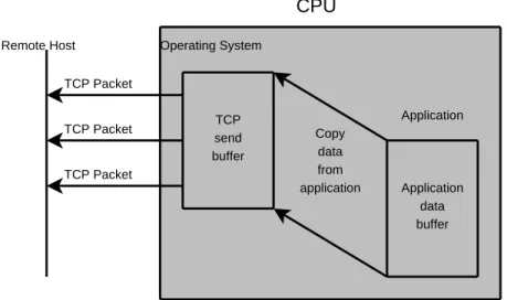
Figures 1-3 and 1-4 give a depiction of the difference between traditional TCP and iWARP on the sender side. In Figure 1-3 the application copies data into the operating system’s outgoing TCP buffer. The data must remain available in the operating system
Operating System TCP Packet TCP Packet TCP Packet TCP reassembly buffer Application Copy data to application Application receive buffer Remote Host CPU
Figure 1-1: Traditional TCP Receiving Data
Remote Host
RNIC
TCP-MPA-DDP-RDMAP Packet TCP-MPA-DDP-RDMAP Packet TCP-MPA-DDP-RDMAP Packet Application receive bufferOperating System TCP Packet TCP Packet TCP Packet TCP send buffer Application Copy data from application Application data buffer Remote Host CPU
Figure 1-3: Traditional TCP Sending Data
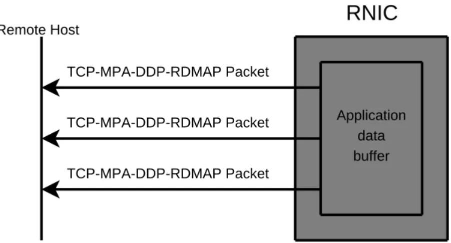
because data loss may require TCP retransmissions. Since retransmissions are hidden from the application, the operating system must retain its own copy of the data in case the application destroys the data buffer before all of the data is acknowledged by the receiver. The semantics of RDMA prevent the application from destroying the buffer before all of the data has been transmitted. In Figure 1-4 the RNIC is able to send data directly from the application’s buffer without the need of an extra copy.
1.3
iSCSI Extensions for RDMA
One of the difficulties with RDMA is that its usage differs from traditional TCP/IP and applications may need some re-designing to support it. In the case of iSCSI, a new IETF standard has been created that defines theiSCSI Extensions for RDMA (iSER) [8]. iSER describes a set of operational primitives that must be provided by an iSER implementation for use by an iSCSI implementation, and a description of how a conformant iSER-assisted iSCSI session must operate. Some of the design goals of iSER were to require minimal changes to the SCSI architecture and minimal changes to the iSCSI infrastructure while retaining minimal state information [8]. With the iSER extension an iSCSI implementation
Remote Host
RNIC
TCP-MPA-DDP-RDMAP Packet TCP-MPA-DDP-RDMAP Packet TCP-MPA-DDP-RDMAP Packet Application data bufferFigure 1-4: RDMA Sending Data
can make use of general-purpose RDMA hardware for very-high-speed data transfers. Figure 1-5 shows the differences in the network stack between iSER-assisted iSCSI and traditional iSCSI. Notice that in iSER-assisted iSCSI there are more layers in the stack, however, all layers under the iSER layer are handled by the specialized RDMA hardware, not the CPU. Also note that there is a possibility for future implementations to include the iSER layer directly on the RNIC too, leaving only the iSCSI layer for the CPU to handle.
1.4
Thesis Goals
The goal of this thesis was to build a working iSER-assisted iSCSI implementation for Linux using as much preexisting software as possible and to evaluate its performance in as many situations as time allows.
1.5
Outline
• Chapter 2 of this paper gives the background information on the technologies involved
in this project. This chapter, briefly, describes the SCSI and iSCSI protocols, gives a description of Remote Direct Memory Access and tells how they all tie together with
iSCSI iSER TCP IP Ethernet RDMAP* DDP* MPA* iSCSI TCP IP Ethernet Network Hardware CPU
iSER-assisted iSCSI
Traditional iSCSI
* Protocols in the iWARP suite. These three protocols comprise iWARP.
the iSCSI Extensions for RDMA.
• Chapter 3 of this paper describes the approach that we used to accomplish our goal
for implementing an iSER-assisted iSCSI. This chapter also describes some of the difficulties that we encountered while implementing this project.
• Chapter 4 of this paper describes the benchmarks and comparisons that we were able
to run between different variations of iSER-assisted iSCSI and traditional iSCSI and the results that we got from them.
• Chapter 5 of this paper presents the conclusions that we have drawn from the results
of this thesis. This chapter also describes work that future projects may perform based on what has been done in this thesis.
CHAPTER 2
BACKGROUND
There is a large number of protocols that are mentioned through this document. This chapter gives a brief background of the purpose of each of these protocols. Figure 2-1 gives an overview of where each protocol lies in the protocol stack when using iSER-assisted iSCSI.
2.1
SCSI
The Small Computer Systems Interface (SCSI) (the top of the protocol stack in Figure 2-1) is an architecture for connecting peripheral devices to computers. The SCSI architecture includes, not only a command protocol, but also a physical transport specification. The most popular transport for the SCSI command protocol is one called parallel SCSI. This transport system uses a set of parallel wires in order to transport entire words between two connected devices. Traditionally, high-end systems use the parallel SCSI transport to communicate with storage systems, such as disks or tape drives. One of the big advantages of using the SCSI architecture is that it is well supported by all major operating systems and by a very large number of devices used in high-end computing systems. For this reason the SCSI protocol has been very largely adopted in storage systems.
The SCSI protocol has two different classifications of devices: initiators andtargets. A SCSI initiator device is one that constructs commands using Command Descriptor Blocks, or just CDBs for short, and a SCSI target device services SCSI commands received from an initiator. Typically an initiator will be the Host Bus Adaptor (HBA) in a computer (along
SCSI iSCSI DA/iSER RDMAP DDP MPA IP TCP Ethernet
Figure 2-1: The iSER-Protocol Stack (with iWARP)
with the software that drives it) and the target will be a peripheral device (such as a disk drive, tape drive controller or even a printer). While the SCSI protocol contains a large number of different commands, the most typical commands are for querying the status of a device (checking if it is ready, obtaining its storage capacity, etc.), reading data from a device or writing data to a device. Commands that read data from a target device are called SCSI READ commands, and commands that write data to a target device are called SCSI WRITE commands1
.
While parallel SCSI is a very popular method for connecting peripherals to a computer, it has been known to suffer from some scalability issues. Parallel SCSI has a few limitations that create problems in modern storage environments, namely an upper limit on the number of connected devices and a length limitation on cabling. The parallel SCSI protocol has
1
There are also bidirectional commands that do both a read and write as part of a single command, but those are not discussed in this document.
Parallel SCSI Bus DiskController Printer Host Bus Adaptor TapeController DiskController Computer Internal
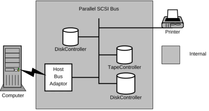
Figure 2-2: Devices Connected Using Parallel SCSI
many different varieties, however, the upper limit on the number of connected devices is never more than sixteen and the maximum length of cables is around 25 meters. Figure 2-2 shows a simple SCSI configuration with a few peripheral devices. Notice that the devices are connected to the parallel SCSI bus which is internal to the computer (with the exception of the printer). This configuration severely limits the number of devices that can be connected to a single computer.
In modern computing centers where petabytes of storage are required, these upper limits, imposed by parallel SCSI, are insufficient. With a maximum of sixteen peripherals per server, entire clusters of storage servers are often required to provide the desired storage capacity. With a limited distance of 25 meters, these storage servers must be in relatively close proximity, and alternative transport methods are required for backing up data to remote locations.
2.2
iSCSI
At the time that the SCSI protocol was created network bandwidth was considered a scarce resource and specialized I/O channels (such as parallel SCSI) were used for connecting computers to devices. Today, however, network bandwidth is plentiful and the need for
large amounts of data storage has grown. In order to respond to these changes a new set of technologies called storage area networks (SANs) have been created. In a storage area network, storage devices are connected to storage servers over external serial network hardware, instead of internal parallel I/O channels. The advantage of using networking technology instead of I/O channels is that networks allow for a much greater scalability. With a storage area network there is virtually no limit on the number of devices that can be connected to a storage server. Additionally there is much greater distance supported by networking technology, and networks can span a very large area.
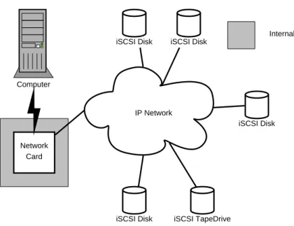
The Internet Small Computer System Interface (iSCSI) [12] protocol (which resides be-low SCSI on the protocol stack shown in Figure 2-1) was created as a cheaper alternative to the more expensive Fibre Channel technology that has, traditionally, been used to imple-ment SANs. The iSCSI protocol uses a standard TCP/IP network as the physical transport for the very well known SCSI command protocol. Since TCP/IP networks can have a limit-less number of connected devices and can span a, virtually, unbounded distance this enables SCSI to be used in a much more scalable environment. Figure 2-3 shows an iSCSI configura-tion. Notice that in this figure that the devices are all connected externally to the computer over a practically limitless network cloud. Another advantage of the iSCSI protocol is that IP networks are, currently, the most popular networking technology. This means that the hardware, equipment, tools and people with experience and knowledge about IP networks are readily available and are less costly than more specialized network fabrics.
The iSCSI protocol consists of iSCSIsessions between a target and an initiator device. Each iSCSI session can consist of multiple connections (mostly for redundancy and error recovery purposes), and each connection has three distinct phases: login phase,full feature phase andlogout phase. The login phase of an iSCSI connection is used for the initiator and target devices to authenticate and negotiate parameters that will be used for the remainder of the connection2
. After the login phase is complete the devices transition into a full
2
Computer
Network Card
IP Network iSCSI Disk iSCSI Disk
iSCSI TapeDrive iSCSI Disk
iSCSI Disk Internal
Figure 2-3: Devices Connected Using iSCSI
feature phase where SCSI commands and data are sent back-and-forth between the devices using iSCSI Command Protocol Data Units (PDUs) that contain embedded SCSI CDBs. Generally a connection will remain in the full feature phase for an extended period of time (the uptime of the computer, for example). When the devices are finished with their connection (typically when the initiator unmounts a disk or is shutdown) a simple logout exchange is performed.
2.2.1 Login Phase
The iSCSI login phase is used in order for the target and initiator to form a network connection, to communicate iSCSI specific parameters and, optionally, to authenticate each other. In this phase of a connection there are no SCSI CDBs transferred, instead special iSCSI PDUs are used. The login phase is for iSCSI only and would not take place in a SCSI session using a parallel SCSI bus as the physical transport.
During the login phase of an iSCSI connection, the initiator and target negotiate pa-rameters that will be used for a connection by exchanging iSCSI LoginRequest PDUs and
iSCSI LoginResponse PDUs. iSCSI LoginRequest PDUs are transmitted by the initiator device and each LoginRequest received by the target is responded to with an iSCSI Login-Response PDU. These special PDUs contain text strings that associate values with iSCSI parameters called keys. Both the initiator and target use these text strings to negotiate or declare certain values that will be used for the new connection. The iSCSI protocol defines a large set of negotiable parameter that can effect the performance, memory requirements and error handling a in given connection and/or session[14].
There are two types of iSCSI keys: declarative and negotiable. Declarative keys declare an un-negotiable value for an iSCSI parameter, for example the TargetAlias key is a declar-ative key in which the target declares a human-readable name or description that can be used to refer to it. An example of a negotiated key is the HeaderDigest key where the target and initiator offer a list of header digest algorithms (including “None” which, if selected, means that no header digest is used for this connection) that they support, and the most preferable algorithm that they have in common is selected. iSCSI keys can also have a variety of different types of values. Some keys, such as the HeaderDigest key, take a list of values in order with the most preferable first while others may take either a simple numeric value or a boolean value (“Yes” or “No”).
Keys in which the originator offers a list of values must always contain the value “None” in the list in order to indicate the lack of a certain functionality. When responding to a key where the value is a list, the responder must choose the first value in the list that it supports (since the “None” value is guaranteed to be in the list, it is always possible to respond to a list of values key, even if the functionality is not supported). To keys in which the originator offers a numeric range the reponder must reply with a single value that is within the given range. In the case of a numeric range, the key can either be a minimum function ormaximum function where the responder chooses either the minimum or maximum of the desired values respectively. Keys that contain boolean values are also negotiated based on one of two possible functions: AND andOR. With the AND function, if the originator offers the value “No” then the respondermust reply with the value “No”,
otherwise, the responder can reply with either value (“Yes” or “No”) depending on its desires or configuration. With the OR function, if the originator offers the value “Yes”, the responder must reply with the value “Yes”, otherwise, the responder can reply with either the value (“Yes” or “No”) depending, again, on its desires or configuration. These value types and negotiation functions give the administrator of an iSCSI environment a great deal of flexibility when deploying a storage network.
Once the initiator is finished negotiating all of its parameters, it sets the transition bit (or T-bit) of its next LoginRequest PDU to 1, and the next stage (NSG) field to the de-sired next stage in order to request a stage transition. The target is then able to continue negotiating parameters if it desires, or it can also set the T-bit and NSG field in its next LoginResponse PDU to transition to a new phase. Figure 2-4 shows a very simple iSCSI login phase where the devices do a single exchange of a set of key=value pairs and then transition to full feature phase (FFP). In Figure 2-4 the first LoginRequest/LoginResponse exchange is used to negotiate a set of required and optional iSCSI keys for the connec-tion. Both of these PDUs have the T-bit set to zero, which indicates that there is no state transition request. During an iSCSI Login phase there may be many more of these Login-Request/LoginResponse exchanges, in order to allow the devices to negotiate more keys, or to perform authentication during a special security negotiation phase (which may be tran-sitioned to using the T-bit and NSG field). In the second LoginRequest in Figure 2-4, the initiator sets the T-bit to one and the next stage field to full feature phase to tell the target that it is ready to make a stage transition. The target replies with a LoginResponse with the T-bit also set to one and the next stage field set to full feature phase, which accepts the transition and the devices proceed into the full feature phase of the iSCSI connection.
2.2.2 Full Feature Phase
The iSCSI full feature phase is where the devices transfer encapsulated SCSI commands and data. During full feature phase the initiator creates and transmits iSCSI Command PDUs which contain SCSI CDBs that were generated by the SCSI initiator layer and passed down
Target Initiator
LoginRequest (T=0)
LoginResponse (T=0)
LoginRequest (T=1, NSG=FFP)
LoginResponse (T=1, NSG=FFP)
Full Feature Phase
Figure 2-4: A Simple iSCSI Login
to iSCSI for transport. For each iSCSI Command PDU which is received by the target, the target will perform a service for the initiator (which may involve a data transfer in either direction) and will conclude the service with an iSCSI Response PDU that contains the SCSI response and status (typically either 0x00 for success or 0x02 for an error).
Certain SCSI Commands may make use of an optional data transfer phase. For example, in a SCSI READ or SCSI WRITE command data will be transferred to or from the initiator respectively. Since iSCSI target devices are expected to be peripherals with limited resources (such as an iSCSI enabled disk controller), all data transfers are controlled by the target. For READ commands, the target device sends iSCSI Data-In3
PDUs to the initiator device. Since the target is sending the data in this situation there is no special handling required,
3
The direction of SCSI and iSCSI commands are relative to the initiator device. Therefore, the Data-In PDU issent by the target andreceivedby the initiator. Likewise, Data-Out PDUs aresent by the initiator
Target Initiator iSCSI/SCSI READ iSCSI DataIn iSCSI DataIn iSCSI DataIn iSCSI DataIn iSCSI/SCSI Response
Figure 2-5: An iSCSI Encapsulated SCSI READ Command
the target has control of the transfer by default since it can select how much and how fast to send its PDUs. Figure 2-5 shows an iSCSI READ. In this figure, the initiator begins the read by sending an iSCSI encapsulated SCSI READ command to the target, the target then sends the read data to the initiator using Data-In PDUs and finishes the command with an iSCSI encapsulated SCSI response. This response tells the initiator that the read is complete. For WRITE commands a special Ready2Transfer (R2T) PDU is used for the target to signal to the initiator that it is ready to receive a set of Data-Out PDUs containing the data being written. R2T PDUs allow the target to maintain control over when the data is transferred and how much data is transferred at a time. Figure 2-6 shows an iSCSI WRITE with two R2T PDUs.
In order to allow the devices to have better control over the flow of data, all iSCSI data transfers happen in bursts of a certain size called MaxBurstLength (which is negotiated during the connection login phase). For READ commands, where the target sends a set of Data-In PDUs to the initiator, the bursts are not noticeable since one burst is immediately
Target Initiator iSCSI/SCSI WRITE iSCSI R2T iSCSI DataOut iSCSI/SCSI Response iSCSI DataOut iSCSI DataOut iSCSI R2T iSCSI DataOut
Figure 2-6: An iSCSI Encapsulated SCSI WRITE Command
followed by the next. For WRITE commands, however, the MaxBurstLength defines the maximum size of data that can be requested by a single R2T PDU. In Figure 2-6 the highlighted PDUs makeup a single data burst. In this figure there are two bursts of Data-Out PDUs, which are dictated by the R2Ts transmitted by the target. Additionally, the MaxRecvDataSegmentLength parameter (again negotiated during the login phase) dictates the maximum size of a single Data-In or Data-Out PDU. This means that any given burst of data may contain M axRecvDataSegmentLengthM axBurstLength Data-In or Data-Out PDUs. Previous work has been done to evaluate these values and other negotiable values that iSCSI offers to see what their effect is on performance [14].
2.2.3 Logout Phase
When the initiator has finished with a connection, it sends an iSCSI LogoutRequest PDU to the target. Upon receiving a LogoutRequest the target device will respond with an iSCSI
LogoutResponse PDU and the devices will tear down the connection.
2.3
RDMA
The speeds of networking technologies in today’s high-performance computing environments are rapidly growing. In high-end systems, the CPU has replaced the network as the new “bottle neck”. With technologies like 10 Gigabit/sec Ethernet (10GigE) modern CPUs lose the ability to keep enough data flowing into the network to make full use of the available bandwidth. With a reliable transport system like TCP, the operating system must make and retain copies of all outgoing data so that it is able to retransmit it if the data does not make it, without error, through the network to its destination. On the receiving side, the operating system must maintain a reassembly buffer where, possibly out of order, data is stored before being copied into the final receive buffer. In addition to all of the overhead involved in copying data, the operating system is constantly interrupted each time a new segment of data arrives on the network. At each network interrupt, the operating system must copy the data off of the network card and process the header information to determine how to interpret the data. With all of this interrupting, copying and processing a typical CPU is only able to make use of about half of a 10GigE connection. Not only is the CPU insufficient to use all of the available bandwidth, but it also must spend a lot of its time maintaining the network traffic instead of handling other processing that the system may need done.
To fix the problems stated above, specialized Remote Direct Memory Access (RDMA) hardware has been developed to alleviate the need for data copying, and to offload network processing from the CPU. In an RDMA protocol auxiliary information travels across the network with the data so that it can be immediately placed in its final receive buffer. Along with this auxiliary information, specific segment sizing and special markers can be used to allow detection of packet boundaries to eliminate the need for a lot of reassembly in the case of out of order data. These two features allow RDMA hardware to perform “zero-copy”
transfers directly from the memory of one computer to the memory of another.
Although there are other RDMA technologies (such as Infiniband), the one that we are mostly concerned with for this project is iWARP [4] [13] [11]. iWARP is a protocol suite that allows for RDMA across a TCP/IP network (such as those used with iSCSI). The iWARP protocol suite is divided into three different protocols:
1. Marker PDU Aligned Framing (MPA) [4]
2. Direct Data Placement (DDP) [13]
3. Remote Direct Memory Access Protocol (RDMAP) [11]
2.3.1 Marker PDU Aligned Framing
Since TCP is a stream oriented protocol, upper layer protocols (ULP)4
, that require the detection of record boundaries, must use a reassembly buffer to store received TCP infor-mation while looking for message boundaries. If the header inforinfor-mation of an upper layer frame arrives late (due to lost or out of order TCP segments), it will be necessary for the ULP to delay processing of all subsequent TCP segments until the one containing the header arrives. This is because the ULP will not be able to determine where the next frame begins since that information is contained in a header that has not yet arrived.
The MPA protocol resides directly above the TCP layer in the protocol stack (refer to Figure 2-1) . MPA defines a method of reliably tracking frame boundaries within a TCP stream by using fixed sized frames and by optionally embedding markers at known offsets in a TCP stream. Using MPA on top of TCP provides the upper layer protocol with a method of sending fixed sized records which,in the optimal case, will arrive intact embedded within a single TCP segment. With Marker PDU Aligned Framing a receiver is not required to
4
The term upper layer protocol refers to any protocol that resides above the current protocol on the stack shown in Figure 2-1. In the case of MPA, the upper layer protocol refers to DDP. In the case of DDP, the upper layer protocol refers to RDMAP. Finally, in the case of RDMAP, the upper layer protocol refers to any protocol that is making use of the RDMA stack in order to gain high-performance network usage.
reassemble data from the TCP stream, which allows an ULP (such as DDP) to have the ability to skip using intermediate storage and to directly place received data into memory. In addition to providing fixed sized framing, the MPA protocol also provides padding for 4-byte alignment and an optionalcyclic redundancy check(CRC). The CRC can be used in order to determine if the received packet has been modified during transmission. The purpose of the CRC in the MPA layer is to provide extra checking for errors that may have been missed by the TCP layer. If the CRC option is not enabled, the MPA header still contains the CRC field, it is just left unused.
In practice, the MPA markers and CRCs are not used. In, what the MPA specification refers to as an optimal situation, the MPA layer works very closely with the TCP layer in order to guarantee that each MPA frame will be contained in a single TCP segment. In this optimal case, MPA markers provide little benefit, since reassembly is never needed to reconstruct an MPA frame. In current hardware, this optimal case is implemented and markers would only add extra overhead. Additionally, the optional MPA CRCs are also unused in current hardware.
2.3.2 Direct Data Placement
Above the MPA layer in the iWARP stack (see Figure 2-1), is the Direct Data Placement protocol (DDP). DDP allows an upper layer protocol (such as RDMAP) to send data directly to a destination receive buffer without the need for an intermediate copy. DDP works with MPA to segment data into small frames where each frame will fit directly into a single TCP segment. Using DDP with MPA allows for frames to be directly placed in the receiver’s memory without the need for buffering or reassembly even when TCP segments are lost or arrive out of order. Without the use of MPA framing, lost or out of order TCP segments would require DDP to use reassembly storage in order to reconstruct the frames and find the header with the memory placement information. Figure 2-7 shows a theoretical DDP frame that does not use MPA. Each block in this figure represents a TCP segment. Notice that if the TCP segment labeled “A” does not arrive first, the other segments must
TCP Segment DDP Header A B C D
Figure 2-7: A Theoretical DDP Frame Without MPA
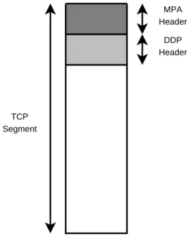
be buffered until segment “A” arrives with the DDP header. Figure 2-8 shows what a DDP frame using MPA would look like5
. Notice that the entire DDP frame fits into just a single TCP segment, so even if one is lost there is always a DDP header available in the next. This is the ideal behavior of TCP, MPA and DDP, depending on the implementation, MPA frames may not fit exactly into a single TCP segment. In these situations, the MPA stream markers can be used to help detect frame boundaries in the case of packet loss.
DDP provides two different mechanisms to its upper layer for transferring data: Tagged Buffer transfers andUntagged Buffer transfers. In a tagged buffer transfer, the upper layer protocol must advertise the buffer that will be used in the transfer to its peer. The peer then has the ability to perform a direct, memory-to-memory transfer into the advertised buffer. For untagged buffer transfers, the receiver must explicitly post untagged receive buffers on a queue for the peer to write data to. These buffers are posted in the order that
5
Note that the size of the single TCP segment shown in Figure 2-8 would be the same size as the smaller segments (labeled A-D) in Figure 2-7, however Figure 2-8 is enlarged to show the headers more clearly.
TCP Segment DDP Header MPA Header
Figure 2-8: A DDP Segment Using MPA
the receiver would like them to be consumed by the RDMA hardware upon receiving an untagged transfer. Untagged transfers also require the upper layer to perform flow control, since a transfer will fail if there is not an appropriately sized receive buffer available at the front of the queue to accept an incoming message.
DDP uses the termdata sink to refer to the the destination of a data transfer and the termdata source to refer to the source of a data transfer. DDP also defines the notion of a Steering Tag (Stag) which is an opaque identifier for a tagged buffer. When performing a tagged buffer transfer, the data source uses the Stag from the data sink to transfer data directly into the data sink buffer. In order for the data source to know the Stag of a data sink buffer, an upper layer protocol at the data sink is required to advertise the Stag along with a Tagged Offset (TO) and a length for the desired transfer. In untagged buffer transfers the data source sends a message to the “next” untagged buffer on the front of the untagged buffer queue at the data sink. It is the job of the upper layer protocol on both the data sink and the data source to ensure that the data sink has enough queued buffers to be able
to receive the untagged transfer.
2.3.3 Remote Direct Memory Access Protocol
The Remote Direct Memory Access Protocol (RDMAP) [11] uses DDP to provide remote direct memory access over TCP/IP networks and other reliable transports. RDMAP is also designed to allow for kernel bypass, in which a user-space process bypasses the operating system kernel when performing data transfers. Kernel bypass is possible because the entire network stack (RDMAP, DDP, MPA, TCP, IP and Ethernet in Figure 2-1) is offloaded onto the RDMA hardware. A user-space application, with access to the RDMA hardware is able to make network connections and send data without any interaction with the operating system kernel. Kernel bypass allows a user process to avoid the extra context switches and data copies that are usually involved when communicating through the kernel.
RDMAP defines a set of data transfer operations which are summarized below [11]:
Send uses an untagged DDP data transfer in order to send information from a data source to an untagged data sink buffer on the receiver side. When using a Send operation the upper layer protocol at the data source provides a message and a length to send to the data sink. At the data sink side, after receiving the data from a Send operation, the upper layer protocol is provided with the length and the received message.
Send with Invalidate (SendInv) uses an untagged DDP transfer, just like the Send op-eration. However, in a SendInv message an additional Stag in the header is transfered to the receiver. After the receiver gets the data from the SendInv message, it invali-dates the use of the buffer that is identified by the extra Stag field (which is a separate buffer from the one that is receiving the data transmitted with this send operation).
Send with Solicited Event (SendSE) uses an untagged DDP transfer, just like the Send operation, but after receiving the data in the data sink buffer, it also gener-ates an event in the receiver side.
Send with Solicited Event and Invalidate (SendInvSE) is a combination of Send-Inv and SendSE. After the receiver gets the data, it invalidates the buffer identified by the extra Stag and generates an event on the receiver side.
RDMA Read uses a tagged DDP transfer in order to perform a zero-copy read from a remote data source buffer. The RDMA Read operation uses a two message exchange in order to perform the data transfer. First, the data sink sends, to the data source, an RDMA ReadRequest message which contains the<Stag,TO,len>tuple that describes the data source buffer, and the <Stag,TO,len> tuple that describes the data sink buffer. After receiving the RDMA ReadRequest message, the data source will send a RDMA ReadResponse message to the data sink which performs the zero-copy transfer from the data source buffer to the data sink buffer. On the data sink side, the upper layer protocol provides the RDMAP layer with the data source buffer’s Stag, Tagged Offset and length and the data sink buffer’s Stag, Tagged Offset and length. The upper layer protocol on the data source is not notified of an RDMA Read operation performed by the remote peer.
RDMA Write uses a tagged DDP transfer to write data from the data source buffer directly into the data sink buffer on the remote peer. On the data source side, the upper layer protocol provides the RDMA layer with the data sink buffer’s Stag, Tagged Offset and with a message and message length. The upper layer protocol on the data sink is not notified of a RDMA Write operation performed by the remote peer.
Terminate uses a DDP untagged transfer to send error information to the remote peer.
These data operations are provided to users to allow them to access the functionality of RDMA hardware. The exact means used to provide these seven operations is left open in order to facilitate compatibility with a large range of systems.
2.4
iSER
In order for iSCSI to compete with other SAN technologies, which have the ability to perform at speeds that are greater than 1 Gigabit/sec, it must be able to make efficient use of 10GigE. To this ends, the iSCSI Extensions for RDMA (iSER) [8] protocol was created. iSER is an implementation of the Datamover Architecture (DA) for iSCSI [3]. DA specifies operations that a small protocol layer, residing below iSCSI on the protocol stack (see Figure 2-1), needs in order provide a standardized interface for iSCSI to transfer commands and data over a network. The iSER extensions specify an implementation of DA that encapsulate and translate iSCSI PDUs in order to send them over an RDMA Capable Protocol (RCaP), such as iWARP, while retaining a minimal amount of extra state information.
2.4.1 iSER Operational Primitives
The Datamover Architecture for iSCSI defines a set of operational primitives that must be provided to the iSCSI layer. iSER describes an implementation of these operational primitives that allow for using an RCaP layer as the transfer method. There are nine operational primitives that an iSER layer will provide for iSCSI.
Send Control operational primitive is used by an iSCSI initiator and target device to request the transfer ofiSCSI Control type PDUs which are iSCSI PDUs that contain either iSCSI/SCSI commands or unsolicited Data-Out PDUs. Depending on the type of iSCSI Control PDU that is being sent, a different RDMA Send-type operation is used:
iSCSI Command PDUs sent by the initiator are transferred using RDMA Send with Solicited Event operations. If the Command PDU will require an optional data transfer phase, the iSER layer at the initiator will advertise an Stag to the target for the data sink or data source buffer (depending on the direction of the transfer) to be used.
iSCSI Response PDUs sent by the target are transferred using an RDMA Send with Solicited Event operation unless the Response is responding to an iSCSI Command PDU that involved a data transfer where an Stag was advertised; in this case a Send with Solicited Event and Invalidate operation is used to automatically invalidate the Stag used for the completed data transfer.
iSCSI Data-Out PDUs sent by the initiator for unsolicited data transfers are trans-ferred using a Send operation with the exception of the final Data-Out PDU in a burst which is transmitted with the SendSE operation instead.
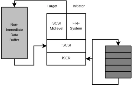
Put Data is an operational primitive that is used only by the target. This operational primitive is used to send an iSCSI Data-In PDU. The iSER layer at the target trans-lates the Data-In PDU, received from the local iSCSI layer, into an RDMA Write operation using the Stag that was advertised by the initiator in the iSCSI Command PDU that requested the data transfer. The data is written using a zero-copy transfer directly into the initiator’s data sink buffer.
Get Data is an operational primitive that is used only by the target. This operational primitive is used to send an iSCSI Ready2Transfer (R2T) PDU. The iSER layer at the target translates the R2T PDU, received from the local iSCSI layer, into an RDMA Read operation using the Stag advertised by the initiator in the iSCSI Command PDU that requested the data transfer. The RDMA Read from the target will perform a zero-copy read of the data from the initiator’s data source buffer into the data sink buffer on the target.
Allocate Connection Resources is used by the initiator and the target iSCSI layer to tell the iSER layer to allocate connection specific resources that it will need for an RDMA session.
Deallocate Connection Resources is used by the initiator and the target iSCSI layers to tell the iSER layer to deallocate any resources that it has allocated for a given
connection.
Enable Datamover is used by the target and the initiator in order for the iSCSI layer to tell the iSER layer that it should enable iSER-assisted mode on the given connection.
Connection Terminate is used by the initiator and the target iSCSI layers to tell the iSER layer to terminate the RDMA connection.
Notice Key Values is used by the initiator and the target to allow the iSER layer to see the result of iSCSI Login key=value text negotiations. The iSER layer can then use some of the information from these negotiations to allocate the appropriate amount of resources for this connection.
Deallocate Task Resources is used by the initiator and the target to allow the iSER layer to free up resources that it has allocated for a specific iSCSI task.
Along with the operational primitives provided by the iSER layer to iSCSI, there is another set of operational primitives that the iSCSI layer must provide to iSER. These primitives are used as call backs for iSER to signal the local iSCSI layer of various events.
Control Notify is used by the iSER layer to signal to the iSCSI layer that a new iSCSI Control type PDU has been received. iSCSI Control type PDUs, as described above, are the iSCSI PDUs that contain iSCSI specific commands, SCSI commands or unso-licited Data-Out PDUs.
Data Completion Notify is used by the iSER layer on the target to notify the iSCSI layer that a data transfer (either an RDMA Read or an RDMA Write) has completed.
Data Ack Notify is used by the iSER layer at the target to notify the iSCSI layer of an arriving data acknowledgment.
Connection Termination Notify is used by the iSER layer to notify the iSCSI layer of an unexpected connection termination.
2.4.2 iSER Specific iSCSI Login/Text Keys
The iSER extensions also specify a few additional iSCSI Login/Text keys used to negotiate iSER specific parameters.
RDMAExtensions is a boolean type key that is added by iSER to the iSCSI Login phase. This optional key must be negotiated to “Yes” by both the initiator and target in order to operate in iSER-assisted mode.
TargetRecvDataSegmentLength and InitiatorRecvDataSegmentLength keys are numeric keys that are added by iSER to the iSCSI Login phase. The values of these keys declare the maximum number of bytes that either the target or initiator can receive in a single iSCSI Control type PDU. These two keys are part of the flow control mechanism that iSER uses for RDMA untagged transfers. The values of these keys corresponds to the size of the untagged buffers that are queued with the RCaP layer.
MaxOutstandingUnexpectedPDUs declares the maximum number of outstanding, un-expected PDUs that a device can receive. This key is also used in order to help with flow control of RDMA untagged transfers. This parameter corresponds to the number of untagged buffers that are queued with the RCaP layer.
2.4.3 iSER Inbound/Outbound RDMA Read Queue Depths
In addition to flow control for untagged buffers, the iSER layer is also responsible for flow controlling RDMA ReadRequests. When performing RDMA Read operations, an RCaP layer must have the appropriate amount of resources to handle all of the possible RDMA ReadRequest messages that the remote peer may send. In the case of iSER, only the target will be sending RDMA ReadRequests, therefore the initiator declares the maximum depth of the Inbound RDMA Read Queue (IRD). The iSER layer at the target is then able to select a maximum depth of the Outbound RDMA Read Queue (ORD) which is at most
as large as the IRD. If the ORD value proposed by the target is less than the IRD value declared by the initiator, the initiator may choose to free up the extra resources. These parameters are negotiated in an additional Hello message exchange that is performed in iSER-assisted mode as described in Section 2.4.5.
2.4.4 iSER Connection Setup
An iSER-assisted iSCSI session is established by first performing a standard iSCSI login in regular TCP streaming mode. During the login phase, if both of the devices negotiate RDMAExtensions=Yes, then the following full feature phase will use the iSER extensions and RDMA. The RDMAExtensions key must be offered in the first available LoginRe-quest or LoginResponse PDU in order to allow the devices to negotiate the additional iSER parameters on a successful RDMAExtensions negotiation. A failure to negotiate the RD-MAExtensions key to “Yes” will cause the devices to fallback on traditional, unassisted, iSCSI in the proceeding full feature phase.
On the iSCSI initiator, the Allocate Connection Resources operational primitive is invoked on the iSER layer just before sending a LoginRequest with the T-bit set for transition into full feature phase. The initiator, then has the option of invoking the
Notice Key Valuesprimitive, before invoking theyAllocate Connection Resources prim-itive, to allow the iSER layer to see the results of the login phase negotiations. After re-ceiving the target’s LoginResponse message with the T-bit set for full feature phase, the initiator must invoke theEnable Datamover primitive in order to transition the TCP con-nection from streaming mode into iSER-assisted mode.
On the iSCSI target, theAllocate Connection Resourcesoperational primitive must be invoked on the iSER layer just before sending a LoginRepsonse with the T-bit set in, in response to the initiator’s request to transition into full feature phase. As with the initiator side, the target can optionally invoke the Notice Key Values primitive to allow the iSER layer to see the results of the login phase negotiations. The target must invoke the
set to complete the transition to full feature phase and to transition the TCP connection into iSER-assisted mode.
2.4.5 iSER Hello Message Exchange
Directly after entering full feature phase of the iSCSI connection the initiator must send an iSER Hello message to the target declaring the iSER-IRD (the maximum number of outstanding Read Requests that the RCaP layer at the initiator is prepared to receive). In response to the Hello message, the target must send the initiator a HelloReply message declaring the iSER-ORD (the maximum number of outstanding Read Requests that the iSER target is prepared to send to the initiator) that will be used for the connection. Upon receiving the HelloReply message from the target, if the iSER-ORD value is lower than the iSER-IRD value, the initiator may free up any extraneous resources. Once the Hello message exchange is completed, the devices are successfully operating in an iSER-assisted iSCSI full feature phase where commands and data are transmitted as described in Sections 2.4.7 and 2.4.8.
2.4.6 iSER Connection Termination
In a normal logout, the iSCSI layer at the initiator uses theSend Controloperational prim-itive to send an iSCSI LogoutRequest PDU to the target. After receiving the iSCSI Lo-goutRequest, the target responds with an iSCSI LogoutResponse (using theSend Control
operational primitive), and then invokes theConnection Terminateprimitive to notify the iSER layer that it should close the RCaP stream. After the initiator receives the iSCSI LogoutRespsonse from the target, it also invokes the Connection Terminate operational primitive on its end to notify its iSER layer that it should terminate the RCaP stream.
2.4.7 iSER-Assisted iSCSI Read Operation
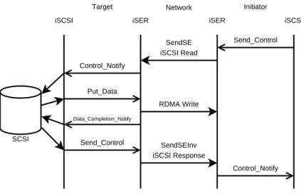
Figure 2-9 shows an iSER-assisted iSCSI Read operation. In this figure, the initiator invokes theSend Controloperational primitive on its local iSER layer to request the transmission
iSCSI iSCSI iSER iSER
Target Initiator Send_Control SendSE iSCSI Read Control_Notify Put_Data RDMA Write Data_Completion_Notify Send_Control SendSEInv iSCSI Response Control_Notify SCSI Network
Figure 2-9: An iSER-Assisted iSCSI Read
of an iSCSI Command PDU encapsulating a SCSI Read CDB. When the iSER layer at the target receives the Command PDU, it generates a Control Notifyevent at the target iSCSI layer to notify it of the received iSCSI Command. After passing the Read CDB off to the SCSI layer and acquiring the read data buffer, the iSCSI target invokes thePut Data
operational primitive on its local iSER layer to transfer the read data to the data sink buffer on the initiator using a zero-copy RDMA Write operation. This entire RDMA Write operation happens without intervention of the CPU on either end. Once the RDMA Write operation completes the iSER layer at the target notifies the iSCSI layer by invoking the
Data Completion Notify operational primitive on the target-side iSCSI layer. When the target SCSI layer has been notified that the data transfer is complete, the target iSCSI layer invokes the Send Controloperational primitive in order to tell the target-side iSER layer to transmit an iSCSI Response PDU. After receiving the iSCSI Response PDU, the initiator’s iSER layer notifies the iSCSI initiator by invoking theControl Notifyprimitive and the transfer is completed. Notice that a Read at the SCSI/iSCSI layer is implemented by an RDMA Write operation.
iSCSI
iSCSI iSER iSER
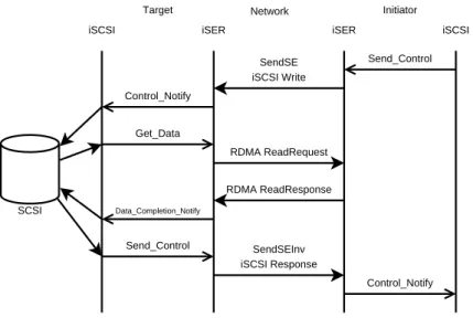
Target Initiator Send_Control SendSE iSCSI Write Control_Notify Get_Data RDMA ReadRequest Data_Completion_Notify Send_Control SendSEInv iSCSI Response Control_Notify RDMA ReadResponse SCSI Network
Figure 2-10: An iSER-Assisted iSCSI Write
2.4.8 iSER-Assisted iSCSI Write Operation
Figure 2-10 shows an iSER-assisted iSCSI Write operation. To begin the Write operation, the initiator invokes the Send Control operational primitive on its local iSER layer to transmit an iSCSI Command PDU encapsulating a SCSI Write CDB. Upon receiving the iSCSI Command PDU, the target-side iSER layer invokes theControl Notifyoperational primitive on the target iSCSI layer to notify it of the received command. The iSCSI layer on the target passes the CDB to the target SCSI level, and then uses theGet Dataoperational primitive to tell the target-side iSER layer to read the data from the data source buffer on the initiator. The iSER layer at the target transmits an RDMA ReadRequest to the ini-tiator RDMA layer which responds with an RDMA ReadResponse message containing the Read Data. The RDMA ReadRequest and ReadResponse messages are exchanged without the intervention of the CPU on either end and the data is transferred without using any extraneous copies. Once the target side RDMA layer is finished placing the Read data, the iSER layer notifies the iSCSI layer at the target using theData Completion Notify opera-tional primitive. The target iSCSI layer notifies the target SCSI layer that the data transfer has completed, and then uses theSend Controlprimitive to have an iSCSI Response PDU
sent to the initiator. When the initiator’s iSER layer receives the iSCSI Response PDU it notifies the iSCSI layer using theControl Notify primitive and the transfer is completed. Notice that a Write at the SCSI/iSCSI layer is implemented by an RDMA Read operation.
2.4.9 iSER and Current RDMA Hardware
With current iWARP hardware, the iSER specification is not possible to follow as stated. Specifically, current RDMA hardware does not perform “TCP stream transitioning”, “Zero-based virtual addressing” or the Send with Solicited Event and Invalidate operation. These three issues are discussed in detail in Sections 3.6.1 3.6.2 and 3.6.3 respectively. The iSER implementation discussed in this thesis uses a set of extended operational primitives in order to aid in the establishment of RDMA connections. Additionally, a non-standardized iSER header is used in order to communicate extra information that is required by current RDMA hardware in order to perform RDMA data transfers. Finally, since the Send with Solicited Event and Invalidate operation is not supported, our implementation uses a Send with Solicited Event operation in order to transmit iSCSI/SCSI response PDUs.
CHAPTER 3
IMPLEMENTATION
In order to perform our comparisons between iSER-assisted and traditional iSCSI, we first needed to build a working iSCSI-iSER-iWARP stack. Due to the complexity of each layer in this stack, we choose to base our work on preexisting implementations instead of creating our own where possible. This process involved selecting from various software projects to use as a base, and the reworking them to fit our needs.
3.0.10 Protocol Layers
The software layers that we choose to use for this project are:
• The University of New Hampshire iSCSI Reference target and initiator (UNH-iSCSI).
• The OpenFabrics Alliance (OFA) [1] RDMA stack (for communication with the RDMA
hardware). We also made use of a software-only implementation of the iWARP pro-tocol developed at the Ohio Super-Computer Center (OSC) which provides an OFA-compatible interface [6].
• An old iSER implementation from the OpenIB iSER target project [15].
Figure 3-1 shows how all of the protocol layers fit together with iSCSI and the iSER extensions. The following sections describe how each of these layers work and interact with the pieces that sit above or below it in the protocol stack. Additionally, a description of the modifications that were required and any difficulties that were encountered is given.
UNH-iSCSI iSER OSC iWARP IB TCP IP Ethernet OFA CMA Software protocols Hardware protocols iWARP
Figure 3-1: iSCSI-iSER-RDMA Stacks.
3.1
iSCSI
In order to create a working iSER solution, we first decided to choose an iSCSI implemen-tation to which we would add iSER support. There are a handful of freely available iSCSI implementations for the Linux operating system. We selected one that was created here at the University of New Hampshire InterOperability Lab (UNH-iSCSI) [9]. There are a number of reasons for this choice:
• The UNH-iSCSI implementation was created and is maintained here at the
InterOp-erability Lab (IOL) at the University of New Hampshire, which makes it very easy to get support for the project. Most other projects would require a lot of support from external organizations.
• UNH-iSCSI contains both an iSCSI initiator and target together in one project. Both
build either an iSCSI initiator or a target, not both. This could lead to interoperability issues between the two separate implementations.
• Previous work has already been done to add iSER support to UNH-iSCSI [10]. While
there are other projects available that are developing or are thinking about developing iSER, the UNH-iSCSI project already had some preliminary hooks for iSER that were added during this previous, incomplete attempt.
3.1.1 Three Steps
The iSCSI project was developed as a Linux kernel module, which means that UNH-iSCSI code runs in kernel-space. Kernel-space code is much more difficult to debug than user-space code because the user-space is provided with memory protection. A mistake made in kernel-space can bring down an entire system, whereas a mistake made in user-space will, at most, abort the process that caused the error. In addition to memory protection, user-space code can be easily run in a debugger which can provide line-by-line stepping and can give stack-traces when errors are encountered.
Since the Open Fabrics Alliance RDMA stack, which we choose to use for communicating with the RDMA hardware, provides a user-space API in addition to a kernel-space API and since user-space programs are much easier to debug, and therefore to develop, than kernel modules we decided to use three steps in our implementation.
1. Move UNH-iSCSI into user-space.
2. Add support for iSER-assisted iSCSI, in user-space.
3. Move everything back into the Linux kernel.
3.1.2 Emulating the Kernel-Space APIs
The first step in our implementation was to move the UNH-iSCSI project into the Linux user-space. As described above projects that run in user-space are much easier to develop
than projects in kernel-space. In user-space we are provided with an almost limitless set of tools such as the GNU Debugger gdb, the valgrind profiler and more. The process that we used to move our project out of the kernel and into the Linux user-space is described below.
In Linux, the kernel-space code is not able to make use of traditional user-space libraries. This is partially because the kernel implements most of the library functionality on behalf of user-space. Another reason that the library functions in the kernel are different is because the kernel does not see the same virtual view of the computer hardware that user-spaces processes do. The kernel has the ability to use some shortcuts that would be impossible in user-space (such as direct access to the hardware without an abstraction layer). The main task that we did in order to move UNH-iSCSI into user-space was to emulate a large set of functions traditionally provided by the Linux kernel using only user-space functionality.
In order to properly mimic the kernel-space libraries, we attempted to use as much code directly from the Linux kernel as possible. Specifically, we were able to use the Linux kernel doubly-linked list and atomic t (a structure which defines a multiprocessor atomic counter) data types directly from the source code of the kernel. We were also able to make use of the Linux bit-wise operation functions and some other utility routines directly. Other higher level structures, such as threading and semaphores, we were not able to copy directly.
To build the API for pieces that we were not able to pull directly out of the kernel source code, we needed to implement them in terms of user-space functions. To handle threading, we used the POSIX threads library. This library provides an API for creating and manipulate new, concurrent threads of control. Since UNH-iSCSI is mostly event driven, it relies heavily on threads in order to wait for events from multiple sources (such as receiving on the network, transmitting on the network, the SCSI mid-level and more). The use of threads also requires locking primitives to prevent race conditions when multiple threads are attempting to access common data at the same time. The Linux kernel is heavily parallelized and has a very rich set of tools for maintaining concurrent threads and preventing race conditions. To reimplement the Linux locking primitives required us to
use more features of the POSIX threads library, such as conditional waits and mutex data structures.
An example of another major structure that the Linux kernel provides that is not typi-cally found in user-space are memory caches. The kernel has a set of functions for creating a cache of similarly sized memory regions that are used for very quickly allocating commonly used structures. In order to provide this functionality in user-space, we were required to implement our own simple memory cache using a list of pre-allocated memory chunks.
Finally, there were a few pieces of the kernel API that, when translated to user-space were “no-ops”. An example of this is the translation between virtual and physical addresses. In the kernel-space, certain operations require a translation between a virtual memory address and a physical memory address (such as DMA transfers). In user-space there is never a need to use physical memory addresses, so these routines were translated into routines that, effectively, do nothing.
3.1.3 Moving to User-Space
The UNH-iSCSI target was the first piece we moved to user-space. The target is able to act in three different modes: DISKIO mode1
,FILEIO mode2
andMEMORYIO mode3
. Of these three modes, only the DISKIO mode is required to be in kernel-space. In DISKIO mode, the target sends SCSI commands straight into the Linux SCSI mid-level, an operation that can only happen from within the kernel. In the other two modes (FILEIO mode and MEMORYIO mode) the target does not need to be in kernel-space at all. This design allows
1
The target uses a SCSI disk for storage. DISKIO mode allows the target to provide raw access to a real SCSI disk drive.
2
The target uses a file on its local file system to emulate a disk drive. This allows the target to be used in a system that does not have a SCSI disk available. It also allows for debugging the iSCSI implementation without causing any harm to SCSI disks in the target system.
3
The target uses a memory buffer instead of a disk. This mode allows the iSCSI stack to be tested without worrying about the overhead of the Linux file system.
the target piece to be moved to user-space without significant changes as long as it is not compiled with DISKIO mode support.
The UNH-iSCSI initiator required more work to get it to run in user-space. Since the initiator receives commands directly from the Linux SCSI mid-level4
it required some redesigning to move it out of the kernel. In order for the initiator to act like a real SCSI initiator device, we needed to devise a way to pass it SCSI commands that it could then transfer to the target. To accomplish this, we wrote a simple interpreter for the initiator. This interpreter reads commands from standard input and performs basic actions like: logging into a target with a new iSCSI connection, sending a SCSI command to the target, and perform a SCSI READ or WRITE operation. This simple interpreter allows us to write scripts that emulate a real SCSI session. In addition to emulating a SCSI session, these scripts collect timing information to determine the performance of transfers.
Timing information, in the user-space initiator, is gathered by using a special repeat
command. The repeat command specifies a RepeatCount and an output file to log to. Following a repeat command can be either a SCSI READ or SCSI WRITE operation. The
repeat command tells the interpreter to perform the following operation RepeatCount times while keeping track of the total number of bytes transferred and the time that the entire transfer takes. Once the repeated operations are completed the command logs the RepeatCount,number of bytes transferred and total transfer time (in seconds) to the spec-ified output file. In order to prevent memory exhaustion, the user-space initiator uses a very simple flow control mechanism when building and queuing new SCSI commands with the iSCSI layer. Therepeatcommand tracks command completions and makes sure that it never queues more than a certain number of SCSI command with the iSCSI layer. If this mechanism were not in place, our emulated sessions would not be able to use aRepeatCount that would transfer more bytes than the physical memory of the host computer.
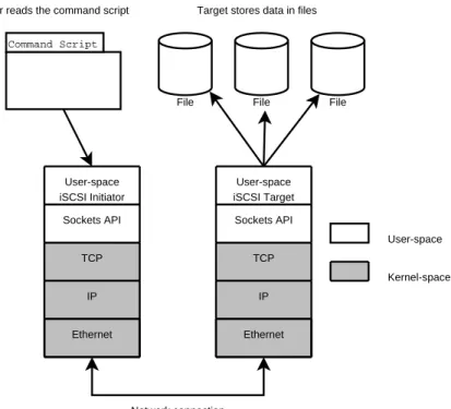
Figure 3-2 depicts a possible configuration for the user-space iSCSI system. This diagram
4
User-space iSCSI Target TCP IP Ethernet Kernel-space Sockets API User-space User-space iSCSI Initiator TCP IP Ethernet Sockets API Command Script File File File Network connection
Initiator reads the command script Target stores data in files
Figure 3-2: User-space iSCSI Implementation
shows the initiator reading from a command script, and a target that is in FILEIO mode using local files as its backing data store. Alternatively the user-space target could use a memory buffer instead of files (MEMORYIO mode), which would allow us to evaluate the performance of the transfer protocols without the overhead of an actual storage system.
3.2
RDMA Interfaces
To have the ability to communicate with RDMA hardware, there are a handful of RDMA interfaces that provide POSIX socket-like abstractions. This type of abstraction is advan-tageous because most programmers are very familiar the socket communication paradigm. A group called the OpenFabrics Alliance (OFA) provides a free RDMA stack with a socket-like abstraction layer that they call a Communication Manager Abstraction (CMA), along with a verbs layer that is used to perform data transfers (together these pieces are referred to as the OFA stack or the OFA API). The OFA stack has been growing in popularity