©
2015
European Nuclear Society
Avenue des Art 56
1000
Brussels, Belgium
Phone + 32 2 505 30 54
Fax +32 2 502 39 02
E-mail [email protected]
Internet www.euronuclear.org
ISBN
978-92-95064-23-2
The content of contributions published in this book reflects solely the opinions
of the authors concerned. The European Nuclear Society is not responsible
for details published and the accuracy of data presented.
Poster
RRFM2015-A0021 MULTI-CHANNEL THERMAL HYDRAULIC ANALYSIS OF PLATE TYPE RESEARCH REACTOR
Albati', M. (1); Alkhafaji, S. (1); Abusaleem, K. (2); Jo, D. (3); Alfandi, A. (1)
1 - Jordan Atomic Energy Commission (JAEC), Jordan
2 - The University of Jordan, Jordan 3 - Kyungpook National University, Korea, Republic of
RRFM2015-A0022 DEVELOPMENT OF PERFORMANCE
ANALYSIS CODE FOR RESEARCH REACTOR FUEL
jeong, G. Y. (1); Sohn, D.-S. (1); Lee, K. H. (2); Park, J. M. (2)
1 - Ulsan National Institute of Science and Technology, 50 UNIST-gil, Eonyang-eup, Korea, Republic of
2 - Korea Atomic Energy Research Institute, Korea, Republic of
RRFM2015-A0027 EVALUATION OF PERFORMED EXPERIMENTS ON FAST MULTIPLYING SYSTEMS WITH HEU FUEL FOR RECEIVING BENCHMARK DATA ON CRITICALITY
Sikorin, S. (1); Mandzik, S. (1); Polazau, S. (1); Kuzmin, A. (1); Damarad, Y. (1); Soltan, I. (1)
1 - The Joint Institute for Power and Nuclear Research – Sosny of the National Academy of Sciences of Belarus, Belarus
RRFM2015-A0034 JRTR INITIAL CRITICALITY CALCULATIONS
AND NUCLEAR COMMISSIONING TESTS Jaradat, M. (1); Alkhafaji, S. (1); Abu saleem , K. (1); Park, C. J. (2) 1 - Jordan Atomic Energy Commission, Jordan
2 - Korea Atomic Energy Research Institute, Korea, Republic of
RRFM2015-A0042 DIFFUSION BARRIER EFFECT OF METALS
FOR U-Mo/Al Kim, J.-H. (1); Kim, S. (2); Nam, J. M. (2); Lee, K. H. (2); Park, J. M. (2); Sohn, D.-S. (1)
1 - Ulsan National Institute of Science and Technology, Korea, Republic of
2 - Korea Atomic Energy Research Institute, Korea, Republic of
RRFM2015-A0044 FUEL SHUFFLING STUDIES FOR ITU TRIGA MARK II RESEARCH AND TRAINING REACTOR USING MONTE CARLO METHOD
Türkmen, M. (1); Çelikten, O. Ş. (1); Ergün, Ş. (1); Çolak, Ü. (2)
1 - Department of Nuclear Engineering, Hacettepe University, Turkey
2 - Energy Institute, İstanbul Technical
University, Turkey RRFM2015-A0045 APPLICATION OF A NEW MONTE CARLO
CODE FOR SHIELDING ANALYSIS OF A 10 MW RESEARCH REACTOR HOT-CELL
Alnajjar, A. (1); Abu saleem, K. (1); Park, C. J. (1)
1 - Jordan Atomic Energy Commission (JAEC), Jordan
RRFM2015-A0047 A COMPREHENSIVE ANALYSIS OF THE TECHNICAL FEASIBILITY OF THE MIR RESEARCH REACTOR CONVERSION TO LOW-ENRICHED URANIUM FUEL
Izhutov, A. (1); Starkov, V. (1); Pimenov, V. (1); Maynskov, S. (2); Osipova, T. (2); Uzikov, V. (1); Fedoseev, V. (1)
1 - JSC "SSC Research Institute of Atomic Reactors", Russian federation
2 - National Nuclear University MEPhI (Moscow Engineering Physics Institute), Russian Federation
RRFM2015-A0053 NEUTRONIC COMPARISON OF HIGH DENSITY FUELS (U-MO-AL AND U3SI2-AL) FOR RESEARCH REACTORS
Oliveira rondon muniz, R. (1); Teixeira e silva, A. (1); Borges domingos, D. (1); Dos santos, A. (1); Yamaguchi, M. (1)
1 - IPEN/CNEN-SP, Brazil RRFM2015-A0057 COMPARISON OF LOW ENRICHED URANIUM
(UALX-AL AND U-NI) TARGETS WITH DIFFERENT GEOMETRIES FOR THE PRODUCTION OF MOLYBDENUM-99
Teixeira e silva, A. (1); Borges domingos, D. (1); Garcia joão, T. (1); Oliveira rondon muniz, R. (1)
RRFM2015-A0059 NEUTRONIC AND THERMAL-HYDRAULICS CALCULATIONS FOR THE PRODUCTION OF MOLYBDENUM-99 BY FISSION IN LOW ENRICHED URANIUM UALX-AL TARGETS
borges domingos, D. B. D. (1); Teixeira e silva, A. (1); Garcia joão, T. (1); J.B. de o. Nishiyama, P. (2); Giovedi, C. (2)
1 - IPEN-CNEN/SP, Brazil 2 - CTMSP, Brazil RRFM2015-A0060 LOW ENRICHED URANIUM FOIL TARGETS
WITH DIFFERENT GEOMETRIES FOR THE PRODUCTION OF MOLYBDENUM-99
Borges Domingos, D. (1); Teixeira e Silva, A. (1); Garcia João, T. (1)
1 - IPEN/CNEN-SP, Brazil RRFM2015-A0061 DEVELOPMENT OF CAN-LESS HIP
TECHNOLOGY FOR MP-1 FABRICATION Lienert, T. (1); Dvornak, M. (1); Dombrowski, D. (1) 1 - Los Alamos National Laboratory, United States
RRFM2015-A0062 DEVELOPMENT OF PLASMA SPRAYING FOR
MP-1 FABRICATION Hollis, K. (1); Dombrowski, D. (1) 1 - Los Alamos National Laboratory, United States
RRFM2015-A0063 HORUS3D NEUTRON CALCULATION TOOL DEDICATED TO JHR DESIGN AND SAFETY STUDIES – DEVELOPMENT, VALIDATION, BIASES AND UNCERTAINTIES
QUANTIFICATION
Vaglio-gaudard, C. (1); Jeury, F. (1); D'aletto, C. (1); Vidal, J.-F. (1); Vidal, J.-M. (1); Gaubert, L. (1); Politello, J. (1)
1 - CEA, France RRFM2015-A0064 PROGRESS IN DEVELOPMENT OF LARGE,
FORMED HIP CANS FOR CLADDING OF U-MO FUEL FOR THE MP-1 IRRADIATION TEST
Clarke, K. (1); Tucker, L. (1); Aikin, B. (1); Vargas, V. (1); Dvornak, M. (1); Scott, J. (1); Hudson, R. (1); Mauro, M. (1); Lovato, M. (1); Liu, C. (1); Dombrowski, D. (1)
1 - Los Alamos National Laboratory, United States
RRFM2015-A0066 UNCERTAINTY ASSESSMENT FOR
REACTIVITY INDUCED ACCIDENT OF 5-MW POOL-TYPE RESEARCH REACTOR
Yum, S. (1); Park, S. (1)
1 - Korea Atomic Energy Research Institute, Korea, Republic of
RRFM2015-A0072 CONTRIBUTIONS TO PROBABILISTIC SAFETY ASSESSMENT STUDIES FOR TRIGA RESEARCH REACTORS
Mladin, D. (1); Mladin, M. (1)
1 - Institute for Nuclear Research, Romania RRFM2015-A0073 INVESTIGATING THE SETUP FOR
IRRADIATION OF MATERIAL SAMPLES IN TRIGA ROMANIA
Mladin, M. (1); Dulugeac, S. (1); Budriman, G. (1); Barbos, D. (1); Ciocanescu, M. (1)
1 - Institute for Nuclear Research, Romania RRFM2015-A0075 STUDY OF MOLYBDENUM-99 PRODUCTION
POSSIBILITIES IN TRIGA 14 MW REACTOR Dulugeac, S. (1); Mladin, M. (1); Budriman, G. (1) 1 - Institute for Nuclear Research, Romania RRFM2015-A0076 THE 14 MEV NEUTRON IRRADIATION
FACILITY IN MARIA REACTOR Prokopowicz, R. (1); Pytel, K. (1); Dorosz, M. (1); Zawadka, A. (1); Lechniak, J. (1); Lipka, M. (1); Marcinkowska, Z. (1); Wierzchnicka,
M. (1); Małkiewicz, A. (1); Wilczek, I. (1); Krok, T. (1); Migdal, M. (1); Kozieł, A. (1)
1 - National Centre for Nuclear Research, Poland
RRFM2015-A0077 MINI-PLATE IRRADIATION TEST AND NON-DESTRUCTIVE ANALYSE OF U-7MO DISPERSION FUEL FOR KJRR FUEL QUALIFICATION
Tahk, Y. W. (1); Kim, H. M. (1); Oh, J. Y. (1); Lee, B. H. (1); Kim, H. J. (1); Lee, K. H. (1); Jeong, Y. J. (1); Yim, J. S. (1)
1 - Korea Atomic Energy Research Institute, Korea, Republic of
RRFM2015-A0094 OVERVIEW ON A RRSF REPROCESSING, FROM SPENT FUEL EVACUATION TO VITRIFIED RESIDUES STORAGE
Domingo, X. (1); Valery, J.-F. (1); Landau, P. (1); Dupeyrat, A. (1); Deschamps, P. (1); Pechard, C. (1); Laloy, V. (2); Kalifa, M. (2)
1 - AREVA NC, France 2 - AREVA TN, France RRFM2015-A0100 A PROPOSAL FOR THE ESTABLISHIMENT OF
A SAFETY CULTURE IN A NUCLEAR ENERGY RESEARCH AND DEVELOPMENT INSTITUTE
Tanzillo santos, G. R. (1)
1 - Instituto de Pesquisas Energéticas e Nucleares- IPEN/CNEN, Brazil
RRFM2015-A0104 COMPARISON BETWEEN U(Mo)/Al(Si) MINIPLATE AND U3Si2/Al MINIPLATE AFTER THE SAME FABRICATION PROCESS.
Mirandou, M. (1); Aricó, S. (1); Balart, S. (1); Fabro, J. (1); Podestá, D. (1)
1 - Comisión Nacional de Energía Atómica , Argentina
RRFM2015-A0109 MANUFACTURE OF THE DISPERSION TYPE FUEL MINIPLATES AND DIFFUSION
COUPLES WITH U7wt%MO AND U10wt%MO ALLOYS WITH ZIRCALOY 4 FOR
INTERDIFFUSION STUDIES
Cardoso, K. (1); Gracher Riella, H. (2); Durazzo, M. (1); F.urano de Carvalho, E. (1)
1 - Centro do Combustível Nuclear, Instituto de Pesquisas Energéticas e
Nucleares-ipen/cnen-SP, Brazil
2 - Departamento de Engenharia Química da Universidade Federal de Santa Catarina, Brazil
RRFM2015-A0114 NITROGEN COMPOUND BEHAVIOUR UNDER
γ-RAYS IRRADIATION . Sunaryo, G. R. (1) 1 - PTKRN-BATAN, Indonesia RRFM2015-A0116 RESEARCH REACTORS SAFETY, SECURITY
AND SAFEGUARDS SYNERGY Biro, L. (1) 1 - SPAREX Nuclear 3S, Romania RRFM2015-A0120 BEAM MODEL CONSTRUCTION OF
PLATE-TYPE FUEL ASSEMBLY AND ITS VALIDATION THROUGH OUT-OF-PILE CHARACTERISTIC TEST
Kim, H.-J. (1); Lee, K.-H. (1); Yim, J.-S. (1); Lee, B.-H. (1); Oh, J.-Y. (1); Tahk, Y.-W. (1) 1 - Korea Atomic Energy Research Institute, Korea, Republic of
RRFM2015-A0121 KR IMPLANTATION INTO HEAVY ION IRRADIATED U-MO/AL LAYER SYSTEMS: SEM AND SIMS ANALYSIS
Zweifel, T. (1); Valle, N. (2); Grygiel, C. (3); Beck, L. (4); Palancher, H. (5); Petry, W. (1)
1 - Forschungs-Neutronenquelle Heinz Maier-Leibnitz (FRM II), Germany 2 - Centre de Recherche Public - Gabriel Lippmann, Luxembourg
3 - CIMAP, CEA – CNRS – Université de Caen
– ENSICAEN, France
4 - Maier-Leibnitz Laboratorium,
Ludwig-Maximilians-Universität München, Germany
5 - DEN/DEC/LLCC, CEA Cadarache, France RRFM2015-A0122 ANALYSIS OF THERMAL INTERACTION
BETWEEN MULTI-COATED U-MO AND ALUMINUM BY DIFFUSION COUPLE TEST
Lee, K. H. (1); Kim, S. (1); Nam, J. M. (1); Jeong, Y. J. (1); Kim, K. N. (1); Park, J. M. (1); Lee, C. T. (1)
1 - Korea Atomic Energy Research Institute, Korea, Republic of
RRFM2015-A0130 ANALYSIS OF MICROSTRUCTURE AND PRECIPITATIONS IN THE U-ZR METALLIC FUEL
Lee, C.-T. (1); Kim, H. L. (1)
1 - Korea Atomic Energy Research Institutes (KAERI), Korea, Republic of
RRFM2015-A0131 Heat treatment of atomized U(Mo) particles Leenaers, A. (1); Van den Berghe, S. (1) 1 - SCK-CEN, Belgium
RRFM2015-A0140 VIDEO EXAMINATIONS OF SPENT NUCLEAR FUEL AND REACTOR EQUIPMENT AT RESEARCH REACTORS
Luke, D. (1); Robb, A. (1)
1 - CH2M*Washington Group Idaho (CWI), LLC, United States
RRFM2015-A0144 DECOMMISSIONING OF ZERO-POWER RESEARCH REACTORS AND STUDY OF SOLUTIONS FOR GRAPHITE TREATMENT AND/OR DISPOSAL.
Campi, F. (1); Canzone, G. (2); Castelli, L. (1); Maio, V. (2)
1 - Politecnico di Milano, Italy 2 - Sogin, Italy
RRFM2015-A0145 NEUTRONIC COMPARISON OF RELAP5-3D AND MCNP5 MODELS FOR THE TRIGA IPR-R1
A. F. Mesquita, P. (1); L. Costa, A. (1); A. M. Silva, C. (1); A. l. Reis, P. (1); Pereira, C. (1); F. Veloso, M. A. (1); V. Soares, H. (1)
1 - UNIVERSIDADE FEDERAL DE MINAS GERAIS, Brazil
RRFM2015-A0166 TRANSPORT OF IRRADIATED FUEL RODS AND SEGMENTS OF IRRADIATED FUEL RODS
Boeckx, W. (1)
RRFM2015-A0173 Y-12 NATIONAL SECURITY COMPLEX U-MO
FABRICATION Gambrell, M. (1); Langham, C. (1); Moore, A. (1); Demint, A. (1); Henkel, J. (1); Longmire, H. (1)
1 - Y-12 National Security Complex, United States
RRFM2015-A0175 QUALITY ASSURANCE AND QUALIFICATION OF NEW I&C SYSTEM AFTER
REFURBISHMENT OF THE LVR-15 REACTOR
Herrmann, J. (1); Kochova, M. (1) 1 - dataPartner s.r.o, Czech republic RRFM2015-A0177 AN INNOVATIVE DETERMINISTIC
NEUTRONIC CALCULATION TOOL FOR RESEARCH REACTORS
Lacombe, J.-G. (1); Koubbi, J. (1); Manifacier, L. (1)
1 - AREVA TA, France RRFM2015-A0178 CREATIVITY IN COLD NEUTRON SOURCES
DESIGN Manifacier, L. (1); Koubbi, J. (1); Beauvais, B. (1); Grémeaux, D. (1); Boyard, M. (1) 1 - AREVA TA, France
MULTI-CHANNEL THERMAL HYDRAULIC ANALYSIS OF PLATE
TYPE RESEARCH REACTOR
MOHAMMAD ALBATI, ASHRAF ALFANDI, KHALIFEH ABUSALEEM, SALIH
ALKHAFAJI
Jordan Atomic Energy Commission (JAEC), Amman 11934, Jordan. The University of Jordan, Amman 11942, Jordan
DAESEONG JO
Korea Atomic Energy Research Institute, 1045 Daeduk-daero, Dukjin-dong, Yuseong-gu, Daejeon, 305-353, Republic of Korea
ABSTRACT
An introduction of the channel systems is introduced. The geometry of the multi-channel systems is described. The basic conditions used in the multi-multi-channel analysis are introduced. The methodology of the multi-channels analysis is explained. An explanation of the different iterations used in the analysis is described. A description of the methodology used in the calculation of the temperature profiles of a multi-plate system is introduced. A multi-channels Thermal hydraulic analysis code is developed using the MATLAB programing software. A verification of the mass and energy conservation equation models and the basic conditions applied to the multi-channel analysis is conducted through the run of multiple test cases. The code is used to calculate the mass flow distribution and the temperature profile radially and axially for the China Advanced Research Reactor (CARR). The code results are validated against the results of (Tian et al., 2005). The developed code is applied to a 5 MW MTR reactor and the results for the mass flow distributions and temperature profiles are validated against the PLTEMP V3.7 code. A conclusion and suggestion for future work is introduced.
Keywords: TMAP, COOLOD-N2, thermal margin, forced convection, natural convection, research reactor
1.0
Introduction
Research reactors are nuclear reactors that are used primarily as a neutron source. These neutrons are utilized for many applications such as neutron transmutation doping (NTD), radioisotope production, material testing, and research and education. Research reactors are used all around the world. There are around 764 research reactors around the world from which 246 are operational, 5 under construction, and 8 planned .Research reactors are simpler than power reactors and operate at lower pressure and temperatures than power reactors. Although the fuel needed in the research reactor is less than power reactor, the uranium enrichment is much higher and in these days is limited to 20 percent enrichment as stated by the U.S. Department of energy in its program that was initiated to develop the means to convert research reactor from the use of highly enriched uranium to the low enriched uranium. This program was then called the Reduced Enrichment Research and Test Reactor (RERTR) project. There are many types of Fuel that are used in research reactors such as MTR type, TRIGA type, VVR, and many others. The most common type of fuel is MTR type. Almost 25% of the operational reactors around the world (65 research reactors) use the MTR type fuel, which constitutes the largest percent of the different fuel types used in research reactors (IAEA, 2009). The thermal power generated in research reactors have a very wide range starting from almost Zero power to the highest power of 250 MW in the ATR reactor in the United States (IAEA, 2009). The research reactor produces neutrons by uranium fission process. Each fission process produces about 200 MeV of energy. Most of This energy is carried out by fission products as kinetic energy and the rest goes as neutron or radiation energy. This energy is transferred to a heat form generated in the fuel and then transferred through cladding to the coolant. In the design process of research reactors, many limitations control the way of design. One of the most important steps in the design of research reactors is to ensure their safety against nuclear and thermal hydraulics margins. The insurance of reactor safety against these limits is very important to prevent any failure in the fuel plate that can lead to a release of radioactive materials into the environment. These limitations are divided into nuclear limitations and thermal limitations. The nuclear limitations includes reactivity control, power density, etc. the thermal limitations includes fuel, cladding, and coolant temperatures, along with many safety limiting parameters such as Onset of Nucleate Boiling (ONB), Onset of Flow Instability (OFI), and Departure from Nucleate Boiling (DNB). In general, computer codes are used to evaluate the thermal hydraulic margins of research reactors, but unfortunately most of the developed and commercialized codes are originally designed for power reactors such as RELAP and RETRAN. Although more recent versions of these codes include modifications capable of simulating the operational conditions of research reactors, the use of these codes requires a lot of effort in the input preparation and program simulation. For this reason, many attempts had been made to develop simpler thermal hydraulics codes to design, license, and evaluate the performance of research reactors under various conditions. For example, JAERI (Japan Atomic Energy Research Institute) developed COOLOD-N2, which was applied to evaluate the steady state thermal hydraulic analyses for JRR-3. In 2011, KAERI (Korea Atomic Energy Research Institute) developed a computer code, TMAP, to evaluate the thermal hydraulic margins of a plate type fuel research reactor. Although there are many computer codes, they cannot be directly applied to a newly designed research reactor owing to the unique features of the research reactor or the different methodology adopted by the regulatory body. Most of these designed thermal hydraulic codes are used for single channel analysis, in which the mass flow rate and heat flux are provided as input parameters. In single channel codes, it is assumed that the heat generated in a fuel plate is distributed equally to the two adjacent channels. This assumption may not be true for the case where different cooling conditions exist on the two sides of the fuel plate. In some cases, the mass flow distribution and the heat distribution between the different types of flow paths in the reactor should be calculated rather than assumed.
Most of these are designed for single channel analysis, in which the mass flow rate and heat flux are provided as input parameters. The following study is conducted to develop a thermal hydraulic code that is capable of calculating the mass flow distribution between different flow paths in parallel with each other and connected to a shared upper and lower plenum. The code is also capable of calculating the coolant, cladding, and fuel temperature profiles radially and axially.
2.0
Geometry model
The geometry of the parallel coolant mass flow paths are shown in Figure II-1. The system is composed of (np) number of parallel flow paths that is connected only at the upper and lower plenums. It is assumed that each flow path is composed of different axial regions. Each axial region in a flow path has its own, geometry and properties. There are two main types of flow paths which are:
1. Heated flow paths (Fuel assemblies).
2. Un-heated flow paths (different types of bypasses).
In the heated flow paths there is a parallel fuel plates, and so more calculation efforts are needed to obtain the mass flow distribution in the flow channels parallel to the fuel plates. Figure II-2 shows the geometrical model for single fuel assembly which is considered as single flow path in the system shown in Figure II-1. The fuel assembly is composed of different axial regions. Each region has its own shape and dimensions. Axial Regions are numbered from J=1 to J=nr including the region between fuel plates. The pressure drop in the fuel assembly is the sum of the pressure drops in each of the axial regions.
Figure 2:Assembly geometry.
3.0
Governing equations:
In this section, the general governing equations for mass, momentum, and energy are introduced. The assumptions used in the derivation of the final version of these equations are described.
3.1 Mass conservation equation:
The mass conservation equation (continuity equation) is
𝝏𝝆
𝝏𝒕 +
𝝏
𝝏𝒛(𝑮) = 𝟎
Where 𝜌 is the coolant density in kg/m3, 𝐺 is the coolant mass flux in kg/m2.s, 𝑡 is time in s, and z is the axial location in m. Assuming steady state conditions, the equation reduces to
𝝏
𝝏𝒛(𝑮) = 𝟎
Integrating along the axial length of the channel and multiply by the constant flow area yields
𝑮 ∗ 𝑨𝒇𝒍𝒐𝒘= 𝑪𝒐𝒏𝒔𝒕𝒂𝒏𝒕
This constant is the mass flow where 𝐺 ∗ 𝐴𝑓𝑙𝑜𝑤 = 𝑚̇.
3.2 Momentum equation
𝝏𝑮 𝝏𝒕 + 𝝏 𝝏𝒛( 𝑮𝟐 𝝆) = − 𝝏𝒑 𝝏𝒛− 𝒇 𝑮 |𝑮| 𝟐𝑫𝒉𝝆 − 𝝆𝒈 𝒄𝒐𝒔 𝜽
Where 𝐺 is the coolant mass flux in kg/m2.s, 𝒕 is the time in s, 𝑧 is the axial location in m, 𝜌 is the coolant density in kg/m3, 𝑝 is the pressure in kg/m.s2 (Pascal), 𝑓 is the dimensionless friction factor, 𝐷ℎ is the hydraulic diameter in m, 𝑔 is the gravity acceleration in m/s2, 𝜃 is the angle from the vertical position (𝜃 = 0) for vertical channels. Assuming steady state condition yields to 𝝏 𝝏𝒛( 𝑮𝟐 𝝆) = − 𝝏𝒑 𝝏𝒛− 𝒇 𝑮 |𝑮| 𝟐𝑫𝒉𝝆 − 𝝆𝒈 𝒄𝒐𝒔 𝜽
Assuming a vertical channel (𝜃=0) of length L, and integrating yields to the total pressure drop in the channel as
∆𝒑 = ∫ 𝝆𝒈𝒅𝒛 𝑳 𝟎 + ∫ ( 𝒇 𝑮 |𝑮| 𝟐𝑫𝒉𝝆) 𝒅𝒛 𝑳 𝟎 + ∑ ( 𝑲 𝑮 |𝑮| 𝟐𝝆 ) 𝒅𝒛 + 𝑮𝟐( 𝟏 𝝆(𝑳)− 𝟏 𝝆(𝟎))
3.3 Energy equation
The energy equation used in the analysis is
𝒎̇𝑪𝒑𝒅𝑻
𝒅𝒛 = 𝒒"∗ 𝑷𝒉
Where 𝑚̇ is the mass flow rate in kg/s, 𝐶𝑝 is the specific heat of coolant in kJ/kg.oC, 𝑇 is the temperature in oC, z is the axial length in m, 𝑞" is the heat flux in kW ,and 𝑃
ℎ is the heated perimeter in m.
4.0
Analysis methodology:
4.1 Multi-Channels basic applied condition:
In this section, a description of the two main conditions that should be satisfied in the analyses of Multi-channel systems is described. These two conditions are used in the multi-channel thermal hydraulic codes to obtain the mass flow distribution in the system. The two conditions are:
1. Equal pressure drop in all flow paths. 2. Conservation of the total mass flow rate.
Pressure drop condition
Since the parallel flow paths are connected to the shared upper and lower plenums, they all share the same coolant pressures at the inlet and outlet. This means that all the flow paths shares the same amount of pressure drop given as
∆𝑷𝟏 = ∆𝑷𝟐= ∆𝑷𝟑=. . . = ∆𝑷𝒊 = ⋯ . . = ∆𝑷𝑵= 𝑷𝒊𝒏− 𝑷𝒐𝒖𝒕
Where ∆Pi is the total pressure drop through the i-th flow path, Pin is the inlet pressure to the system (shared for all flow paths), Pout is the outlet pressure to the system (shared for all flow paths).
Conservation of the total mass flow rate
The total mass flow rate is equal to the summation of all the flow rates in the different flow paths. This provides us with
𝒎̇𝒕= ∑ 𝒎̇𝒊
𝒊
Where 𝑚̇𝑡 is the total mass flow rate in the system in kg/s and 𝑚̇𝑖 is the mass flow rate in the i-th flow path in kg/s.
4.2 Calculation methodology:
The calculation methodology of the thermal hydraulic analysis is summarized by the following three main functions:
1. Iteration on pressure drop.
2. Iteration on mass flow (subroutine FLOW). 3. Solution of the multi-plate temperature profile. Each of the previous main functions is explained separately.
4.2.1 Iteration on pressure drop
In this section the solution procedure to obtain the mass flow distribution is described. The inputs needed for the calculations are the total mass flow rate, the inlet pressure and temperature to the system, the geometry of all the flow paths, and the heat generation in each flow path. The unknowns are:
1. The mass flow rates distribution in the system. 2. Pressure drop through the system.
The known parameters are: 1. Total mass flow rate.
2. Inlet pressure and temperature to the system. 3. Geometry of all flow paths.
4. Heat generation in each fuel plate.
Iteration on the pressure drop in the system is the main body of calculation procedure, and it is the outer iteration of the calculation code.
4.2.2 Iteration mass flow rate (subroutine FLOW)
The subroutine FLOW is used to calculate the mass flow in a single flow path for a given pressure drop. The known variables are:
1. Pressure drop in the flow path (from the pressure drop iteration). 2. Geometry of the flow path.
3. Heating condition of the flow path.
The unknown variable is the mass flow rate in the flow path. There are two procedures used in subroutine flow depending on the heating condition of the flow path:
1. Procedure for the un-heated flow path (different types of bypasses). 2. Procedure for the heated flow path (fuel assemblies).
4.2.3 Multi-plate temperature profile solution:
In The single channel thermal hydraulic analysis, it is always assumed that the heat is distributed symmetrically from the fuel plate to the two adjacent channels and that the maximum fuel temperature is located in the middle of fuel plate thickness. This assumption is valid only for the case where exact cooling conditions are applied to the two sides of the fuel plate. In some cases the cooling conditions from the two sides differ from each other. This happens if a different channels thickness and so different mass flow rates exists on both sides of the fuel plate. In this analysis, it is assumed that each channel have different flow area and wetted perimeter and also it is assumed that each fuel plate have different dimensions, thicknesses, and heat generation rates. First, a differentiation of the heat and energy transfer equations is conducted on a system composed of only two plates and 3 channels. Then the solution is extended to a system composed of N plates separated by N+1 Channels. The description of the solution requires a large amount of explanation and derivation so it was dismissed in this paper.
5.0 Results:
The China Advanced Research Reactor (CARR) is located at the china institute of atomic energy. It is multi-purposes research reactor used for neutron scattering measurements, radioisotope production, neutron transmutation doping, etc. the CARR is a tank in pool reactor with nuclear power of 60 MW. Slightly pressurized light water is used as the primary coolant. The top of the reactor core is located 16 m below the surface of the pool. The core is about 0.85 m in height and 0.451 m in diameter. Under the normal operation of CARR, the coolant is pumped to flow through the cold leg, downward through the active core, then through the decay tank, the hot leg, the heat exchanger, and re-circulated to the main pump (Tian et al., 2005).
In 2005, a thermal hydraulic study is conducted on the CARR by (Tian et al., 2005). In the study, the whole reactor core is analysed to find the mass flow distribution in reactor assemblies, and the temperature profile of coolant, cladding, and fuel in each fuel element. In the following sections, the CARR reactor is analysed using the developed Multi-Channel Code. And the results are compared and verified against the results shown by (Tian et al., 2005).
Design parameters of CARR:
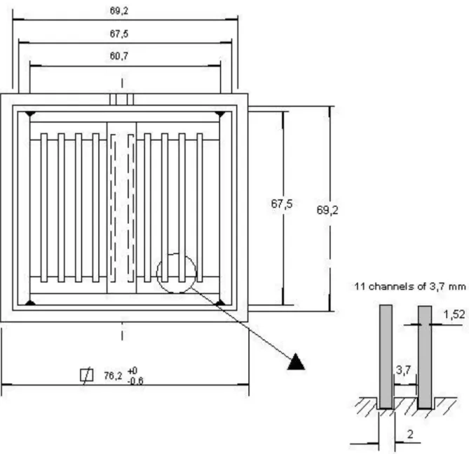
The main design parameters of CARR are shown in Table 1. The core is composed of 17 standard fuel assemblies and 4 follower fuel assemblies. Each standard fuel assembly is composed of 20 fuel plates separated by 21 coolant channels. All the standard fuel assemblies have the same geometry. All the fuel plates in the standard fuel assembly have the same shape and geometry. The channels in the assemblies vary in thicknesses and are symmetrical around the centre channel. The channels thickness variations are shown in Figure 3 (Xian et. al) below. As can be seen, there are 5 different channel thicknesses. In the code, the channels are numbered from left to right starting from 1 to 21 as shown in Figure 4. The geometry of fuel plates and coolant channels are summarized in Table 2
Table 5: Main design parameters of CARR.
Design parameters Input
Core diameter (m) 0.399
Core height (m) 0.85
Elevation of reactor pool water surface (m) 13.2 Core inlet temperature (oC) 35
Core inlet pressure 0.89
Core nuclear power (MW) 60
Core thermal power (MW) 56.4
Mass flow rate in primary loop (kg/s) 600 Number of standard fuel assembly 17 Number of follower fuel assembly 4
Type of fuel elements Plate
Figure 4: Channels thickness variation of the standard fuel assembly. Table 2: Fuel plate and coolant channels geometries.
Geometry parameter Input
Fuel plate
Fuel thickness[mm] 0.6
Fuel width [mm] 61.6
Fuel length [mm] 850
Cladding thickness [mm] 0.38
Fuel thermal conductivity [W/m.oC] 32
Cladding thermal conductivity 180
Coolant Channel
Channel width [mm] 71
Channel thickness [mm] Figure 4
Channel length [mm] 880
The power distribution in the fuel assemblies is represented by the radial power peaking factor distribution that is shown in Figure 5. The power generated in one assembly is assumed to be distributed equally between the different fuel plates in the assembly. The axial length of the active core is divided into 17 control volumes. Each control volume has its axial weighted power factor. The axial weighted power distribution used in the analysis is shown in Figure 6. 0 5 10 15 20 25 1.4 1.6 1.8 2 2.2 2.4 2.6 2.8 Channel number C h a n n e l th ic k n e s s [ m m ] Channel thickness
Figure 5: Radial power peaking factor distribution.
Figure 6: Axial weighted power distribution.
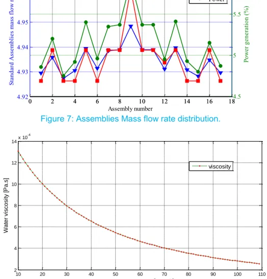
The results of thermal hydraulic analysis of CARR show a good agreement between the developed code and the results published by (Tian et al., 2005). The mass flow distribution in the standard fuel assemblies is shown in Figure 7. The results shows a good agreement with a maximum relative error of 0.3% which could be neglected. As can be seen from Figure 7, the assembly mass flow rates distribution follows the same trend in both results. The assembly with the highest power generation requires more mass flow rate in order to keep the same pressure drop. This phenomenon is studied in detail and the reason is found to be the effect of temperature on the density and viscosity of water. As it is already described the pressure drop is calculated using The Equation below
∆P𝑓𝑟𝑖𝑐𝑡𝑖𝑜𝑛 =1
2𝜌𝑉2
𝑓𝐿
𝐷ℎ
The friction factor used is calculated as
𝑓 = 0.316𝑅𝑒−0.25 0 1 2 3 4 5 6 7 8 9 10 11 12 13 14 15 16 17 18 19 20 21 22 0.7 0.8 0.9 1 1.1 1.2 1.3 1.4 Assembly number R a d ia l p o w e r p e a k in g f a c to r
Radial power peaking factor
0 1 2 3 4 5 6 7 8 9 10 11 12 13 14 15 16 17 18 0.2 0.4 0.6 0.8 1 1.2 1.4 1.6 1.8
Axial volume number
W e ig h te d p o w e r Weighted power (Fz)
Where Re is given by
𝑅𝑒 =𝜌𝑉𝐷
𝜇
And the velocity V is given by
𝑉 = 𝑚̇
𝜌𝐴
This gives the following equation for pressure drop
∆P𝑓𝑟𝑖𝑐𝑡𝑖𝑜𝑛 = ( 0.316 2 ) ( 𝐷ℎ−1.25𝐿 𝐴1.75 ) ( 𝜇0.25 𝜌 ) 𝑚̇
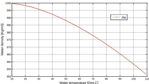
The first and second terms on the right hand side are independent of heat flux, and only the third term in parentheses is to be studied. The change in 𝜇 , 𝜌, and 𝜇0.25𝜌 with temperature is shown in Figures 7, 8, and 9 respectively. As can be seen from Figures 7 to 9, the effect of increasing the heat flux is to decrease the value of ( 𝜇0.25/𝜌 ), which in turn decreases the frictional pressure drop and so the total pressure drop.
Figure 7: Assemblies Mass flow rate distribution.
Figure 5-1: The change in water viscosity 𝝁 with temperature under a fixed pressure of 0.17 MPa. 0 2 4 6 8 10 12 14 16 18 4.92 4.93 4.94 4.95 4.96 4.97 Assembly number St an da rd A ss em bl ie s m as s f lo w ra te (% ) 0 2 4 6 8 10 12 14 16 184.5 5 5.5 6 Po w er g en er at io n (% ) CODE CARR Power 10 20 30 40 50 60 70 80 90 100 110 2 4 6 8 10 12 14x 10 -4
Water temperature [Deg.C]
W a te r vi sco si ty [P a .s] viscosity
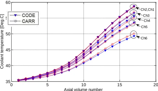
Figure 8: The change in water density 𝝆 with temperature under a fixed pressure of 0.17 MPa.
Figure 9: The change in 𝒙 =𝝁𝟎.𝟐𝟓
𝝆 with temperature under a fixed pressure of 0.17 MPa. The channels mass flow distribution is shown in Figure 10 below. As can be seen, the results show a good agreement. The maximum error in the channels flow rates is calculated to be 3.7%. 10 20 30 40 50 60 70 80 90 100 110 950 955 960 965 970 975 980 985 990 995 1000
Water temperature [Deg.C]
W a te r d e n si ty [K g /m 3 ] rho 10 20 30 40 50 60 70 80 90 100 110 1.3 1.4 1.5 1.6 1.7 1.8 1.9 2x 10 -4
Water temperature [Deg.C]
x
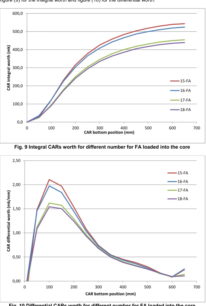
Figure 10: Channels mass flow distribution in the hot assembly (Assembly No.9). The axial coolant temperature profiles in Channels types numbered from 1 to 6 are shown in Figure 11 below. Figure 12 shows the zoom out view for channels 1 and 2. The coolant channels outlet temperatures for all the 21 channels (numbered 1 to 21 starting from left to right) of the hot assembly in CARR reactor are shown in Figure 13. The maximum difference is 0.7 oC.
Figure 11: Axial coolant temperature profile along the hot assembly for channels 1 to 6.
0 5 10 15 20 0.5 1 1.5 2 2.5 Channel number C h a n n e l m a s s f lo w r a te ( k g /s ) CODE CARR 0 5 10 15 20 35 40 45 50 55 60
Axial volume number
C o o la n t te m p e ra tu re [ D e g .C ] Ch5 Ch6 Ch4 Ch3 Ch2,Ch1
Figure 12: Zoom out of Figure III-11 around channels 1 and 2.
Figure 13: Channels coolant outlet temperatures in the hot assembly in CARR.
As can be seen from Figures 10 to 13, the mass flow rates and coolant temperature shows a very good agreement.
16.7 16.8 16.9 17 17.1 17.2 58.3 58.4 58.5 58.6 58.7 58.8 58.9 59
Axial volume number
C o o la n t te m p e ra tu re [ D e g .C ] Ch2 Ch1 0 5 10 15 20 45 50 55 60 65
Coolant channel number
C o o la n t T e m p e ra tu re [ D e g .C ] Tout-CODE Tout-CARR
Development of performance analysis code for research reactor fuel
G.Y. JEONG, D-S. SOHN
UNIST, 50 UNIST-gil, Eonyang-eup, Uljoo-gun, Ulsan 689-798 – Republic of Korea
Kyu Hong Lee, Jong Man Park
Korea Atomic Energy Research Institute, 989-111 Daedeokdaero, Yuseong, Daejeon 305-353,– Republic of Korea
ABSTRACT
Thermo-mechanical code dedicated to the modeling of U-Mo dispersion fuel plates is being under development in Korea to satisfy a demand for advanced performance analysis and safe assessment of the plates. The major physical phenomena during irradiation are considered in the code such that interaction layer formation by fuel-matrix interdiffusion, fission induced swelling of fuel particle, mass relocation by fission induced stress, and pore formation at the interface between the reaction product and Al matrix.
The framework of performance analysis code for U-Mo dispersion fuel has been established with newly updated models.
1. INTRODUCTION
The need to develop an advanced performance and safety analysis code for research reactor fuel grows in Korea. A performance analysis modeling applicable to research reactor fuel is being developed with available models describing fuel performance phenomena observed from in-pile tests. We established the calculation algorithm and scheme to best predict fuel performance using radio-thermo-mechanically coupled system to consider fuel swelling, interaction layer growth, pore formation in the fuel meat, and creep fuel deformation and mass relocation.
In this paper, we present a general structure of the performance analysis code for typical research reactor fuel and advanced features such as a model to predict fuel failure induced by combination of breakaway swelling and pore growth in the fuel meat.
2. CODE FRAMEWORK
Accurate prediction of fuel temperature and states of stresses induced by fission is essential for research reactor fuel performance code. It is necessary to employ proper and sufficient models that are applicable evaluate in-pile behaviors such as a dimensional change, stress-strain variation, and material degradation by fission and neutron irradiation.
Drastic microstructure changes in the dispersion fuel meat have been observed and investigated including interaction layer (IL) formation by fuel-Al matrix interdiffusion, fuel-Al
matrix consumption, and large pore formation, particularly at the interface of IL and Al matrix. It is necessary to take into consideration of the coupling between thermal and mechanical response to predict those microstructure variation of the meat.
In this section, a general fuel performance model implemented in the code such as temperature calculation, stress-strain analysis, fission induced swelling are described.
2.1. PERFORMANCE MODEL
The coupling among thermal, mechanical, and irradiation-related performance issues is critical to fuel performance modeling. Typical operation temperature for U-Mo/Al dispersion fuel meat for plate type is below 200 oC, but it is dependent on fuel meat thermal conductivity which is
influenced by fuel meat morphology and material composition. Particularly, fuel meat thermal conductivity degradation is mostly influenced by Al matrix depletion by IL growth since it is believed that IL has poor thermal conductivity.
The variation of fuel meat morphology is induced by three major phenomena : fuel swelling, IL formation, and pore formation. Details of models implemented in the code are described in the following subsection.
2.1.1. FUEL SWELLING
U-Mo fuel swelling is dependent on Mo content. An empirical correlation for U-10Mo fuel swelling was documented by Kim [1]. U-10 wt% Mo fuel swelling is given as a function of fission density (FD) as follows : 21 3 0 2 21 3 0 ( ) 5.0 3 10 fission/cm ( ) 15 6.3( 3) 0.33( 3) 3 10 fission/cm f d d f d d d V f f V V f f f V (1) where
f
d is in 10 21 fission/cm3.The correlation for U-7 wt% Mo fuel swelling is also expressed as a function of FD as follows [2]:
21 3 0 2 21 3 0 ( ) 5.0 2 10 fission/cm ( ) 10 6.7( 2) 0.58( 2) 2 10 fission/cm f d d f d d d V f f V V f f f V (2) where
f
d is in 10 21 fission/cm3.Compared to the U-10Mo fuel, the fuel swelling model for U-7Mo gives higher swelling rate since grain subdivision is assumed to occur at lower FD due to lower Mo content.
2.1.2. INTERACTION LAYER
IL growth is believed to cause an increase in meat volume. A time-dependent volume fraction of IL in meat needs to be modeled to evaluate volume expansion by IL growth.
IL growth models by using in-pile test data have been reported [3],[4]. The available IL growth model for in-pile tests is given as a modified Arrhenius equation, in which the fission rate is multiplied to account for fission-enhanced diffusion:
2 8 0 2.6 10 exp( 3850) Y f t T (3)
where
Y
0 is IL thickness for pure Al matrix in µm, f the fission rate in fission/cm3-sec, T the temperature in K, and t the irradiation time in second.The addition of Si in the Al matrix reduced IL thickness growth. It is also known that IL growth is dependent on the Mo content in the fuel. Additional factors to consider Si and Mo effects on IL growth are multiplied to Eq.(3) as follows:
2 2
0 Si Mo
Y Y f f (4)
where Y is IL thickness for Si-added Al matrix in µm
f
Si is the reduction factor by Si additioninto the matrix and
f
Mo the Mo content factor on IL growth. Detailed explanation on theseadditional factors can be found in [4]. 2.1.3. PORE FORMATION
Pores are formed in dispersion fuel; 1) pores within fuel particles, 2) pores in interaction layers (ILs), 3) pores at the interfaces (Fuel-IL, IL-Al). The pores contain fission gases. Pores in the ILs, specifically at IL-Al interfaces, tend to be larger than those in the fuel particles. Pore formation degrades fuel performance and integrity and has a potential to cause fuel failure.
Mechanism of pore formation, particularly at the interface between IL and Al matrix has been studied by different authors Error! Reference source not found.,[7]. It is assumed that the large pore formation is initiated with as-fabricated pores in the meat and fission gases released to those pores is a driving force of pore growth.
The advanced code is desired to have capability to predict fuel failure caused by pore formation and growth. To fulfil this, pore formation mechanism needs to be investigated further.
2.1.4. MASS RELOCATION
The mass transport of the meat in the dispersion fuel plate observed at the meat end region where fission density is highest along the width of the plates, has been studied [5],[6]. It is believed that the stresses caused by fission induced fuel swelling, and chemical volume expansion by interaction layer growth were mitigated by the creep deformation of a continuous phase which surrounds fuel particles.
The following equation was employed for the creep rate of the U-Mo fuel particles as:
c
A
cf
(5)where
c is the equivalent creep rate in s-1,
c
A
the creep rate constant in cm3/MPa, and f the fission rate in fission/cm3-sec.Recently updated modelling for mechanical deformation of fuel particles and meat swelling caused by fission-induced creep is considered in the developed code.
2.2. CODE STRUCTURE
Finite element analysis will be employed to calculate the temperature distribution in the fuel meat and cladding region. A fuel plate sectioned in length direction is shown in Fig. 1. Typical plate length is longer than any other dimension, so that it is assumed that heat conduction in the length direction is negligible. It also allows strain out of plane to be constant or zero, which is plane strain condition.
Fig. 1 A schematic of dispersion fuel plate and cross section at axial mid-plane.
The temperature distribution throughout the fuel meat and cladding in 3-dimension is calculated at each node. The models used in the temperature calculations assume a transversally symmetrical fuel plate surrounded by coolant.
User supplied conditions such as coolant information including coolant inlet temperature, coolant flow velocity, and coolant mass will be used to determine boundary conditions. User supplied fission rate will be used to calculate temperature distribution from the coolant to the meat centerline. A film temperature rise from the bulk coolant to cladding surface is calculated by finding film heat transfer coefficient for a given coolant and geometry. The temperature at the interface between clad and meat is calculated by using Fourier’s law. The temperature rise to the meat centerline is determined by solving heat conduction equation for fuel particle, Al matrix, and IL with heterogeneously.
meat , ( (T) ) ''' '' '' ( ) fuel clad clad c c o coolant k T q q k T q h T T (6)
Where q’’’ is the power density in the meat, k the thermal conductivities, q’’meat the total heat flux
from the meat, q’’clad the heat flux from the cladding surface, Tc,o the cladding outer surface, and
Tcoolant the bulk coolant temperature.
With assumption on strain condition as mentioned, meat and cladding deformation calculation will be performed after obtaining temperature distribution. An accurate calculation of stresses in the meat and the cladding is needed to accurately calculate the strain and evaluate a potential of large pore formation and fuel failure.
Strain caused by irradiation can be obtained by solving the mechanical equilibrium equation as follows:
(T) ''' 0f
(7)where
is the density, f’’’ is volumetric forces induced by fission, and
the stress tensor. Fig. 2 shows the overall structure of the new code system. Each performance model will be classified in several modules. Mechanical response prediction for each plate component will be performed with prescribed condition from previous thermal analysis.Fig. 2 Overall structure of research reactor fuel performance code.
3. CONCLUSION
Thermo-mechanical code dedicated to the modeling of U-Mo dispersion fuel plates is being under development in Korea to satisfy a demand for advanced performance analysis and safe assessment of the plates. The major physical phenomena during irradiation are considered in the code such that interaction layer formation by fuel-matrix interdiffusion, fission induced swelling of fuel particle, mass relocation by fission induced stress, and pore formation at the interface between the reaction product and Al matrix.
The framework of performance analysis code for U-Mo dispersion fuel has been established with newly updated models with studies on advanced fuel performance modeling.
ACKNOWLEDGMENTS
We would like to acknowledge helpful discussion and kind consultation by Yeon Soo Kim. UNIST was supported by the National Research Foundation of Korea (NRF) grant funded by the Korean government (Ministry of Education, Science and Technology) (No. 2011-0031771), and in part by National Nuclear R&D Program sponsored by Ministry of Science, ICT and Future Planning. (NRF-2013M2A8A1041241) for the KAERI contribution.
REFERENCES
[1]
Yeon Soo Kim, G.L. Hofman, J. Nucl. Mater., 419 (2011) 291.[2]
Yeon Soo Kim, G.Y. Jeong, G.L. Hofman, J. Nucl. Mater., submitted (2015).[3]
D.M. Wachs, D.E. Burkes, S.L. Hayes, W. Skerjanc, G.L.Hofman, Yeon Soo Kim, H.J. Ryu, Proc. Int. Meeting on Reduced Enrichment for Research and Test Reactors (RERTR), Cape Town, South Africa, Oct.29 - Nov. 2, 2006.[4]
Yeon Soo Kim, G.L. Hofman, H.J. Ryu, J.M. Park, A.B. Robinson, D.M. Wachs, Nucl. Eng. Technol., 45 (2013) 827.[5]
Yeon Soo Kim, G.L. Hofman, J.S. Cheon, J. Nucl. Mater., 436 (2013) 14.[6]
G.Y. Jeong, Yeon Soo Kim, D-S. Sohn, J. Nucl. Mater., submitted (2015).[7]
A. M. Tentner, A. Bergeron, Y. S. Kim, G. L. Hofman, J. G. Stevens, S. Van den Berghe, V. Kuzminov, Proc. Int. Meeting on Reduced Enrichment for Research and Test Reactors (RERTR), Vienna, Austria, Oct.12 - 15, 2014.[8]
A. Leenaers, S. Van den Berghe, E. Koonen, V. Kuzminov, C. Detavernier, J. Nucl. Mater. 458 (2015) 380.EVALUATION OF PERFORMED EXPERIMENTS ON FAST
MULTIPLYING SYSTEMS WITH HEU FUEL FOR RECEIVING
BENCHMARK DATA ON CRITICALITY
S.N.SIKORIN, S.G.MANDZIK, S.A. POLAZAU, A.V. KUZMIN,
Y.V.DAMARAD, I.S. SOLTAN
The Joint Institute for Power and Nuclear Research – Sosny, 99 Academic Krasin Street, 220109 Minsk - Republic of Belarus
ABSTRACT
Benchmark criticality experiments of fast heterogeneous configurations with HEU fuel were performed using “Giacint” critical facility of the Joint Institute for Power and Nuclear Research – Sosny of the National Academy of Sciences of Belarus. The critical assemblies’ cores have consisted from fuel assemblies of without a jacket. Fuel assemblies contain 19 fuel rods of two types. The first one is metallic U (90% U-235); the second one is UO2 (36%
U-235). The active area length is 500 mm. The clad material is stainless steel. Three types of fuel assemblies with different content fuel rods were used. Side radial reflector: an inner layer – Be, an outer layer – stainless steel. The top and bottom axial reflectors – stainless steel. The analysis of the experimental results obtained from these benchmark experiments by developing detailed calculation models and performing simulations for the different experiments is presented. The sensitivity of the obtained results for the material specifications and the modeling details were examined. The analyses used the MCNP and MCU computer programs. This paper presents and compares the analytical model details, the obtained experimental and analytical results.
1. Introduction
This paper presents the experimental and analytical parameters of criticality of the uranium-containing fast neutron multiplication systems with a core based on fuel assemblies with 36% and 90% U-235 fuel rods. The experiments were performed using the “Giacint” critical facility of the Joint Institute for Power and Nuclear Research – Sosny (JIPNR-Sosny) of the National Academy of Sciences of Belarus [1]. The experimental results were analyzed in order to estimate whether they can be used as benchmark criticality data
.
2. Fast critical assemblies
The fast critical assemblies represent a lattice (35.7 mm pitch) of fuel assemblies with fuel rods based on metal uranium and uranium dioxide, 90% and 36% enrichment by U-235, respectively, with a beryllium-steel reflector (Fig 1). The critical assemblies included the core, the side reflector, the top and bottom axial reflectors and the control and protection system (CPS) rods. The cores of critical assemblies, comprising fuel assemblies, are surrounded by several rows of beryllium and steel reflector units. These elements of the critical assemblies are placed on the stainless-steel support grid. The neutron detectors are attached on special poles around the critical assemblies.
The support grid of the critical assemblies is placed on the frame and represents a stainless-steel cylinder, 950 mm in diameter and 40 mm in thickness. The support grid has 18.2 mm diameter holes drilled in the hexagonal lattice with the 35.7 pitch; the holes receive the shanks of the fuel assemblies and the side reflector units.
The fuel assemblies (Fig 2) represent assemblies without a casing and comprises 19 fuel rods. There are three types the fuel assemblies: type 1 — 16 fuel rods type 2 and 3 fuel rods type 1; type 2 — 19 fuel rods type 2; type 3 — 19 fuel rods type 1 (Fig 3). The fuel rods are arranged around the hexagonal grid with the 8 mm pitch and are fixed by means of the end parts. The fuel assemblies have dimensions for the 34.8 mm wrench, with the total length 1047 mm (the active part in 500 mm long, the top shank of the fuel rod is 60 mm, the top shank of the fuel rod is 60 mm, the top end parts of the assembly are 216 mm, and the bottom end parts of the cassette are 211 mm). All top and bottom end parts of the fuel assemblies are made from stainless steel.
Fig 1. The fast critical assembly
Fig 2. Fuel assembly:
A A A-A 35 C-C C C B view B 206 166 10 10 1 2 3 4 3 5 6
The type 1 fuel rod (Fig 4) comprises a fuel core, a clad and end parts. The fuel rod cladding is from stainless steel with the outer diameter 7 mm and the wall 0.2 mm thick. The fuel core comprises tablets, 6.4 mm in diameter and 5 mm in height, made from metal uranium 18.9 g/cm3. The U-235 enrichment is 90%. The total core height is 500 mm. The U-235 weight in the fuel rod is 259.8 g. The top shank of the fuel rod is made from stainless steel with the 60 mm length and 6.6 mm diameter. The bottom end part of the fuel rod comprises the bottom shank 10 mm long and 6.6 mm in diameter and the bushing 50 mm long with the 6.6 mm diameter. The fuel rod is sealed, with the total length 620 mm.
The type 2 fuel rod (Fig 4) has the same structure as type 1 fuel rod, but with a different fuel core, comprising tablets with the 6.4 mm diameter and the 4-7 mm height, made from uranium dioxide 9.8 g/cm3. The enrichment by U-235 is 36%. The total fuel core height is 500 mm. The
90% U-235 weight in the fuel rods is 49.1 g.
The side reflector of the critical assemblies is several rows of the beryllium and stainless steel reflector units. The bottom axial reflector of the critical assemblies comprises bottom plugs of the fuel rods, bottom end parts of the fuel assemblies and the support plate. The top axial reflector of the critical assembly comprises top ends parts of the fuel rods and top end parts of the fuel assemblies.
Fig 3. Layout of fuel rods in the fuel assemblies — fuel rod type 2 — fuel rod type 1
fuel assembly type 1 fuel assembly type 2 fuel assembly type 3
Fig 4. Fuel rod type 1 (type 2):
1 – upper end part; 2 – cladding; 3 – fuel core; 4, 5 – lower end part А-А view 7 M3 7 500 620 60 7 6,6 6,4 A A M3 50 1 2 3 4 5
The beryllium reflector unit (Fig 5) represents a hexagonal prism beryllium prism for the 34.8 mm wrench, 972 mm long. The bottom part of the unit bears a stainless steel shank, representing a seating surface when loaded into the critical assembly. The top part of the unit bears a stainless steel head for the 34.8 mm wrench, 40 mm long. The total length of the beryllium reflector unit is 1047 mm.
The steel reflector unit (Fig 6) is made from stainless steel, representing a hexagonal prism for the 34.8 mm wrench, 1047 mm long. The bottom part of the unit bears a shank, representing a seating surface when the critical assembly is installed on the support plate.
The control and protection system of this critical assembly included three rods for emergency protection (EP), three rods for manual regulation (MR) and three rods of compensating reactivity (CR).
3. Neutron physical parameters of the critical assemblies
Figures 7 – 10 represent loading charts of the fast critical assemblies. The core and reflector compositions of the fast critical assemblies are presented in Tab 1.
Fig 6. Steel reflector unit
А А 1 2 3 4 2 27,8 25
Fig 5. Beryllium reflector unit:
Fig 7. Loading chart of the critical assembly type 1 — fuel assembly type 2
— fuel assembly type 1 — beryllium reflector unit — steel reflector unit
— fuel assembly type 2 — fuel assembly type 1 — beryllium reflector unit — steel reflector unit
Fig 8. Loading chart of the critical assembly type 2
— beryllium reflector unit — steel reflector unit — fuel assembly type 3
Fig 9. Loading chart of the critical assembly type 3
— beryllium reflector unit — steel reflector unit — fuel assembly type 3
The critical
assembly
The fuel assembly, pcs
Beryllium
reflector
unit,
pcs
Steel
reflector
unit,
pcs
type 1
type 2
type 3
Type 1
19
24
—
189
99
Type 2
19
24
—
174
114
Type 3
—
—
7
72
78
Type 4
—
—
7
69
78
Tab 1: The core and reflector compositions of the fast critical assemblies
The neutron physical characteristics of the critical assemblies are measured by the experimental unit “Reactivity Meter”, using the inverted solution of reactor kinetic equation [2, 3]. In order to exclude spatial effects of reactivity, the measurements were made using three ionization chambers, arranged at every 120 behind the side reflector of the critical assembly. For estimating the results of the critical experiments we calculated the effective neutron multiplication coefficient Кeff of the fast critical assemblies. The calculations were made by the
Monte Carlo method using the MCNP-4С [4] and MCU-PD [5] computation codes. The experimental data and the calculation results are presented in Tab. 2.
The critical
assembly
Reactivity
measurement
result *,
effК
effcalculation result
effc
result
alculation
MCNP-4C MCU-PD
MCU-PD
Type 1
0,43 ± 0,02
±0,00012
1,00447
±0,00037
1,00349
±0,000003
0,007454
Type 2
-0,09 ± 0,01
±0,00017
1,00176
±0,00043
1,00059
±0,000003
0,007467
Type 3
0,60 ± 0,02
±0,00022
1,00310
±0,00050
1,00130
±0,000003
0,007227
Type 4
0,03 ± 0,01
±0,00022
0,99860
±0,00036
0,99764
±0,000003
0,007227
* – total error of experimental results for the given confidence probability 0,68.Tab 2: The experimental data and the calculation results of the fast critical assemblies
4. Conclusions
Analysis of the experimental data (including data on the composition and sizes of the critical assembly components) and of the calculated Кeff allows a conclusion that the results of criticality
5. References
[1] Sikorin S., Hryharovich T. Research Nuclear Installations in Republic of Belarus / Enhancing Use and Safety of Research Reactors through Networking, Coalitions and Shared Best Practices, IAEA, Vienna, Austria, 10-14 February 2014. — CD.
[2] S.A. Polazau, S.N. Sikorin, "Digital reactimeter on the basis of the microcomputer and apparatus «CAMAC»", Proceedings of the Academy of Sciences of Belarus, Power engineering physical series, № 4, pp. 87-92, 1987.
[3] G.I. Buznitsky, A.I. Golovach, F.A. Grinevich, V.V. Luk’yanets, N.M. Sidoruk, S.N. Sikorin "An analogous meter for measuring nuclear reactor reactivity", Proceedings of the Academy of Sciences of Belarus, Power engineering physical series, № 1, pp.22-27, 1992.
[4] ”MCNP – A General Monte Carlo N-Particle Transport Code, Version 4C,” Ed. J. F. Briesmeister, Report LNL, LA-13709-M, 2000.
[5] Application Description and User’s Manual for MCU-PD program: report №36-10/30-11 / NRC "KURCHATOV INSTITUTE" . — Moscow, 2011. — 569 p.
JRTR INITIAL CRITICALITY CALCULATIONS AND NUCLEAR
COMMISSIONING TESTS
MUSTAFA K. JARADAT, S. ALKHAFAJI, K. ABU SALEEM
Research Reactor Project, Jordan Atomic Energy CommissionP. O. Box 70, Amman 11934, Jordan
CHANG JE PARK
Sejong University, 209 Neungdong-ro, Gwangjin-gu, Seoul, Republic of Korea And Reactor Core Design Division, Korea Atomic Energy Research Institute
1045 Daeduk-Daero, Yuseong-Gu, Daejeon, 305-353, Korea
ABSTRACT
The Jordan Research and Training Reactor (JRTR) is a multi-purpose open-tank in pool type reactor under construction with nominal power of 5 MW. The core consists of 18 fuel assemblies with low enriched uranium (LEU) of 235U enrichment of 19.75%. During the commissioning of JRTR
many tests will be performed. In this work the initial criticality and fuel loading pattern are simulated using Monte Carlo code McCARD. One fuel loading scheme had been chosen based on lowest amount of fuel loaded into the core and the smallest number of fuel assemblies loaded. Also the control rods worth calculation using swap method have been modeled for a fully loaded core. These calculations should be compared with measured results during commissioning tests of JRTR.
1. Introduction
Jordan Research and Training Reactor (JRTR) is a multi-purpose open-tank-in-pool type reactor under construction with nominal power of 5 MW. The JRTR core consists of standard and special MTR fuel assemblies. A standard fuel assembly is a plate-type, a total of 21 fuel plates with aluminum-clad constitute. The fuel for the core is low enriched uranium (LEU) with a 235U enrichment of 19.75 weight %. Each fuel plate is composed of a fuel meat with
surrounding aluminum cladding. The fuel meat is made of fine and homogeneous dispersion of U3Si2 particles in a continuous aluminum matrix with a uranium density of 4.8 g U/cm3.
The JRTR core configuration contains 18 fuel assemblies with four control absorber rods and two second shutdown rods. The control absorber rod is a square tube with the neutron absorbing material made of Hafnium, while for the second shutdown rods B4C powder is used as the neutron absorbing material. The core has a central flux trap, four beam ports, and several irradiation holes. The reactor is light water moderated and cooled and reflected with beryllium and heavy water. [1]
2. Initial Core Description
The initial core configuration is determined based on the following strategies: the initial core should be similar to the equilibrium core; the excess reactivity should be enough for a good
fuel economy, the reactor controllability should be maintained, the power peaking factor should be as low as possible, the transition from the initial core to the equilibrium core should be easy, and the number of fuel types should be minimized.
The initial core is configured using fuel assemblies of different densities. Fuel assemblies are fully loaded at the appropriate locations in view of the controllability of reactivity worth in the core and the safety margin. Figures 1 and 2 depict the core configuration and the initial fuel loading with 4 different densities of 4.176, 4.784, 5.878, and 6.543 g/cm3. Table 1 lists the
major parameters of the fuel and core. [1]
Fig.1 Plan View of the JRTR Core
Fig.2 Initial Fuel Loading of JRTR F01 4.0 5.878 F02 4.8 6.543 F03 4.0 5.878 F04 2.6 4.784 F05 2.6 4.784 F06 1.9 4.176 F07 2.6 4.784 F08 2.6 4.784 F09 1.9 4.176 F10 1.9 4.176 F11 2.6 4.784 F12 2.6 4.784 F13 1.9 4.176 F14 2.6 4.784 F15 2.6 4.784 ID gU/cc Density (g/cm3) F16 4.0 5.878 F17 4.8 6.543 F18 4.0 5.878
Table (1) Major Parameters of the Core, Fuel Assembly and Fuel Plate
Reactor Core Data
Number of fuel assembly sites
Number of irradiation sites in the Be reflector Number of control absorber rods
Number of second shutdown rods Number of beam tubes
Reactor power 18 12 4 (Hf) 2 (enriched B4C) 4 5 MW Fuel Meat, Plate and Assembly Data Fuel meat thickness
Cladding thickness Fuel plate thickness Fuel plate width Fuel plate length
Coolant channel thickness
Number of fuel plate/Fuel assembly Fuel assembly width
Fuel assembly height
0.51 mm 0.38 mm 1.27 mm 70.7 mm 680 mm 2.35 mm 21 76.2 mm 1015 mm
Material Property Data
Fuel meat
Uranium density in fuel meat Fuel meat density
Cladding
Cladding density
U3Si2–Al
4.8 gU/cm3
6.543 g/cm3
AG3NE (aluminum alloy) 2.7 g/cm3
3. JRTR Commissioning Tests
The commissioning of JRTR is required to demonstrate that the requirements and intents of the design as stated in the safety analysis report can be met. The commissioning activities should include adequate testing and inspection of structures, systems and components based on the importance of reactor safety. A graded approach for testing should be properly established in advance from the planning stage. The tests have to be arranged in functional groups and in a logical sequence and to be conducted with written procedures. The commissioning tests and stages are divided into few different sequences as follows;
a) Stage A for pre-fuel loading tests.
b) Stage B for fuel loading tests, initial criticality tests and low power tests. c) Stage C for power ascension and power tests.[2]
In stage B neutronics tests must be carried out following the test procedures, so simulation results of these tests must be provided in advance. Some of these tests are:
a) Fuel loading and approach to the first criticality of JRTR b) Configuration of operation core
c) Tests and experiments at zero-power d) Test and experiments at each power level.
In this work the initial criticality of the JRTR core and control absorber rods worth were investigated using McCARD code. McCARD is a Monte Carlo Code for Advanced Reactor Design & Analysis. It was developed in the Department of Nuclear Engineering of Seoul National University since 1998. McCARD is a Monte Carlo (MC) neutron-photon transport simulation code designed exclusively for neutronics analyses of various nuclear reactors and fuel systems. McCARD estimates of neutronic design parameters of a nuclear reactor or fuel
system such as effective multiplication factor (keff), neutron flux and current fission power,
etc. by using continuous-energy cross section libraries and detailed geometrical data of the system. [3]
4. Results of JRTR Fuel Loading and Initial Criticality:
Fuel loading, removal of the absorber or addition of the moderator during the approach to criticality necessitates calculations or estimates to predict changes in core reactivity, and periodic measurements of subcritical multiplication to determine subsequent safe increments of reactivity.
For fuel loading to reach first criticality of the core the fuel assemblies are loaded into the core one by one until the core approach criticality. After adding each fuel assembly the multiplication factor must be checked before adding the next one. When the core reaches critical state the control rods should be inserted into the core before adding fuel assembly until the core is fully loaded and the control rods are at the critical position. So the fuel loading pattern should be defined in advance before starting real fuel loading into the core to avoid approaching any super critical state.
Criticality calculations using McCARD were performed to determine fuel loading scheme to approach to criticality. For fuel loading 20 core configurations were simulated for the first criticality but four configurations were suggested for fuel loading of JRTR core as shown in figure (3) because they can make the reactor critical without control rods.